
Related Manuals for Tynetec Reach


Summary of Contents for Tynetec Reach
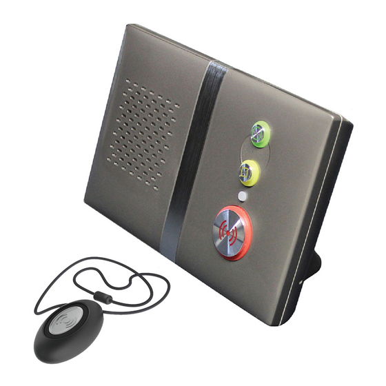
- Page 1 Reach At‐Home Alarm Unit Touch Personal Pendant USER & INSTALLATION GUIDE www.tynetec.co.uk ...
-
Page 2: Table Of Contents
SECTION 1 – USER INSTRUCTIONS Section Topic Page 1.1 Important Information 3 1.2 Unpacking the Reach At‐Home Alarm 3 1.3 The Touch Personal Pendant 4 1.4 Connecting the Reach At‐Home Alarm 5 1.5 Reach and Extension Telephones 6 1.6 Reach and Broadband 6 1.7 Switching the Reach At‐Home Alarm on 7 1.8 Switching the Reach At‐Home Alarm off 7 1.9 Making an Emergency Call 8 1.10 Accidental calls 9 1.11 ... -
Page 3: Important Information
ALSO AVAILABLE IN WHITE Touch Pendant Reach At‐Home Alarm Wearing Kit Connector Cover ... -
Page 4: The Touch Personal Pendant
Making an Emergency Call… Simply press the Touch pendant button once. The button will FLASH RED (( )) for several seconds to confirm a call is being made. The Reach will announce “Pendant alarm – Please wait, dialling for assistance” The Touch pendant battery should last for about 3‐5 years depending on use. The battery condition is checked every day, if the voltage falls and stays below a preset level for 7 consecutive days a “low battery” call will automatically be sent to the Control Centre. Pendants must be returned to Tynetec for battery replacement. ‐ 4 ‐ ... -
Page 5: Connecting The Reach At-Home Alarm
1.4 CONNECTING THE REACH AT‐HOME ALARM The Reach At‐Home alarm unit should only be installed and programmed by trained personnel. Basic Connections… IMPORTANT Reach This aerial wire receives signals TELEPHONE AT‐HOME ALARM UNIT from radio devices and must not be cut‐down or coiled‐up BT WALL Manufactured in the UK by tynetec SOCKET REN 1.0 Receiver Frequency 169.48125MHz Complies with: ECC/DEC/(05)02 ETSI EN 300 220-2 Class 1 No user serviceable parts inside case. -
Page 6: Reach And Extension Telephones
WITH SOCKET DOUBLE ADAPTER INCOMING TELEPHONE LINE 1.6 REACH AND BROADBAND Broadband Service Providers will supply a filter module to plug into the telephone line to allow connection of a computer and a normal telephone. Only one filter module is required to connect the computer, telephone and Reach when configured as shown below; USERS TELEPHONE REACH AT-HOME ALARM UNIT BROADBAND MASTER FILTER TELEPHONE MODULE SOCKET INCOMING TELEPHONE LINE COMPUTER The Reach and the computer are connected to the filter module. The users telephone is plugged into the Reach TEL socket. If extension telephones are fitted they should be connected as shown in section 1.5 above. If you experience connection difficulties or noise on the Reach audio then a poor quality filter may be the cause. Approved filter modules are available from Tynetec – order P/No. W00409. ‐ 6 ‐ ... -
Page 7: Switching The Reach At-Home Alarm On
“Please check your DO NOT UNPLUG SWITCH OFF mains supply” 2. Press and HOLD the GREEN button until the unit “beeps” once… “Beep” 3. RELEASE the GREEN button and the unit will announce… “Powering down” 4. The Reach is now switched off. The telephone plugged into the Reach will still operate when the unit is switched off. ‐ 7 ‐ ... -
Page 8: Making An Emergency Call
before the unit starts to dial. 3. The call will be answered by the control centre and an operator will speak… ”You’re through to Care Line, how can I help you?” 4. A two way conversation can be held with the resident. 5. The operator will cancel the call and the front light will return to STEADY GREEN. If the operator cannot hear the caller they will still know where the call is coming from. The Touch pendant does NOT pick up voice, the microphone is in the Reach unit and is very sensitive but it will not work if the caller is outside their home. The control centre can increase the volume if the caller has difficulty hearing. ‐ 8 ‐ ... -
Page 9: Accidental Calls
If an emergency call is made by accident it can be cancelled by pressing the GREEN button once. The unit will announce “Alarm cancelled” and the front light will return to STEADY GREEN. “Alarm cancelled” Please note once the Reach starts to dial the call cannot be cancelled. Advise the user not to worry if they don’t manage to cancel an accidental call – when the control centre answers they just need to say the call was made accidently. The staff will be pleased that they have talked and they will cancel the call in the normal way. 1.11 ANSWERING AN INCOMING TELEPHONE CALL The Reach can also be used to answer a normal incoming telephone call… ... -
Page 10: Using The Personal Recipient Mode
1.12 USING THE PERSONAL RECIPIENT MODE The Reach can be set to dial up to 4 different personal recipients (e.g. relatives or friends). The personal recipient telephone numbers (PR1‐PR4) must be programmed – see section 2.3.5 A personal recipient message must be recorded – see section 2.3.10 To answer a personal recipient call… When the telephone rings, press the Green line key “Beep… Beep…” (or pick‐up) and answer in the normal way. RING If the call is from the Reach unit you will hear a single “Beep” every 2 seconds. ... -
Page 11: Activity Monitoring And The Away Mode
The unit is now in Away Mode and their activity monitoring is turned off. When the resident returns home they must remember to turn their activity monitoring back on... Press the YELLOW button and the unit will announce… “Home” The front light will go STEADY GREEN The unit is now back in Normal Mode and their activity monitoring will be working again. Activity Monitoring must be enabled during the programming of the Reach unit. See section 2.3.6 for details. ‐ 11 ‐ ... -
Page 12: Using The Intruder Mode
and the unit will announce… “Intruder mode disabled” Failure to disable the intruder mode will send a “silent” alarm call to the control centre. Intruder Mode must be enabled during the programming of the Reach unit. See section 2.3.11 for details. ‐ 12 ‐ ... -
Page 13: Mains Power Failure Alert
1.15 MAINS POWER FAILURE ALERT The Reach will make the resident aware if their mains electricity is off or if the power lead has been accidently unplugged... The front light will FLASH AMBER and the unit will announce… “Please check your mains supply” This message will repeat 3 times every 4 hours until the mains power is restored. ... -
Page 14: Battery Failure Alert
1.17 BATTERY FAILURE ALERT The Reach will make the resident aware if its battery is beginning to lose charge… The front light will FLASH AMBER and the unit will announce… “Back‐up battery low” This message will repeat 3 times every 4 hours until the battery is replaced. To silence the message and prevent it repeating again, press the GREEN button. ... -
Page 15: Quick Start Guide
2.1 QUICK START GUIDE This Quick Start Guide takes you through the most basic set‐up possible when installing a Reach. This assumes the Reach will be dialling a control centre (not a personal recipient) and all other settings are factory default. Connecting the Reach… 1. Unplug the users Telephone from the BT wall socket and plug it into the Reach TEL socket. 2. Connect the Telecom Lead between the BT wall socket and the Reach C/O socket. 3. Connect the Power Lead between a mains socket and the Reach SUPPLY socket. Power‐up and Enter Program Mode… 1. Switch the mains supply on ‐ the front light on the Reach will flash RED/AMBER/GREEN. 2. Enter 1 6 7 0 using the keypad on the rear, the unit will announce “Program Mode – Ready” and the front light will FLASH FAST GREEN. Programming the Unit ID Number… 1. Enter # 0 2 4 and the unit will announce “Unit ID”. 2. Enter the unit ID number followed by the # key. 3. The unit will announce “Ready”. Programming the Telephone Number… 1. Enter # 0 2 6 and the unit will announce “Telephone Number 1”. 2. Enter the control centre telephone number followed by the # key. 3. The unit will announce “Ready”. Note: up to 4 different telephone numbers can be entered using codes #027, #028 & #029. ... -
Page 16: Programming Mode
2.2 PROGRAMMING MODE The keypad on the rear of the Reach is used to program the unit ID, control centre telephone number, protocol type, etc. It may be necessary to remove the stand to access the keypad. Enter 1 6 7 0 using the keypad on the rear… The front light will FLASH FAST GREEN and the unit will announce… ... -
Page 17: Programming The Telephone Number
2.2.2 PROGRAMMING THE TELEPHONE NUMBER The telephone number will be issued by the control centre (max 12 digits). Press # 0 2 6 and the unit will announce... “Telephone number 1” Enter the telephone number then press # If the number was entered correctly you will hear the “Ready” prompt. Press the 1 key to confirm what you entered… ... -
Page 18: Programming Parameters List
2.3 PROGRAMMING PARAMETERS LIST Enter Default See Menu Group Parameter Enter the following data… Parameter No. Setting Section Load Defaults #000 Load Defaults Load System Defaults #001 Enter the required default parameter 2.3.1 followed by # and Parameter Check Load Radio Defaults #002 Check Parameters #003 GSM Mode #004 0# = Disable or 1# = Enable Disabled Siren Volume #005 Level 3 Enter 0 to 5 followed by # Audio Volume #006 0# = off, 1# = min volume to Level 3 5# = max volume ... -
Page 19: Load Defaults & Parameter Check
2.3.1 LOAD DEFAULTS & PARAMETER CHECK Load Defaults – clears all programming, the personal recipient message and all radio devices from the Reach memory. Enter #000; the unit will announce “Load Defaults” then press #. Load System Defaults – clears all programming from the Reach memory. Enter #001; the unit will announce “Load System Defaults” then press #. Load Radio Defaults – clears all radio devices from the Reach memory. Enter #002; the unit will announce “Load Radio Defaults” then press #. Check Parameters – confirms the unit ID, telephone numbers, protocol type, the pendant ID (plus any other radio devices learned into the unit) and the software revision. Enter #003 and the unit will announce the above settings. 2.3.2 AUDIO SETTINGS GSM Mode – this mode should only be enabled if the Reach is being connected via the Mobile network using a GSM unit rather than a conventional PSTN land line. This prevents a telephone line fault being detected when the GSM unit goes into low power mode during a mains failure. Enter #004; press 0 to Disable or 1 to Enable followed by #. Siren Volume – the volume of all alarm messages and dial‐out tones can be set between 0 (off) and 5 (highest). Enter #005; the unit will announce “Siren Volume”, press 0 to 5 followed by #. Audio Volume – the speech volume to/from the control centre can be set between 0 (off) and 5 (highest). Enter #006; the unit will announce “Audio Volume”, press 0 to 5 followed by #. Ring Volume – the volume of the internally generated ring tone (this is only used if there is no telephone connected to the TEL socket) can be set between 0 (off) and 5 (highest). Enter #007; the unit will announce “Ring Volume”, press 0 to 5 followed by #. Audio Mode – allows the control centres method of switching the speech to be set. Simplex means the speech direction is manually switched whereas Half Duplex is voice switched. Note; always check with the control centre which method they prefer to use. Enter #008; the unit will announce “Audio Mode”, press 0 for Simplex or 1 for Half Duplex followed by #. Mains Fail Alert – allows the audible “Please Check Your Mains Supply” message to be turned on/off. A mains failure is reported to the control centre after a random delay between 1 and 4 hours. Enter #009; the unit will announce “Mains Disconnection Alert”, press 0 to Disable or 1 to Enable followed by #. Assurance Tone – allows the audible “Please Wait – Dialling for Assistance” message and dial‐out ... -
Page 20: Hardwired Inputs
2.3.3 HARDWIRED INPUTS Two hardwired input devices can be connected to the Reach. PIR’s must have normally closed clean contacts which open on alarm whereas all other input devices must have normally open clean contacts which close on alarm. The inputs are programmable for the device type and its location within the dwelling. A hardwired input lead is required – order Tynetec Part No. ZSA550. The Reach unit must be wall mounted when a hardwired input lead is used. The connector cover cannot be fitted. Hardwired Input 1 – select the input device type from the list and enter the parameter number e.g. #013; the unit will announce “Smoke”. For units set to TT protocol simply press #. For units set to BS8521 protocol you can set the location of the device by entering the 2 digit Location Code from the table below followed by #. Example; for a smoke detector connected to hardwired input 1 in a downstairs hallway enter #013 02#. Hardwired Input 2 – select the input device type from the list and enter the parameter number + 100 e.g. #112; the unit will announce “Pullcord”. For units set to TT protocol simply press #. For units set to BS8521 protocol you can set the location of the device by entering the 2 digit Location Code from the table below followed by #. Example; for a pullcord connected to hardwired input 2 in a bathroom enter #112 17#. 00 No Location 12 Living Room 2 Kitchen Area Laundry Room 2 48 Shed 01 Local Unit 13 Living Area Utility Room 1 Office 49 Outbuilding/Shed 02 ... -
Page 21: Telephone Numbers
2.3.5 TELEPHONE NUMBERS ARC1 to ARC4 – these are the Alarm Receiving Centre (control centre) telephone numbers. Enter #026; the unit will announce “Telephone Number 1”, enter the telephone number (max 16 digits) followed by #. Repeat for alternative ARC telephone numbers 2, 3 & 4. PR1 to PR4 – these are the Personal Recipient (relative/friend) telephone numbers. Enter #030; the unit will announce “Telephone Number 5”, enter the telephone number (max 16 digits) followed by #. Repeat for alternative PR telephone numbers 6, 7 & 8. If PR telephone numbers are used a “unit identity message” should be recorded – see section 2.3.10. Note: to DELETE individual telephone numbers enter the Parameter Number followed by #. Example; to delete ARC3 enter #028#. 2.3.6 ACTIVITY MONITORING The activity monitoring mode allows the Reach to monitor resident’s movement over a 12 or 24 hour period and automatically report an alarm at the end of the period if there has been no activity (or less activity than the minimum threshold). The activity threshold can range from 0 to 9 – this is the minimum number of PIR activations you would expect to see during the activity monitoring period. Enable/Disable – a PIR movement detector (hardwired or radio) must be fitted if activity monitoring is being enabled. Enter #034; the unit will announce “Activity Monitoring”, press 0 to Disable or 1 to Enable followed by #. 12/24 Hours/Threshold – set the activity monitoring period as 12 or 24 hours and the threshold count 0 to 9. Enter #035; the unit will announce “Activity Monitoring Period”, enter a 2 digit number, the first digit being 0 for 12 hours or 1 for 24 hours, the second digit being the 0‐9 threshold followed by #. Example; 12 hours with a threshold of 2 = 02 (enter #035 02#) or 24 hours with a threshold of 6 = 16 (enter #035 16#). 2.3.7 PERIODIC TEST The Reach has the option to perform an automatic test call on a preset interval between 1 and 99 days. The time the test call is made is the time the feature is enabled or the same time plus 12 hours. For example if it is enabled at 11AM you could set the test call to be 11PM if desired. Note: the user will ... -
Page 22: Dial-Out Routine
2.3.8 DIAL‐OUT ROUTINE Dial Sequence – the order in which the 8 telephone numbers (4 ARC and 4 PR) are dialled. 1‐4 represent the ARC numbers and 5‐8 represent the PR Numbers. Enter #037, the unit will announce “Dial Sequence”. Example, to dial ARC1 first, followed by PR1 then ARC2 last you would enter 152 followed by #. If no dial sequence is specified each telephone number will tried in order for the preset number of the Dial Attempts (default 4). This cycle will repeat for a maximum of 15 attempts. Dial Attempts – the number of times each ARC and PR number will be dialled if it gets an engaged tone on the first attempt. Enter #038; the unit will announce “Dial Attempts”, press 1 to 9 followed by #. Example; for 2 attempts at each number enter #038 2# Safe Call Device Option – Safe Call devices (Tynetec Part No. ZSA260) must be plugged in‐line with all telephones within the home if this option is enabled. These devices ensure the Reach always takes control of the telephone line in an emergency situation. Enter #039; the unit will announce “Safe Call Setup”, press 0 to Disable or 1 to Enable followed by #. Caller Party Disconnect – if an extension telephone is being used when the Reach is attempting to make an emergency call the message “this is an alarm call – please hang‐up your phone” can be played down the line after a 50 second delay. This is to prompt the other user to hang‐up. Enter #048 and the unit will beep once, press 0 to Disable or 1 to Enable followed by #. 2.3.9 RADIO DEVICES With BS8521 protocol each radio device can be assigned a “Location Code” to allow the control centre operator to identify the exact location of the device in alarm. Auto‐Learn Radio Device – allows a radio device to be learned automatically and have its Location Code assigned. Enter #050; the unit will announce “Learn Radio Device and Enter Location Code”. After the beep activate the radio device. The unit will announce the “Device Type” followed by “Enter Location Code”. Enter the 2 digit code from the table below, the unit will beep, activate another radio device to be learned or press # to end. 00 No Location 12 Living Room 2 24 Kitchen Area ... -
Page 23: Personal Recipient Message (Record/Play/Delete)
Delete ID Message – the personal recipient message will be deleted. Enter #062; the unit will announce “Delete ID Message”, after the single beep press #. 2.3.11 INTRUDER MODE Enable/Disable – a PIR movement detector (hardwired or radio) must be fitted if intruder mode is being enabled. Enter #063; the unit will announce “Intruder Mode”, press 0 to Disable or 1 to Enable followed by #. 2.3.12 PUSHBUTTON SETTINGS The 3 pushbuttons on the front of the Reach unit can be individually enabled or disabled. Enter the relevant code; #064 (RED (( )) emergency button), #065 (YELLOW function button) or #066 (GREEN cancel button) and the unit will announce “Program Button”, press 0 to Disable or 1 to Enable followed by #. 2.3.13 LED SETTINGS The illuminated halos around the 3 pushbuttons and the single status indicator light on the front of the Reach unit can be individually enabled or disabled. Enter the relevant code; #067 (RED (( )) button halo), #068 (status indicator) #069 (YELLOW button halo) or #070 (GREEN button halo) and the unit will announce “Program LED”, press 0 to Disable or 1 to Enable followed by #. ... -
Page 24: Programming Via The Control Centre
2.4 PROGRAMMING VIA THE CONTROL CENTRE The Reach can be programmed from a control centre using TT or BS8521 protocol. IMPORTANT: the control centre cannot learn radio devices for you – see section 2.5. If the Reach has been programmed previously you should “Load System Defaults” before attempting to re‐program via the Control Centre – see section 2.3.1. Follow either of the methods below; 2.4.1 BY RINGING INTO THE CONTROL CENTRE 1. Ensure that the Reach is connected correctly and switched on 2. Use the telephone connected to the Reach to dial the control centre number When you hear the telephone ringing press the RED (( )) button on the Reach ONCE and hang‐up 4. You will hear a series of tones confirming that you have a connection 5. The control centre will answer the call and speak to you 6. The default unit ID of the Reach will be 995 7. Advise the operator of the user’s name, address and telephone number etc. 8. You will hear a series of tones when the new data is being programmed 9. The operator will speak to you again to confirm when programming is complete 10. Advise the operator that you will make a final test call and ask for the current call to be cancelled 11. Using the Touch pendant, carry out a test call to demonstrate to the user how it works. ... -
Page 25: Radio Device Learn Mode
2.5 RADIO DEVICE LEARN MODE The Touch pendant is pre‐learned in the factory, any additional pendants or other radio devices must be learned into the Reach before they can be used. If the control centre uses BS8521 protocol and requires the radio devices to be assigned “Location Codes” then they must be learned via Programming Mode ‐ see section 2.3.9. If you DO NOT require location codes follow the instructions below; 1. Press and HOLD the GREEN button… When the front light FLASHES FAST GREEN release the button and the unit will announce… “Trigger radio device” ... -
Page 26: Radio Device Test Mode
release the button and the unit will announce… “Radio device test” 2. Go to all extremes of the dwelling and activate the pendant, the Reach will beep each time a radio signal is received OK. Repeat the test for all radio devices. 3. Press the GREEN button to exit radio device test mode… The front light will go STEADY GREEN ... -
Page 27: Specification
2.7 SPECIFICATION Power Supply 220‐240V AC 50Hz <5 Watts Power Lead 9V 500mA UK plug‐top SMPSU (2.9 metre lead) Telecom Lead Standard BT Type 431A plug (2.9 metre lead) Battery Standby Daily self test, minimum 24 hours normal operation, 3‐5 year life (typical) Battery Type 6V 1800mAh NiMH Pendant Battery 3‐5 year life (typical) Pendant Frequency 169.48125 MHz (ETSI EN 300 220‐2) Class 1 (ECC/DEC/(05)02) Speech Control Simplex (tone controlled) or half duplex (VOX speakerphone). Volume Control Adjustable in 5 x 3dB steps (local or control centre) ... -
Page 28: Pushbutton And Status Light Quick Guide
NEED MORE HELP OR ADVICE? Please contact Tynetec’s Telecare Helpline on 01670 369934 Lines open Monday to Friday from 9AM to 5PM (excluding Bank Holidays) Tynetec, a business unit of Legrand Electric Ltd Unit 10 Cowley Road, Blyth Riverside Business Park, Blyth Northumberland, NE24 5TF. Tel: 01670 352 371 Fax: 01670 362 807 Email: sales@tynetec.co.uk Web: www.tynetec.co.uk Doc No. FM0621 issue D ‐ 28 ‐ ...
Need help?
Do you have a question about the Reach and is the answer not in the manual?
Questions and answers
Unit is constantly flashing green