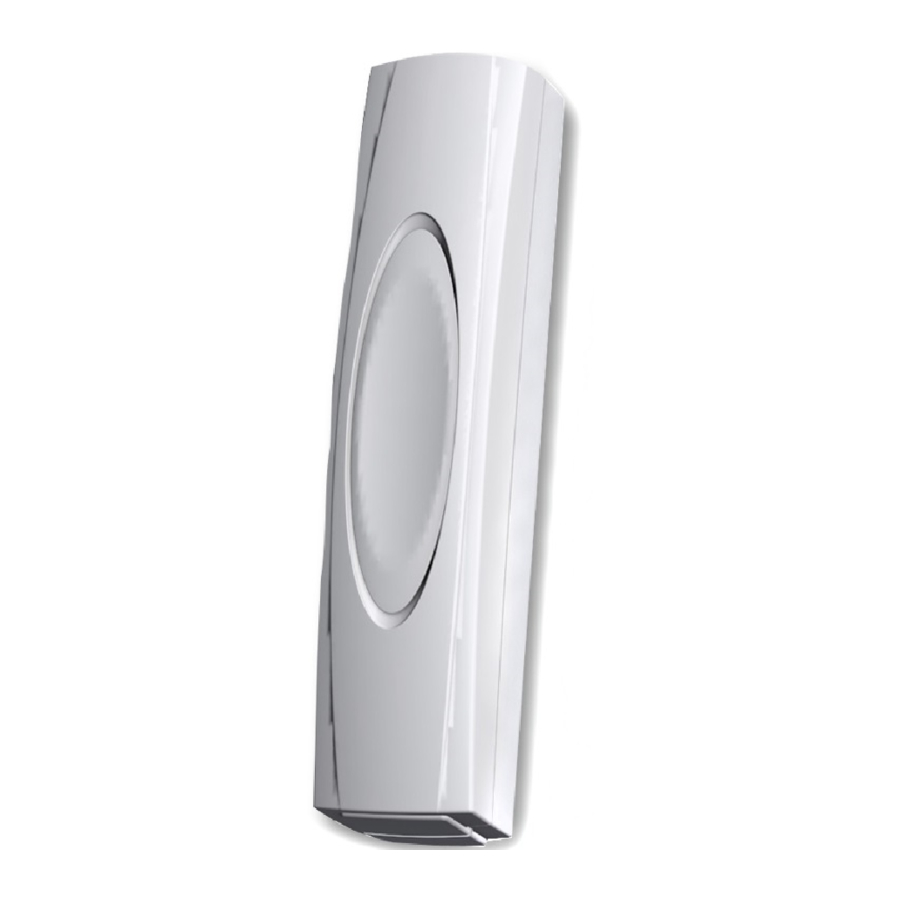
Texecom Premier Elite Impaq Plus-W - Security Sensor Manual
- Instruction manual (2 pages) ,
- Quick start manual (3 pages)
Advertisement

INTRODUCTION
- For wireless connectivity, detailed programming and system set-up instructions please refer to the compatible RICOCHET™ technology enabled Premier wireless expander instructions.
- Featuring RICOCHET™ wireless technology the Impaq Plus-W is designed for professional security installations.
MOUNTING POSITIONS

MOUNTING WITH MAGNET

| Magnets can be installed either side of the unit. | ||
| Material | Approach | Removal |
| Non-Ferrous +/- 4mm | X = 18mm Y = 10mm Z = 22mm | X = 20mm Y = 12mm Z = 24mm |
| Ferrous +/- 3mm | X = 8mm Y = 8mm Z = 16mm | X = 9mm Y = 9mm Z = 18mm |
ASSEMBLY
For rear tamper - fix both the detector AND the rear tamper insert to the mounting surface. Activation of rear tamper will damage product.

SENSITIVITY SET-UP
The Impaq Plus-W can be installed in any orientation but for maximum sensitivity position as shown in Fig.2. Once mounted the sensitivity should be carefully calibrated using range jumper and the sensitivity adjustment.
- When the unit is first powered the LED will light green for approximately 10 seconds while the unit self-calibrates.
- Enable walktest LED functionality using wireless monitor/Wintex. To set the sensitivity turn the sensitivity adjustment to minimum (anti-clockwise) and firmly tap the middle of the area to be protected. If the LED lights red or orange, remove the "Range Select" jumper to select the "low sensitivity" range. Gradually increase the sensitivity by turning the sensitivity adjustment clockwise. After each adjustment, firmly tap the area and observe the LED colour. A red LED indicates that the sensitivity is correct. If the LED turns green, the sensitivity is too low and needs increasing. If however the LED turns orange, the sensitivity is too high and needs reducing.
- Replace the cover and tighten the fixing screw. Press the cover into the lid and confirm the desired impact response.
PARTS

Battery
Only replace with 3V Lithium CR123A.
Battery Safety
- Do not throw into a fire
- Do not heat
- Do not charge
- Do not short circuit
- Do not disassemble
- Replace only with same or equivalent type
- Always observe local regulations when disposing of a battery
- Detector will transmit low battery warning when battery needs replacing
Magnet
Non-Ferrous Mounting Material
- Maximum Break = 30mm
- Minimum Make = 15mm
Ferrous Mounting Material
- Maximum Break = 15mm
- Minimum Make = 5mm
Note: Values depend on mounting material. See Fig.3
Reed Disable
 | Disabled |
 | Enabled |
Range
 | High Range |
 | Low Range |
Relearn
Place jumper on Relearn pin header and insert battery to learn device.
LED STATUS INDICATION
Only available in walktest mode
(See Premier wireless expander instructions)
| Flashing Green: | Comfort LED. When the reed switch is closed, the comfort LED will flash green approximately every 3 seconds to indicate correct operation. | ||
| Momentary Green: | Background disturbance/under-sensitive setting. This is used to indicate background disturbances or an under-sensitive setting during installation. | ||
| Momentary Red: | Alarm condition/correct sensitivity. This is used to indicate that an attack has been detected by the shock sensor or a correct sensitivity setting during installation. | ||
| Momentary Orange: | Gross attack/over-sensitive condition. This is used to indicate that a massive attack has been detected by the shock sensor or an oversensitive setting during installation. | ||

STANDARDS
| Alarm Systems: | EN50131-2-2, EN50131-5-3, EN50131-1, PD6662, Grade 2 Class II |
| EMC: | EN50130-4:1995: A1: A2 ETSI EN301 489-03 V1.4.1 |
| R&TTE: | ETSI EN300-220 (V2.1.1) |
| Environmental: | EN50130-5 |
| Frequency Band: | 868.0 - 868.6 MHz / 433.05 - 434.79 MHz
|
| Product Type: | GBB1000-2 Frequency 868MHz GBB2000* Frequency 433MHz |
| Receiver: | Category 1, Class 2 |
| Receiver LBT (Listen Before Talk) | Yes |
| Transmitter Duty Cycle | 868Mhz<1%, 433Mhz<10% |
| Low Voltage Signal | 2.85V |
| Operating Voltage | 3V |
*GCC2000 is not INCERT approved

Documents / ResourcesDownload manual
Here you can download full pdf version of manual, it may contain additional safety instructions, warranty information, FCC rules, etc.
Download Texecom Premier Elite Impaq Plus-W - Security Sensor Manual
Advertisement


Need help?
Do you have a question about the Premier Elite Impaq Plus-W and is the answer not in the manual?
Questions and answers