Advertisement
Installation Sheet
Description
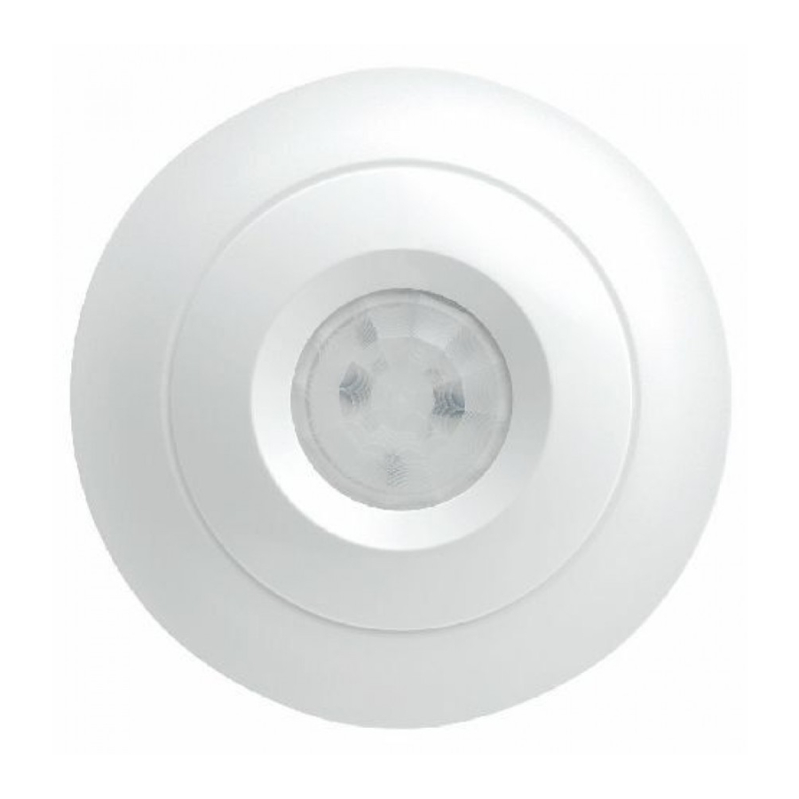
The Premier 360 DT is a ceiling mount PIR detector, which is designed to detect a movement of an intruder, and to activate an alarm on a control panel.
The product must be connected to a listed burglar system compatible control unit or power supply unit, which provides a supply voltage between 9 and 15 V DC as well as a minimum 4 hours of standby power.
The Premier 360 DT is not suitable for outdoor use.
Figure 1

Figure 2

Figure 3

Figure 4

Figure 5
Figure 6

Figure 7

| Figure legends | |||
| Item | Description | Item | Description |
| Fig 2 | Fig. 5 | ||
| | Cable entry | | Tamper relay |
| | Screw | | Alarm relay |
| | Supply connector for 0 V and 12 V | ||
| | First to Alarm/Latch Input | ||
| | Remote LED | ||
| Fig 3 | Fig 6 | ||
| | Tamper jumper | | Selectable EOL configuration |
| | Alarm jumper | | Double Pole (jumper links not used) |
| | LED jumper | | Dual End-of-Line (DEOL) |
| | Pulse count jumper | ||
| | Pulse Count 1 | ||
| | Pulse Count 2 | ||
| Panel Support | Texecom | Cooper Menvier | Honeywell | DSC |
| Alarm EOL | 4K7 | 4K7 | 1K | 5K6 |
| Tamper EOL | 2K2 | 2K2 | 1K | 5K6 |
Installation guidelines
The technology used in these detectors resists false alarm hazards. However, avoid potential causes of instability such as:
- Direct sunlight on the detector.
- Heat sources within the detector field of view.
- Strong draughts onto the detector.
- Large animals within the detector field of view.
- Obscuring the detector field of view with large objects, such as furniture.
To install the detector
- Unwind the screw on the side of the detector until loose; the screw will be retained in the product (see Figure 1, item 1).
- Lift detector lid out from the base and off the lugs at the opposite end to the screw (see Figure 1, item 2).
- Fix the base to the ceiling between 2.4 m and 3.6 m (8 and 12 ft) from the floor. For flat mounting use a minimum of 2 screws (DIN 7998) in any of the available positions (see Figure 2).
- Wire the detector (see Figures 3,5 and 6).
- Select the desired jumper settings (see Figure 3). See section "Setting the detector" below for more information.
- Replace lid and tighten screw in base.
Setting the detector
Jumper settings: See Figure 3 for jumper locations in the detector.
Alarm jumper
Off: Alarm in open circuit.
On: End of line resistor.
Tamper jumper
Off: Tamper in open circuit.
On: End of line resistor.
Input invert jumper
Supply: Input normal.
0 V: Input inverted.
Walk test jumper
On: Walk test enabled.
Off: Walk test under input control.
Pulse count jumper
PC1: Pulse count 1, high sensitivity as required by EN 50131-2-2.
PC2: Pulse count 2, normal sensitivity. Required for CUL installations.
LED indication
| State | Red LED | Alarm relay | To reset |
| Startup | Normal blinking (1Hz) | Closed | Automatically after 60 s |
| PIR intruder alarm | Continuously on | Open (Alarm) | Automatically after 25 s |
Walk Test
Check the detector operation by powering up the detector and ensure that between 9VDC and 16VDC is supplied to the detector.
Replace the front cover by hooking it on at the top and then clip it closed at the bottom. Allow three minutes for the detector to warm up and stabilise before walk testing. With the Walk Test LED enabled, walk test the area. PIR detection is indicated by the green LED, MW by the orange LED and full alarm by the red LED. During the walktest, the MW range should be adjusted (see Figure 3).
- Always instruct the user not to obstruct the field of view
- Large objects near the detector will reduce coverage
There are several ways that the Walk Test LED can be disabled to prevent unauthorised persons from tracing the coverage pattern.
Latch Input / First to Alarm
- The FTA terminal can perform several different functions depending on how it is connected:
- Latch connected to Set Positive (SW+, Set+): The LEDs will be disabled while the system is set. Any detectors triggered while the system is set will indicate this by permanently lighting the alarm LED (upon unsetting the system).
Detectors can be reset by taking the latch line high and then low again.
- Latch connected to Alarm Positive (AL+, A+ve): The first detector activated while the system is set will indicate this with a slowly flashing alarm LED (upon unsetting the system). Detectors activated subsequently will indicate this by permanently lighting the alarm LED. Detectors can be reset by taking the latch line high and then low again.
Specifications
| Detector | PIR | ||||||
| Signal processing | DSP | ||||||
| Range | Coverage diameter 9.3m at 3.6m mounting height | ||||||
| Optics | Fresnel lens | ||||||
| Power supply | 9 to 15 VDC (15VDC nominal @10.6mA) Power rating: 0.16W | ||||||
| Peak-to-peak ripple | 2 V (at 12 VDC) | ||||||
| Power supply unit | Rated 94HB | ||||||
| Startup time | 60 s | ||||||
| Maximum current | |||||||
| Normal | 8.7 mA | ||||||
| Alarm | 7.5 mA | ||||||
| Maximum | 28 mA | ||||||
| Mounting height | 2.4 to 3.6 m | ||||||
| Target speed range | 30 cm/s to 3 m/s (1 ft./s to 10 ft./s) | ||||||
| Alarm relay | <24 VDC, 50 mA, NC, resistive load 34 Ω max. | ||||||
| Tamper relay | <24 VDC, 50 mA, NC | ||||||
| Alarm time | >2 s | ||||||
| Dimensions (W × H × D) | 116 x 33 × 116 mm | ||||||
| Weight | 125 g | ||||||
| Operating environment | |||||||
| Temperature | −35 to +55°C (-31 to 130°F) | ||||||
| Relative humidity | 0 to 95% noncondensing | ||||||
| Frequency | 24GHz | ||||||
| Maintenance | Yearly test by installer | ||||||
Regulatory information
Supplier:Texecom Ltd, St. Crispin Way, Haslingden, Lancashire, BB4 4PW, UK. Security grade: EN Grade 2
Environmental class: Class II
Standards: EN 50131-2-2
European Directives
2004/108/EC (CE directive): Hereby, Texecom declares that this device is in compliance with the essential requirements and other relevant provisions of Directive 2004/108/EC.

R&TTE Directive: 1999/5/EC
2002/95/EC (RoHS Directive): Hereby, Texecom declares that this device does not contain lead, mercury, cadmium, hexavalent chromium, polybrominated biphenyls (PBB) or polybrominated depheny ethers (PBDE) in more than the percentage specified by EU directive 2002/95/EC, except exemptions stated in EU directive 2002/95/EC annex.

2002/96/EC (WEEE directive): Products marked with this symbol cannot be disposed of as unsorted municipal waste in the European Union. For proper recycling, return this product to your local supplier upon the purchase of equivalent new equipment, or dispose of it at designated collection points. For more information see: www. recyclethis.info.
Maintenance: To be tested yearly by the installer
Warranty: 5 year replacement warranty
The Premier 360 DT is not a complete alarm system, but only its part. Therefore Texecom does not accept any responsibility or liability for any damage that is claimed to be a result of an incorrect functioning of the Premier 360 DT PIR detector. Texecom reserves the right to change the specification without a prior notice.
The Premier Elite detectors are protected by UK & International Registered Designs. Premier Elite is a Trademark of Texecom Ltd. © 2011 Texecom Ltd.
Contact information: www.texe.com


Documents / Resources
References
Download manual
Here you can download full pdf version of manual, it may contain additional safety instructions, warranty information, FCC rules, etc.
Advertisement


Need help?
Do you have a question about the Premier 360 DT and is the answer not in the manual?
Questions and answers