Table of Contents
Advertisement
Change for life
Installation, Startup and Maintenance Manual
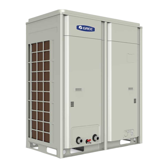
A Series Inverter Modular Air-cooled Chiller (Heat Pump)
Model:
LSQWRF35VM/NhA-M
LSQWRF60VM/NhA-M
LSQWRF130VM/NhA-M
Thank you for choosing commercial air conditioners.Please
read this Owner' s Manual carefully before operation and
If you have lost the Owner's Manual, please contact the
local agent or visit www.gree.com or send an email to
Advertisement
Table of Contents

Related Manuals for Gree LSQWRF130VM/NhA-M


Summary of Contents for Gree LSQWRF130VM/NhA-M
- Page 1 Model: LSQWRF35VM/NhA-M LSQWRF60VM/NhA-M LSQWRF130VM/NhA-M Thank you for choosing commercial air conditioners.Please read this Owner’ s Manual carefully before operation and If you have lost the Owner's Manual, please contact the local agent or visit www.gree.com or send an email to...
- Page 2 To users Thank you for selecting Gree’s product. Please read this instruction manual carefully before installing and using the product, so as to master and correctly use the product. In order to guide you to correctly install and use our product and achieve expected operating effect, we hereby instruct as below: (1) This equipment should be installed, operated or maintained by the qualified servicemen who have had specific training.
-
Page 3: Table Of Contents
Contents Safety notices (Please be sure to abide) ............1 1 General introduction ..................6 1.1 Product features ..................6 1.2 Principle diagrams ..................7 2 Operation range ...................10 3 Outline dimensions ..................10 4 Installation instructions .................12 4.1 Pre-check ....................12 4.2 Acceptance check .................12 4.3 Handling and lifting ................12 4.4 Installation foundation and service space ..........13 4.5 Vibration reduction ................16... - Page 4 7.9 Safety operation of flammable refrigerant ..........35 7.10 Refrigerant charging ................36 7.11 Removal of the compressor ..............36 7.12 Freeze protection ................37 7.13 Routine maintenance ................37 7.14 Precautions ..................38 8 Troubleshooting and after-sales service ............43 8.1 Troubleshooting measures ..............43 8.2 After-sales service ................45 Appendix A: Inspection records prior to commissioning ........46 Appendix B: Trial run and commissioning records ..........47...
-
Page 5: Safety Notices (Please Be Sure To Abide)
A Series Inverter Modular Air-cooled Chiller (Heat Pump) Safety notices (Please be sure to abide) WARNING: If not abide strictly, it may cause severe damage to the unit or the people. NOTE: If not abide strictly, it may cause slight or medium damage to the unit or the people. This sign indicates that the operation must be prohibited. - Page 6 A Series Inverter Modular Air-cooled Chiller (Heat Pump) NOTE • To realize the function of the air conditioner unit, a special refrigerant circulates in the system. The used refrigerant is the fluoride R32, which is specially cleaned. The refrigerant is flammable and inodorous. Furthermore, it can leads to explosion under certain conditions.
- Page 7 A Series Inverter Modular Air-cooled Chiller (Heat Pump) NOTE • Do not install the unit where there is high-intensity magnetic field or it is highly basic or acid or the voltage is quietly unstable. • Do not install the unit where there would be leaked inflammable gas, as it would lead to fire hazards. •...
- Page 8 • Do not do troubleshooting personally, as incorrect troubleshooting would lead to electrocution or fire hazards. Instead, please contact GREE after-sales service center. • When the unit is charged with refrigerant, do not solder or cut any pipeline, fined heat exchanger, shell- and-tube heat exchanger or other containers.
- Page 9 A Series Inverter Modular Air-cooled Chiller (Heat Pump) ! CAUTION • Do operate the unit in accordance with this manual and read it carefully before startup or troubleshooting. • Do turn on or off the unit with the controller. ◆ Safety precaution for handling of the unit WARNING •...
-
Page 10: General Introduction
(32kW, 60kW and 130kW). For the LSQWRF35VM/NhA-M unit, it has only one cooling system; for the LSQWRF60VM/NhA-M unit, it has two independent systems; for the LSQWRF130VM/NhA-M unit, there are four uniform independent systems. Up to 16 single units can be modularized, with cooling capacity ranging from 35kW to 1040kW. -
Page 11: Principle Diagrams
A Series Inverter Modular Air-cooled Chiller (Heat Pump) When one water pump get faulty, the other will be turned on to ensure stable operation of the unit, thus improving the unit adaptability. 1.2 Principle diagrams (1) LSQWRF35VM/NhA-M... - Page 12 A Series Inverter Modular Air-cooled Chiller (Heat Pump) (2) LSQWRF60VM/NhA-M...
- Page 13 A Series Inverter Modular Air-cooled Chiller (Heat Pump) (3) LSQWRF130VM/NhA-M...
-
Page 14: Operation Range
A Series Inverter Modular Air-cooled Chiller (Heat Pump) 2 Operation range Please run the unit under the specified operation range as shown in the table below: ■ R32 Series Water side Air side Item Leaving water Water temperature Ambient DB temperature (°C) difference (°C) temperature (°C) - Page 15 A Series Inverter Modular Air-cooled Chiller (Heat Pump) (2) LSQWRF60VM/NhA-M (unit: mm) Installation hole 2060 Water oulet: G2 male thread Water inlet: G2 male thread Drain valve 2200 (3) LSQWRF130VM/NhA-M (unit: mm) 1650 Water in (Anchor bolt 6-M12) 2040 (Anchor bolt 6-M12) 1930 2305 1980...
-
Page 16: Installation Instructions
A Series Inverter Modular Air-cooled Chiller (Heat Pump) 4 Installation instructions 4.1 Pre-check Installation should be performed by the skilled technician to guarantee the normal operation and prevent malfunctions and please read this manual carefully prior to installation. The chiller is manufactured, inspected and tested strictly in accordance with the quality control program and it will work properly within the expected service life as long as its installation, operation and service. -
Page 17: Installation Foundation And Service Space
During transport by the forklift ,the symmetric holes should be used at the A-A or B-B base of the unit itself, or at the wooden base. (2) LSQWRF130VM/NhA-M The length of the spreader should be larger than that of the unit. - Page 18 A Series Inverter Modular Air-cooled Chiller (Heat Pump) (3) Enough space shall be left for service and ventilation. There should be good ventilation around the unit. Beside, be sure there is at least 1mbetween the unit and any barrier, and at least 1.2m should be kept at the side of the water inlet and outlet pipes.
- Page 19 A Series Inverter Modular Air-cooled Chiller (Heat Pump) Inlet Inlet Inlet Inlet Inlet Inlet Electric box Inlet Inlet Inlet The inlet and outlet pipes both are at this side. Inlet Inlet Inlet Electric box The inlet and outlet pipes both are at this side. Inlet Inlet Inlet...
-
Page 20: Vibration Reduction
A Series Inverter Modular Air-cooled Chiller (Heat Pump) Note: diagrams above are just for reference and not in real proportion. 4.5 Vibration reduction The unit shall be securely attached to the foundation through the mounting hole by following the steps below. -
Page 21: Installation Of The Water System
A Series Inverter Modular Air-cooled Chiller (Heat Pump) 4.7 Installation of the water system ■ Considerations stated below shall be taken carefully for the water system. (1) Each water inlet and outlet should be labeled properly to avoid misconnection. (2) A flexible connector should be used at the chilled water outlet to reduce vibration transmission. (3) A manometer, a thermometer and a gate valve shall be installed at the chilled water inlet/outlet. - Page 22 A Series Inverter Modular Air-cooled Chiller (Heat Pump) ■ Installation illustration...
-
Page 23: Introduction To The Display Panel
A Series Inverter Modular Air-cooled Chiller (Heat Pump) ■ Drainage (1) Loosen screws around the panel and then take down it. (2) Remove anticlockwise the blind plug located at the bottom of the heat exchanger to let the chilled water flow out, after that, tighten the blind plug and reinstall the panel. (Note: place the drainage equipment beneath the drain pipe to prevent pollution caused by the drain water. - Page 24 A Series Inverter Modular Air-cooled Chiller (Heat Pump) Note: the output control lines of the AC contactors for the running indicator, water pump 1, water pump 2, auxiliary electric heater 1, auxiliary electric heater 2 can be wired to the corresponding wiring board of all units, while those for the error indicator and external passive contact switch should be wired to the corresponding wiring board of all units as shown in the figure below.
- Page 25 A Series Inverter Modular Air-cooled Chiller (Heat Pump) Unit 1~16 When multiple modules have direct control over one water pump, its AC contactor is wired to an AC contactor (KM1 or KM2) of any one module. Unit 1 Unit 2 Unit 3 When one auxiliary electric heater serves more than one modules, its wiring terminals 11 and 12 are connected to terminals G and H respectively of an AC contactor marked...
- Page 26 A Series Inverter Modular Air-cooled Chiller (Heat Pump) (2) LSQWRF60VM/NhA-M External passive contact switch error indicating running indicating Note: the output control lines of the AC contactors for the auxiliary electric heater 1, auxiliary electric heater 2 can be wired to the corresponding wiring board of all units, while those for the error indicator and external passive contact switch should be wired to the corresponding wiring board of all units.
- Page 27 A Series Inverter Modular Air-cooled Chiller (Heat Pump) (3) LSQWRF130VM/NhA-M Control output neutral line Control output contactor (electric heater 2; 220V live line) Control output neutral line Control output contactor (electric heater 1; 220V live line) Remote start/stop Remote start/stop Control output neutral line Control output contactor (user water pump 2;...
-
Page 28: Specification Of Power Supply
380V-415V AC 3Ph 50Hz LSQWRF60VM/NhA-M 380V-415V AC 3Ph 50Hz LSQWRF130VM/NhA-M 380V-415V AC 3Ph 50Hz Notes: (a) The specifications of the breaker and power cable listed in the table above are determined based on the maximum power (maximum amps) of the unit. - Page 29 A Series Inverter Modular Air-cooled Chiller (Heat Pump) (2) LSQWRF60VM/NhA-M HL3 6 Water pump (3) LSQWRF130VM/NhA-M...
-
Page 30: Filed Wiring
A Series Inverter Modular Air-cooled Chiller (Heat Pump) 6.4 Filed wiring ■ Safety codes (1) All wiring shall comply with applicable codes and engineering requirements. (2) All field wiring shall be performed by the qualified electrician. (3) Never perform wiring before the power supply is cut off. (4) Any damage caused by the improper external wiring shall be at the installer’s expense. - Page 31 The cable should be fixed with fasteners. LSQWRF130VM/NhA-M (4) The unit shall be grounded reliably and never connect the ground wire with the gas fuel pipe, water pipe, lightening rod or telephone line. (5) After wiring, O-rings should be tightened to prevent coming of insects.
-
Page 32: Networking And Wiring Between Units
A Series Inverter Modular Air-cooled Chiller (Heat Pump) (4) The remote switch control signal is available for the electric box and please pay attention to the input passive dry contact. (5) A reasonable length of the control line should be left outside the unit and the rest should be bundled and fed into the electric box. - Page 33 A Series Inverter Modular Air-cooled Chiller (Heat Pump) (2) LSQWRF60VM/NhA-M, LSQWRF130VM/NhA-M...
-
Page 34: Setup Of Dip Switches On The Motherboard
• Install the remote monitoring software at the PC. • Based on GREE provided Modbus protocol, the user can do second development to this protocol. Note: those enclosed by the dotted lines indicate the remote monitoring equipment. When the quantity of the display panel exceeds 30 or length of the communication line exceeds 800m, extra photoelectric relay is required. -
Page 35: Jumpers
4202021916 QXFS-H80zN345K 7 Commissioning and maintenance The unit shall be maintained periodically by the skilled servicemen from Gree or a designed person under our professional guide to guarantee the unit operates reliably in a long term. 7.1 Check before startup Please finish the following steps before staring the system. - Page 36 A Series Inverter Modular Air-cooled Chiller (Heat Pump) Water quality requirement Cold/hot water Trend Items Circulating Makeup Corrosion Scale water water pH (25°C) 6.8-8.0 6.8-8.0 ○ ○ Electrical μs/cm <400 <300 ○ ○ conductivity (25°C) mg(Cl <50 <50 ○ Basic items mg (SO <50...
-
Page 37: Trial Run
A Series Inverter Modular Air-cooled Chiller (Heat Pump) (5) Stop the unit to drain up waste solution. If impossible, drain it with making up water at the same time until all waster solution has been drained out completely (at this time water is transparent and pH is 7). -
Page 38: Maintenance To The Main Parts
(6) Regulate the water flow through the balance valve and check the water pressure. (7) Check if the fan rotates properly. (8) Check if the system vibration and noise are acceptable. 7.8 Parts replacement Only parts supplied by Gree can be replaced instead of similar parts supplied by others. -
Page 39: Safety Operation Of Flammable Refrigerant
A Series Inverter Modular Air-cooled Chiller (Heat Pump) 7.9 Safety operation of flammable refrigerant (1) Qualification requirement for installation and maintenance man All the work men who are engaging in the refrigeration system should bear the valid certification awarded by the authoritative organization and the qualification for dealing with the refrigeration system recognized by this industry. -
Page 40: Refrigerant Charging
A Series Inverter Modular Air-cooled Chiller (Heat Pump) 7.10 Refrigerant charging Refrigerant charging should be done based on the discharge and suction pressure. An air tight test must be taken on the condition refrigerant leaks or some part is required to be replaced. Refrigerant charging comes into two cases stated below. -
Page 41: Freeze Protection
A Series Inverter Modular Air-cooled Chiller (Heat Pump) 7.12 Freeze protection When the flow passage of the shell-and-tube heat exchanger is frozen up, it would cause serious damage to the heat exchanger, such as cracking and leakage which are out of warranty, therefore, the user should take measures stated below for freeze protection: (1) In order to make sure the unit can automatically perform defrosting under low temperature, the water pump must be interlocked with the unit. -
Page 42: Precautions
A Series Inverter Modular Air-cooled Chiller (Heat Pump) ■ Quarterly Maintenance (1) Check the electric wiring and electric insulation. (2) Check and adjust the set point of the temperature. ■ Yearly Maintenance (1) Check valves and pipeline of the water system. If necessary, clean the filter and analyze the water quality. - Page 43 A Series Inverter Modular Air-cooled Chiller (Heat Pump) ■ General work area All maintenance staff and others working in the local area shall be instructed on the nature of work being carried out. Work in confined spaces shall be avoided. The area around the workspace shall be sectioned off.
- Page 44 A Series Inverter Modular Air-cooled Chiller (Heat Pump) ■ Checks on electrical devices Repair and maintenance to electrical components shall include initial safety checks and component inspection procedures. If a fault exists that could compromise safety, then no electrical supply shall be connected to the circuit until it is satisfactorily dealt with.
- Page 45 A Series Inverter Modular Air-cooled Chiller (Heat Pump) ■ Leak detection methods The following leak detection methods are deemed acceptable for systems containing flammable refrigerants. Electronic leak detectors shall be used to detect flammable refrigerants, but the sensitivity may not be adequate, or may need re-calibration.
- Page 46 A Series Inverter Modular Air-cooled Chiller (Heat Pump) (5) Extreme care shall be taken not to overfill the refrigeration system. Prior to recharging the system it shall be pressure tested with OFN. The system shall be leak tested on completion of charging but prior to commissioning. A follow up leak test shall be carried out prior to leaving the site.
-
Page 47: Troubleshooting And After-Sales Service
A Series Inverter Modular Air-cooled Chiller (Heat Pump) The recovery equipment shall be in good working order with a set of instructions concerning the equipment that is at hand and shall be suitable for the recovery of flammable refrigerants. In addition, a set of calibrated weighing scales shall be available and in good working order. - Page 48 A Series Inverter Modular Air-cooled Chiller (Heat Pump) Symptoms Probable causes Recommended action 1. Replace the coils or even the 1. The electrostatic expansion valve is valve body. faulty. 2. Check the low pressure Shutdown against low 2. The low pressure cutoff is faulty. cutoff.
-
Page 49: After-Sales Service
A Series Inverter Modular Air-cooled Chiller (Heat Pump) Symptoms Probable causes Recommended action 1. Decrease the load to improve 1. Too low water temperature. the water temperature. Failed diischarge 2. The discharge temperature sensor 2. Check if the discharge temperature sensor fell off. -
Page 50: Appendix A: Inspection Records Prior To Commissioning
A Series Inverter Modular Air-cooled Chiller (Heat Pump) Appendix A: Inspection records prior to commissioning Installation Routine check... -
Page 51: Appendix B: Trial Run And Commissioning Records
A Series Inverter Modular Air-cooled Chiller (Heat Pump) Appendix B: Trial run and commissioning records Trial run Commissioning... - Page 52 GREE ELECTRIC APPLIANCES, INC. OF ZHUHAI Add: West Jinji Rd, Qianshan, Zhuhai,Guangdong, China, 519070 Tel: (+86-756) 8522218 Fax: (+86-756) 8669426 E-mail: global@cn.gree.com www.gree.com...
Need help?
Do you have a question about the LSQWRF130VM/NhA-M and is the answer not in the manual?
Questions and answers