Sign In
Upload
Manuals
Brands
Leadshine Manuals
Servo Drives
2ELD2-CAN Series
Leadshine 2ELD2-CAN Series Manuals
Manuals and User Guides for Leadshine 2ELD2-CAN Series. We have
2
Leadshine 2ELD2-CAN Series manuals available for free PDF download: User Manual
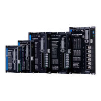
Leadshine 2ELD2-CAN Series User Manual (179 pages)
DC Servo Drive
Brand:
Leadshine
| Category:
Servo Drives
| Size: 4 MB
Table of Contents
Table of Contents
6
Chapter 1 Introduction
9
Product Introduction
9
Model Number Structure
10
Servo Drive
10
Servo Motor
10
Servo Drive Technical Specification
11
Servo Drive Ports and Connectors
12
Motor Ports and Connectors
13
Chapter 2 Installation & Wiring
14
Servo Drive Installation
14
Servo Drive Installation Environment
14
Servo Drive Dimension
14
Servo Motor Installation
17
Installation Conditions
17
Precautions During Installation
17
Eld2-Can Wiring Diagram
18
Servo Drive Ports
19
CN1 I/O Signal Port
21
CN3/CN4 Power Supply & Regenerative Resistor Port
22
CN5 Canopen Communication Port
22
CN6 Safe Torque off (STO) Port
23
CN7 RS232 Tuning Port
24
CN9 Logic Circuit Power Supply Port
25
ENC Encoder Feedback Port
25
ID Spin Dial RSC
26
Baud Rate/Terminal Resistor Switch SW
26
Cable Selection
27
Motor Power Cable
27
Motor Encoder Cable
30
Motor Brake Cable
31
Drive Communication Cable
32
Tuning Cable
32
Regenerative Resistor Selection
33
Chapter 3 Parameter
37
Parameter List
37
Servo Drive Parameter
37
Motion Parameter Starting with Object Dictionary 6000
43
Parameter Function
45
Class 0】Basic Settings
45
Class 1】Gain Adjustments
49
Class 2】Vibration Suppression
56
Class 3】Velocity/ Torque Control
61
Class 4】I/O Interface Setting
63
Class 5】Extension Settings
69
Class 6 】 Other Settings
73
Parameters Function
77
Chapter 4 Control Mode
89
Profile Position Mode
89
Pulse
89
Motion Settings
89
Monitoring Settings
90
Applications Example
90
Profile Velocity Mode
91
Motion Settings
91
Monitoring Settings
91
Profile Torque Mode
92
Motion Settings
92
Monitoring Settings
92
Homing Mode
93
Motion Settings
93
Monitoring Settings
93
Homing Mode
94
Emergency Stop
119
Motion Settings
119
Monitoring Settings
119
Chapter 5 Applications
120
Trial Run
120
Inertia Ratio Measuring
121
Notch Filter (Vibration Suppression)
123
Auto Gain Adjustment
125
Rd Gain Switching
127
Friction Compensation Function
129
Regenerative Resistor Settings
130
Safety Functions
131
Max. Motor Rotational Speed Limitation
131
Max. Duration for Motor to Stop after Disabling
131
External Brake Deactivation Output Signal BRK-OFF
132
Servo Stopping Mode
133
Emergency Stop Function
134
Multiturn Absolute Encoder
135
Parameter Settings
135
Read Absolute Position
136
Absolute Encoder Related Alarm
138
Chapter 6 Canopen Communication
139
Communication Connection
139
Canopen Communication Parameters and Ports
139
Canopen Communication Protocol
141
Predefined Connections
141
Object Dictionary
142
Object Dictionary Structure
143
Object Type
143
Access Attribute
143
Network Management (Nmt)
144
NMT Module Control
144
NMT Node Guarding
144
NMT Boot-Up
145
NMT Communication Status Machine
145
Process Data Object (Pdo)
146
Service Data Object
149
Emergency Object
150
Chapter 7 Warning and Alarm
151
Servo Drive Alarm Overview
151
Alarm Handling
156
Cause
159
Error Main Sub Code Cause
159
Diagnosis
159
Display: "Er 0D0
159
Display: "Er 0D2
159
Replace Driver
160
Solution
160
Replace Driver
161
Solution
161
Canopen Communication Alarm
168
Alarm Clearing
178
Servo Drive Alarm Clearing
178
Contact Us
179
Advertisement
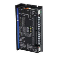
Leadshine 2ELD2-CAN Series User Manual (122 pages)
Brand:
Leadshine
| Category:
Servo Drives
| Size: 2 MB
Table of Contents
Introduction
3
Table of Contents
5
Chapter 1 Introduction
9
Product Introduction
9
Specification and Feature
10
Part Numbering Information
10
Inspection of Product
11
Chapter 2 Installation
11
Storage and Installation Circumstance
11
Servo Drive Installation
12
Installation Method
12
Installation Space
13
Servo Motor Installation
13
Chapter 3 Wiring
14
Wiring
14
Wire Gauge
14
Wiring
16
Drive Terminals Function
17
Power Terminal - Axis 1 and Axis 2
17
Encoder Input Port- Axis 1 or Axis 2
17
Control Signal Port -I/O - Axis 1 and Axis 2
18
Communication Port
19
CAN Bus Connector
19
STO Connector
19
CAN Node-ID and Baud Rate Switch
20
I/O Interface Principle
21
Digital Input Interface
21
Digital Output Interface
21
Chapter 4 Parameter
24
Parameter List
24
Drive Parameters (Group 2000H)
24
Manufacturer Parameters (Group 5000H)
27
Device Profile Parameters (Group 6000H)
29
Parameters Function
32
Class 0】Basic Setting
32
Class 1】Gain Adjust
35
Class 2】Vibration Suppression
40
Class 3】Velocity/ Torque Control
42
Class 4】I/F Monitor Setting
43
Class 5】Extended Setup
48
Class 6】Special Setup
51
Class 7】Factory Setting
54
Parameters Function
55
Chapter 5 Canopen
60
CAN Interface
60
Canopen Protocol
60
Canopen Frame
61
Canopen Objects
62
Nmt
62
NMT Services
64
NMT Error Control
64
Sdo
66
Pdo
67
Sync
68
Emcy
68
Chapter 6 Trial Run
69
Inspection before Trial Run
69
Inspection on Wiring
69
Holding Brake
70
Inspection on Parameters Setting
70
2ELD2-CAN Motion Control Procedure
70
CIA 402 State Machine
71
Common Functions for All Modes
72
Motor Rotation Direction
72
Drive Stop
72
Electronic Gear Ratio
72
Control Word
73
Status Word
74
Drive Enable
75
Profile Position Mode
75
Controlword in Profile Position Mode
76
Statusword in Profile Position Mode
76
Related Objects
77
Example of Profile Position Mode
77
Profile Velocity Mode
78
Controlword in Profile Velocity Mode
78
Statusword in Profile Velocity Mode
78
Related Objects
79
Example of Profile Velocity Mode
79
Profile Torque Mode
80
Controlword in Profile Torque Mode
80
Statusword in Profile Torque Mode
80
Related Objects
81
Example of Profile Torque Mode
81
Homing Mode
82
Controlword in Profile Homing Mode
82
Statusword in Profile Homing Mode
82
Related Objects
83
Example of Homing Mode
83
Homing Method
84
Chapter 7 Application Functions
99
Security Features
99
STO Function
99
BRK-OFF Output
101
Servo Stop Mode
102
Emergency Stop Function
102
Two-Axis Alarm Correlation Function
103
Inertia Ratio Identification
103
On-Line Inertia Ratio Identification
103
Motion Studio Inertia Ratio Identification
103
Vibration Suppression
104
Friction Torque Compensation
106
Regenerative Resister Setting
106
Multi-Turn Absolute Encoder
108
Parameters Setting
108
Read Absolute Position
109
Alarm
110
Chapter 8 Alarm and Processing
111
Alarm List
111
Alarm Processing Method
113
Chapter 9 Product Accessory
121
Accessory Selection
121
Contact Us
122
Advertisement
Related Products
Leadshine 2ELD2-CAN7020B
Leadshine 2ELD2-CAN7030B
Leadshine 2EM3EIP Series
Leadshine 2EM3EIP-522
Leadshine 2EM3EIP-556
Leadshine 2EM3EIP-870
Leadshine 2EM3E Series
Leadshine 2EM3E-522
Leadshine 2EM3E-556
Leadshine 2EM3E-870
Leadshine Categories
DC Drives
Servo Drives
Control Unit
Engine
Controller
More Leadshine Manuals
Login
Sign In
OR
Sign in with Facebook
Sign in with Google
Upload manual
Upload from disk
Upload from URL