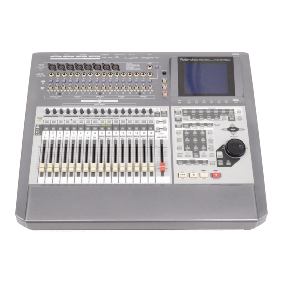
Roland VS-2480 User Manual
Digital studio workstation
Hide thumbs
Also See for VS-2480:
- Owner's manual (452 pages) ,
- Supplementary manual (132 pages) ,
- Owner's manual addendum (92 pages)
Table of Contents
Advertisement
Version 2.0
USER GUIDE
q
Before using this unit, carefully read the sections entitled: "IMPORTANT
SAFETY INSTRUCTIONS" (Owner's Manual p. 2), "USING THE UNIT SAFELY"
(Owner's Manual p. 3, 4), and "IMPORTANT NOTES" (Owner's Manual p. 5).
These sections provide important information concerning the proper operation of
the unit. Additionally, in order to feel assured that you have gained a good grasp of
every feature provided by your new unit, User Guide, Owner's Manual, and
Appendices should be read in their entirety. The manual should be saved and kept
on hand as a convenient reference.
Copyright © 2002 ROLAND CORPORATION
All rights reserved. No part of this publication may be reproduced in any form
without the written permission of ROLAND CORPORATION.
Roland Web site http://www.roland.co.jp/
Advertisement
Table of Contents

Related Manuals for Roland VS-2480


Summary of Contents for Roland VS-2480
- Page 1 Appendices should be read in their entirety. The manual should be saved and kept on hand as a convenient reference. Copyright © 2002 ROLAND CORPORATION All rights reserved. No part of this publication may be reproduced in any form without the written permission of ROLAND CORPORATION. Roland Web site http://www.roland.co.jp/...
-
Page 3: Table Of Contents
Contents Contents ...3 Preparations ...5 Required Preparations ... 5 Installing an Internal Hard Disk ... 5 Cautions When Installing a Hard Disk... 5 Installation de dispositifs optionnels (French language for Canadian Safety Standard)... 8 Précautions à prendre lors de l’installation de dispositifs optionnels ... 8 Installer un disque dur (série HDP35) ... - Page 4 Contents Using Effects ...50 Selecting the effect patch you wish to use ... 50 Selecting the effect bus assignment ... 52 Applying a Loop Type Effect During Playback... 53 Applying a Loop Type Effect Only to the Monitor Sound as You Record ... 55 Switching Effects During Playback...
-
Page 5: Preparations
In some countries, VS-2480’s do not come with the Hard Disk installed. A Roland HDP35 series hard disk (sold separately in some countries) can be installed in the VS-2480. In order to take full advantage of the VS-2480’s functionality for the number of tracks that can be recorded/played back simultaneously, we recommend that you install the HDP35-40G or higher model. - Page 6 With the warning label of the hard disk facing upward, slide it gently into the installation bay as far as it will go. You can hook the indentation of the attachment hardware over the protrusion on the chassis of the VS-2480. fig.01-03_40 After you install the hard disk to the unit you use, please lock it to fix.
- Page 7 As described in “Turning On the Power (p. 19),” turn on the power and verify that the VS-2480 starts up correctly. If the Display Indicates “Not Found any Drives” The internal hard disk was not recognized correctly. Use the rear panel power switch to turn off the power (p.
-
Page 8: Installation De Dispositifs Optionnels (French Language For Canadian Safety Standard)
•Conservez le sachet d’origine dans lequel était la carte lors de l’envoi et remettez la carte dedans si vous devez la ranger ou la transporter. • Veillez à ne pas laisser tomber de vis dans le châssis du VS-2480. • Ne pas toucher aux circuits imprimés ou aux connecteurs. - Page 9 Orienter le disque dur de façon à ce que la face sur laquelle est collée l’étiquette de mise en garde se trouve sur le dessus. Après avoir installé le disque dur dans le VS-2480, fixez-le bien afin qu'il ne se détache pas.
- Page 10 Preparations Pour ce faire, insérez une pièce de monnaie dans la fente et tournez dans le sens des aiguilles d'une montre jusqu'à ce que vous entendiez un déclic. Cela signifie que le disque est bien fixé. Les vis peuvent s’enlever avec les doigts. Si elles sont trop serrées pour être dévissées avec les doigts, vous pouvez utiliser une pièce de monnaie.
-
Page 11: Installing Effect Expansion Boards
Before installing the VS8F-2, turn off the power of the VS-2480/2480CD and all connected devices, and disconnect all cables from the VS-2480/2480CD. Turn the VS-2480/2480CD on its back, and remove only the screws shown in the following diagram. loosen tighten... - Page 12 Connect the cables that you disconnected earlier. Turn on the power, as described in “Turning On the Power (p. 19).” After proper startup of the VS-2480/2480CD, press [EFFECT] and confirm that the FX 1 and 2 icons are displayed. If two VS8F-2 units are installed, press [EFFECT] and confirm that the icons for FX 1–4 are displayed.
- Page 13 fig.01-09(FXAssign) If the Display Indicates “No EFFECT Board” The internal effect expansion board was not detected correctly. Turn off the power (Shutdown operation), as described in “Turning Off the Power (p. 23),” and re-install the effect expansion board correctly. Preparations...
-
Page 14: Installation De La Carte D'extension D'effets (French Language For Canadian Safety Standard)
●Lors de l’insertion de la carte d’extension d’effets, enlevez seulement les vis indiquées dans les instructions. ●Veillez à ne pas laisser tomber de vis dans le châssis du VS-2480/2480CD. ●Ne pas laisser le panneau de protection avant détaché. S’assurer de l’avoir rattacher après avoir installé... - Page 15 A l’intérieur se trouvent deux connecteurs et 12 goupilles de plastique. Reliez les connecteurs de la VS8F-2 à ceux du VS-2480/2480CD tout en insérant les goupilles de plastique dans les orifices de la VS8F-2. fig.1-05.f Reposez le couvercle en remettant les vis enlevées (comme spécifié) à...
-
Page 16: How To Replace The Battery
Before changing the lithium battery, store the current project (p. 49). Turn off the power of VS-2480/2480CD and all connected devices, and disconnect all cables from VS-2480/2480CD. Turn the VS-2480/2480CD on its back, and remove only the screws shown in the following diagram. fig.01-10a_50... - Page 17 fig.battery1_69 The battery should now be visible, as shown in the following. fig.battery2_69 CR2032 CR2032 If Effect Expansion Board (VS8F-2) installed on the EFFECT A section, remove the VS8F-2 of the EFFECT A section. Replace the old battery with a new one. Preparations When turning the unit upside-down, get a bunch...
-
Page 18: Basic Connections (Power Supply, Audio Devices And Headphones)
2 jack. The PHONES jack will output the same signal as the MONITOR jacks. When you purchase the VS-2480/2480CD, it will be set so that all analog audio signals are output from the MASTER jacks. The MONITOR jacks will output the same sound as the MASTER jacks. -
Page 19: Turning On The Power
The VS-2480/2480CD Support the “Mouse” and the “VGA Monitor” The VS-2480/2480CD has a “Mouse connector” that allows a mouse to be connected. If a mouse is connected, you will be able to use a mouse to operate the buttons and control knobs that appear in the display of the VS-2480/2480CD. -
Page 20: Adjusting The Display Contrast
■ Adjusting the Display Contrast fig.01-14_50 The text or icons in the VS-2480/2480CD’s display (Operation Display) may be difficult to read immediately after the unit is turned on or after it has been used for long periods, or depending on the environment in which the unit is used. - Page 21 fig.01-17_50 PAGE ROUTING COPY MOVE TRIM IN PATCH BAY COPY MOVE INSERT AUTOMIX A.PUNCH MENU CD-RW PROJECT TRACK EFFECT MASTERING LOCATOR / MARKER / SCENE LOCATOR BANK AUX 7 AUX 8 USER MARKER AUX 4 AUX 5 AUX 6 AUX 1 AUX 2 AUX 3 PREVIOUS...
-
Page 22: Setting The Date And Time Of The Internal Clock
Setting the Date and Time of the Internal Clock The VS-2480/2480CD contains a clock. When you record a performance, a time stamp is added which indicates the date and time of the recording. This is a convenience that helps you keep track of the date or order in which recordings were made. -
Page 23: Turning Off The Power
Turning Off the Power If you simply turn off the power, not only can recorded content be lost, but the VS-2480/2480CD itself could malfunction. In order to safeguard the recorded performance and turn off the power safely, you must perform the Shutdown procedure when you are finished. - Page 24 Lower the volume of your audio equipment. Turn off the power of your audio equipment. Use the rear panel POWER switch to turn off the VS-2480/2480CD. If “STORE Current?” is Displayed When you execute various operations (including Shutdown), “STORE Current?”...
-
Page 25: Listening To The Demo Performance
CD-R/RW drive such as the Roland CD Recorder is necessary to the Recover. For details please see the leaflet “To Recover the demo performance” of a belonging. If you are using a VS-2480 that does not have an internal CD-RW drive, you will need a separately sold CD-RW drive (Roland CD Recorder). - Page 26 Listening to the Demo Performance projects. 11. Select the recovery-destination. Press [F4 (SelDrv)]. Use the TIME/VALUE dial to move the cursor to the recovery-destination, and press [F5 (SELECT)]. If you change your mind about the drive selection, press [F6 (CANCEL)]. 12.
-
Page 27: For Making The Preparations Which Listen To A Demo Performance (Project Select)
For Making the Preparations Which Listen to a Demo Performance (Project Select) Select a demo song, when you listen to a demo performance. Use the following procedure to select a project. fig.2-05 Press [PROJECT]. Project List screen appears. Use the TIME/VALUE dial to move the cursor to the project that you want to listen to the demo project. -
Page 28: Playing Back The Demo Performance
Listening to the Demo Performance Playing Back the Demo Performance fig.02-01_30 FROM TRACK PLAY PHRASE (dB) Press [TR 1-16 (MASTER EDIT)]. [TR 1-16 (MASTER EDIT)] indicator will light, the channel fader will adjust to the Track Mixer level of channel 1–16. fig.02-02_50 Set the MONITOR knob to the 0 dB position (3 o’clock). -
Page 29: Adjusting The Overall Volume
Press [F6 (To Pre)] to select pre level display, and press [F6 (To Pst)] once again to select post level display, alternately (except from the INPUT display or OUTPUT display). The upper part of the level meter will indicate whether the current display is the pre level or the post level. -
Page 30: Listening To The Demo Performance With A Different Arrangement (Scene)
0. Of the [0]–[9] buttons, press any that has a lighted indicator. The scene will be recalled, and the settings of the VS-2480/2480CD will change. Press [PLAY]. The project will playback. Notice that the arrangement of the demo performance is different. -
Page 31: Making A Multi-Track Recording
Making a Multi-Track Recording This chapter explains the basic procedure for recording on the VS-2480/2480CD. Please follow through these steps to understand the procedure. Creating a New Project (Project New) Regarding Hard Disk Partition Size When purchased, the hard disk (HDP35 series) is divided (partitioned) into 10 GB units. - Page 32 Making a Multi-Track Recording fig.03-01_50 Use TIME/VALUE dial to select the Sample Rate (96kHz, 88.2kHz, 64kHz, 48kHz, 44.1kHz, 32kHz). Normally, choose “44.1k.” Press [ ] to move the cursor to “Record Mode.” Use TIME/VALUE dial to select the Recording Mode (M24, MTP, CDR, M16, MT1, MT2, LIV, LV2).
-
Page 33: Connecting Microphones
One mic will record an acoustic guitar, and the other mic will record the vocal. fig.03-02_35 Lower the master fader of the VS-2480/2480CD to the minimum position. Connect the microphones to the INPUT jacks. XLR jack mics can be connected to INPUT 1 through INPUT 8, and phone jack mics can be connected to INPUT 1–INPUT 16. -
Page 34: Cautions When Connecting Microphones
Move the microphone away from the speaker Lower the volume • The power of the VS-2480/2480CD must be turned off before you switch the phantom power on/off. If the phantom power is switched on/off when the VS-2480/2480CD is on, a loud noise will be output, which could damage your amp or speakers. -
Page 35: Adjusting The Input Sensitivity
Adjusting the Input Sensitivity fig.03-06_50 PAGE Press [HOME (DISPLAY)]. Home Condition screen will appear. Press [PAGE] several times until “INPUT” will be appeared at the [F1]. Press [F1 (INPUT)]. At this time, the level meters will show the volume level of the input source. fig.03-07_30 COLD (SLEEVE) -
Page 36: Recording On A Track
Making a Multi-Track Recording Recording On a Track This section explains the procedure for using a mic connected to the ANALOG INPUT 1 jack to record an acoustic guitar performance to track 1. fig.03-06_50 PAGE Press [HOME (DISPLAY)]. Home Condition screen will appear. fig.03-11_30 RATIO THRESHOLD... - Page 37 fig.QuickRouting Press [F4 (AllClr)]. Press [IN 1-16 (SOLO)]. [IN 1-16 (SOLO)] indicator will light, and channel fader will adjust the Input Mixer channel 1–16. Specify the recorded on which source. Press [SELECT] of the source channel that you wish to record. For this example, Press Input Mixer Channel 1 [SELECT].
-
Page 38: Playing Back The Performance You Recorded
Making a Multi-Track Recording Playing Back the Performance You Recorded Now let’s playback the performance that was recorded on track 1. fig.03-14_30 RATIO THRESHOLD ATTACK RELEASE LEVEL FREQ Dynamics Filter PHRASE SEQ / AUTOMIX CH EDIT MANUAL WRITE READ FROM TRACK PLAY PHRASE... -
Page 39: Canceling The Recording
Canceling the Recording ■ Canceling a Record Result (Undo) If the recording level was too low, if you made a mistake in your performance, or if for any other reason you wish to re-do the recording, you can use the following procedure to cancel the contents of the recording. -
Page 40: Re-Recording A Specified Portion (Punch-In/Punch-Out)
Making a Multi-Track Recording ■ Re-Recording a Specified Portion (Punch-In/Punch-Out) When you listen to a performance that you recorded, you may notice that even though the overall performance is good, a mistake was made or the wrong lyrics were sung in just one location. In such cases you can use the following procedure to re-record just the portion in which the mistake occurred. -
Page 41: Erasing Just A Portion Of A Recording (Track Erase)
Use the channel faders and master fader to adjust the volume to a comfortable level. ■ Erasing Just a Portion of a Recording (Track Erase) If instead of re-recording the portion where a mistake was made, you simply wish to erase the mistake, use the following procedure. -
Page 42: Recording On A V.track
Making a Multi-Track Recording Recording On a V.Track The VS-2480/2480CD has 24 tracks, and each of these tracks has 16 supplementary tracks called V.Tracks. By using these V.Tracks you can record up to 384 (24 x 16) tracks of audio. -
Page 43: Comparing The Recorded Content Of Two V.tracks
Comparing the Recorded content of Two V.Tracks If you have been following the procedures in the previous examples, V.Tracks 1 and 2 of track 1 contain recorded performances. Here’s how you can compare the performances of the two V.Tracks. fig.03-25 Press [TR 1-16 (MASTER EDIT)]. -
Page 44: Recording On Other Tracks (Overdubbing)
Making a Multi-Track Recording Recording On Other Tracks (Overdubbing) The VS-2480/2480CD allows you to record new performances on other tracks while you listen to the playback of previously recorded tracks. This process is called Overdubbing. In the following example we will explain how to use a mic connected to the INPUT 2 jack to record a vocal on track 3 while you listen to the acoustic guitar performance that you recorded earlier on track 1. -
Page 45: Playing Back Two Or More Tracks
fig.03-28_50 Press [REC]. [REC] indicator will blink red. Press [PLAY]. [PLAY] indicator will light green, recording will begin. 10. When you finish recording, press [STOP]. 11. Press [TRACK STATUS] several times until [TRACK STATUS] indicator will light green, or hold [STOP] and press [TRACK STATUS]. fig.03-32_40 Playing Back Two or More Tracks ■... -
Page 46: Adjusting The Stereo Position Of Each Track
Making a Multi-Track Recording ■ Adjusting the Stereo Position of Each Track If you wish to adjust the stereo position (pan) of each track, use the following procedure. fig.03-34 Press [TR 1-16 (MASTER EDIT)]. [TR 1-16 (MASTER EDIT)] indicator will light, [TRACK STATUS] will display the status of the Track Mixer channel 1–16. -
Page 47: Use The Filter To Adjusting The Tone Of Each Track
fig.03-34 Press [TR 1-16 (MASTER EDIT)]. [TR 1-16 (MASTER EDIT)] indicator will light, [CH EDIT] will be the Channel Edit button of the Track Mixer channel 1–16. Press [CH EDIT] of the track that you wish to adjust the equalizer. [CH EDIT] indicator will light. fig.03-40_35 RATIO THRESHOLD... - Page 48 Making a Multi-Track Recording fig.03-44_35 RATIO THRESHOLD ATTACK RELEASE LEVEL FREQ Dynamics Filter PHRASE SEQ / AUTOMIX CH EDIT MANUAL WRITE READ FROM TRACK PLAY PHRASE Press [CH EDIT] of the track that you wish to adjust the equalizer. [CH EDIT] indicator will light. Press [PAGE] several times until function tab “Page1”...
-
Page 49: Saving Your Performance (Project Store)
To avoid such accidents, use the following procedure to save your project to disk. When handling important project data or when you have been using the VS-2480/2480CD for an extended period, we recommend that you save your data frequently. fig.03-46_50... -
Page 50: Using Effects
If VS8F-2 effect expansion boards are installed, you can use up to eight stereo effects without needing to connect any external devices to the VS-2480/2480CD. Here’s how to use effects when VS8F-2s have been installed. The VS-2480/2480CD comes equipped with one internal effects expansion board (containing two effects processors). - Page 51 fig.04-01_50 Press [PAGE] several times until function tab “Page1” will display at the front. Press [F1 (FX 1)]. The effect algorithm used by effect 1 (FX 1) will be displayed. LOCATOR fig.fx-patch Press [F1 (PATCH)]. PATCH SELECT will appear. fig.fx-patch Press [F1 (PRESET)].
-
Page 52: Selecting The Effect Bus Assignment
Using Effects Selecting the effect bus assignment When using the effect in a loop configuration, the AUX bus is used as the effect bus. Here we will explain how to assign the effect bus. fig.04-02_55 Press [EZ ROUTING (PATCH BAY)]. Routing View screen will appear. -
Page 53: Applying A Loop Type Effect During Playback
Applying a Loop Type Effect During Playback It is common to apply a send/return type effect such as reverb or delay during playback. The following example shows how you can apply reverb (FX1) to track 1 during playback. fig.04-03_55 PAGE Press [HOME (DISPLAY)]. - Page 54 Using Effects fig.04-04_30 RATIO THRESHOLD ATTACK RELEASE LEVEL FREQ Dynamics Filter PHRASE SEQ / AUTOMIX CH EDIT MANUAL WRITE READ FROM TRACK PLAY PHRASE (dB) Output the signal to AUX 1. Use [ cursor to AUX 1 Send switch, use the TIME/VALUE dial to set the send switch to a setting other than Off.
-
Page 55: Applying A Loop Type Effect Only To The Monitor Sound As You Record
Applying a Loop Type Effect Only to the Monitor Sound as You Record The following example shows how a source connected to the INPUT 1 jack can be recorded on track 2 directly (without effects) while you apply a send/return type effect such as reverb or delay to the monitor sound. - Page 56 Using Effects As described in “Selecting the effect bus assignment (p. 52),” specify which AUX bus will be used as the effect bus. Here we will send the AUX1 signal to the Effect 1 (FX 1). fig.04-08_30 RATIO THRESHOLD ATTACK RELEASE LEVEL FREQ...
-
Page 57: Switching Effects During Playback
Switching Effects During Playback While playing back the project for track 2 that you recorded in “Applying a Loop Type Effect Only to the Monitor Sound as You Record (p. 55),” try switching the effect and listen to the result. fig.04-06_55 Press [HOME (DISPLAY)]. - Page 58 Using Effects Press [TR 17-24/FX RTN (V.FADER)]. [TR 17-24/FX RTN (V.FADER)] indicator will light, channel fader will adjust the Track Mixer channel 17–24 and the Effect 1–8 Return level. Raise and lower the FX1RTN fader. The effect depth will change. Adjust to the desired depth.
-
Page 59: Applying A Loop Type Effect While You Record
Applying a Loop Type Effect While You Record Here we will give an example of how a loop type effect such as reverb can be applied to the source of the INPUT 1 jack, and the direct sound and effect sound recorded together on track 3. - Page 60 Using Effects As described in “Recording On a Track (p. 36)” step 6–9, specify which you wish to assign as the source. For this example, effect return (FX RET) 1 and Input Mixer channel 2 are assigned to the recording track 3. As described in “Selecting the effect bus assignment (p.
-
Page 61: Applying An Insertion-Type Effect During Playback
Applying an Insertion-Type Effect During Playback When playing back an acoustic guitar or vocal, it is common to insert an effect such as “Guitar Multi” or “Vocal Multi.” Here we will give an example of applying an insertion-type effect such as Mic Modeling (FX2) to track 2 during playback. fig.04-17_60 Press [HOME (DISPLAY)]. - Page 62 Using Effects fig.04-17_60 Press [PAGE] several times until PAGE function tab “Page2” will be ROUTING appeared at the PATCH BAY front. AUTOMIX CD-RW MASTERING LOCATOR BANK MARKER SCRUB ZERO STORE fig.04-19-1 Press [F1 (FX Ins)]. Effect Insert screen will appear. Use [ move the cursor to “FX2.”...
- Page 63 ■ Inserting the Same Effect into Another Track as Well If in step 8 you selected “Ins” or “InsS,” that effect cannot be inserted into another channel/track. If you choose “InsL” or “InsR,” you can use the other effect on another channel or track with Insert.
-
Page 64: Applying An Insertion-Type Effect During Recording
Using Effects Applying an Insertion-Type Effect During Recording When recording electric guitar or vocals etc., it is common to insert an effect such as Guitar Multi or Vocal Multi. Here we will describe how you can connect an electric guitar to the GUITAR Hi-Z jack, apply an effect (FX2), and record it on track 1. fig.04-22_35 COAXIAL OPTICAL... - Page 65 PAGE TRACK EDIT ROUTING COPY MOVE TRIM IN TRIM OUT PATCH BAY COPY MOVE INSERT AUTOMIX A.PUNCH FROM MENU CD-RW MASTERING PROJECT TRACK EFFECT UTILITY LOCATOR / MARKER / SCENE LOCATOR SCENE BANK AUX 7 AUX 8 USER BANK MARKER AUX 4 AUX 5 AUX 6...
- Page 66 Using Effects fig.04-25_30 TRACK STATUS / PHRASE PAD TRACK PLAY PHRASE (dB) 12. Raise and lower the channel fader 16, and verify that the volume changes. The Input Mixer channel fader is used to make fine adjustments to the recording level. In order to record with optimal audio quality, the fader should normally be set in the 0 dB position.
-
Page 67: Add Finishing Touches To Your Project
Add Finishing Touches to Your Project Here we will explain the procedure by which a recorded performance can be mixed down on the VS-2480/2480CD to a two-track stereo master, and then recorded as an original audio CD. Combining the Performances of Multiple... - Page 68 Add Finishing Touches to Your Project fig.05-02_30 RATIO THRESHOLD ATTACK RELEASE LEVEL FREQ Dynamics Filter PHRASE SEQ / AUTOMIX CH EDIT MANUAL WRITE READ FROM TRACK PLAY PHRASE Press track channel 7 or 8 [TRACK STATUS] several times until light goes off.
- Page 69 recorded on tracks 7 and 8 just as you hear it. It is best to record at as high a level as possible without allowing the sound to distort. 13. Press [IN 17-24/FX RTN (MUTE)]. [IN 17-24/FX RTN (MUTE)] indicator will light, faders become the adjusting levels for Input Mixer channel 17–24 and effect 1–8.
- Page 70 Add Finishing Touches to Your Project 22. Hold [REC] and press channel 7 or 8 [TRACK STATUS]. fig.05-01_50 ZERO 29,33 STORE 28,35 23. Press [TR 1-16 (MASTER EDIT)]. [TR 1-16 (MASTER EDIT)] indicator will light, channel faders become the Track Mixer level for channel 1–16. 24.
- Page 71 Signal Flow (Routing) fig.05-04 Send (dB) 30. Press [REC]. [REC] indicator will blink red. 31. Press [PLAY]. [PLAY] indicator will light green, and recording will begin. 32. When you finish recording, press [STOP]. The project playback will stop. 33. Press [ZERO]. You will return to the beginning of the project. 34.
-
Page 72: Mixing Down To The Mastering Tracks (Mastering Room)
CD, you can specify two of the VS-2480/2480CD’s tracks as the left track and right track, and write them to a CD-R disc. A performance that has not yet been mixed down must be mixed down to 2-track stereo. - Page 73 Use TIME/VALUE dial to select “On.” A dedicated mastering track will appear. Use [ ] to move the cursor to “STATUS.” Use TIME/VALUE dial to select “Rec.” Allowing you to mix down to the mastering track. A.PUNCH fig.05-09_50 Use [ PROJECT ] to move the LOCATOR / MARKER / SCENE...
- Page 74 Add Finishing Touches to Your Project fig.05-10_35 16. Press [TR 1-16 (MASTER EDIT)]. [TR 1-16 (MASTER EDIT)] indicator will light, and channel faders will adjust the Track Mixer channel 1–16. 17. Hold [STOP], press [TRACK STATUS] for the Track Mixer channel 1–24 which you want to mixdown.
-
Page 75: Playing Back The Mastering Tracks
Signal Flow (Routing) fig.05-11a Track 1--24 (dB) 23. Use the TIME/VALUE dial or the SHUTTLE ring to move to the time location (such as 00h00m00s00f) at which you wish to begin mixdown. 24. Press [REC]. The [REC] indicator will light in red. 25. - Page 76 Add Finishing Touches to Your Project Use [ Use TIME/VALUE dial to select “On.” A dedicated mastering track will appear. Use [ move the cursor to “STATUS.” Use TIME/VALUE dial to select “Play.” A dedicated mastering track will appear, allowing you to playback to the mastering track.
-
Page 77: Erasing An Unwanted Portion (Track Cut)
Erasing an Unwanted Portion (Track Cut) Project data that was track-bounced will be recorded to the CD-R disc starting form “00h00m00s00” of that track and ending at the end of the project (project end). This means that if there are silent portions at the beginning or end of the performance, that capacity of the CD-R disc will be wasted. -
Page 78: Deleting An Unwanted Portion At The End Of The Project
Add Finishing Touches to Your Project Use the TIME/VALUE dial or SHUTTLE ring to move to the time location at which you wish to stop writing. Press [2]. The end time of the project will be registered, and the [2] indicator will light. -
Page 79: Deleting An Unwanted Portion At The Beginning Of The Project
■ Deleting an Unwanted Portion At the beginning of the Project fig.05-08_50 Press [HOME (DISPLAY)]. Home Condition will appear. Press [PHRASE/REGION] in TRACK EDIT several times until indicator light red. Hold [SHIFT] and press [PROJECT TOP (TO)] in PREVIEW. Move to the start time of the region to be erased. -
Page 80: Adding Track Number Markers
Add Finishing Touches to Your Project Adding Track Number Markers By placing two or more projects one after the other in the same track, you can write these projects consecutively to the CD-R disc. In this case, you can place markers between projects to function as track numbers, just as on a pre-recorded audio CD. -
Page 81: Assigning Track Numbers
■ Assigning Track Numbers When you write an audio CD, a track number will automatically be assigned to “00h00m00s00f.” For this reason, the track number markers and the actual project order will be as follows. fig.05-15 00h00m00s00 Marker 1 Song 2 (Second song) Song 1 (First song) When a blank CD-R disc is used If you write additional projects onto a CD-R disc to which projects have already been... -
Page 82: Creating An Original Audio Cd
Turn on the power of the VS-2480. Writing a Project to a CD-R/RW disc When this procedure is performed, the VS-2480/2480CD will first create a CD-R/RW image file on its internal hard disk, and will then write that image file to the CD-R/RW disc. - Page 83 fig.06-01_50 PAGE TRACK EDIT ROUTING COPY MOVE TRIM IN TRIM OUT DELETE PATCH BAY COPY MOVE INSERT ERASE AUTOMIX A.PUNCH FROM MENU CD-RW MASTERING PROJECT TRACK EFFECT UTILITY MIDI LOCATOR / MARKER / SCENE LOCATOR SCENE BANK AUX 7 AUX 8 USER BANK MARKER...
- Page 84 If a CD-R disc has not been finalized, additional songs can be written to the unused area of that disc. However, such a disc cannot be played back on a conventional CD player. The CD player function of the VS-2480/2480CD allows you to audition a disc even before (or after) it has been finalized.
- Page 85 19. Please read the message carefully, and if you accept the agreements, press [ENTER/YES]. The VS-2480/2480CD will begin writing to the CD-R/RW disc. If you do not accept the agreements, press [EXIT/NO]. You will return to CD-R WRITE screen.
-
Page 86: Auditioning The Project You Wrote
Audio CD’s created using a CD-RW disc cannot be played (heard) on a conventional CD player. At this time, you can audition a disc on the CD player function of the VS-2480. PLAY RESTART AUTOMIX REC SHUTTLE ring active when DISPLAY HOME be stopping. -
Page 87: About The Demo Performances
About the Demo Performances... - Page 88 About the Demo Performances...
-
Page 89: Index
Index After Rec ... 73 Band Eliminate Filter ... 48 Band Pass Filter ... 48 Basic Connection ... 18 Battery ... 16 BEF ... 48 BPF ... 48 CD player ... 86 CD-R Write screen ... 83 Contrast ... 20 Date and Time ... - Page 90 Index Tone ... 46 Track Cut ... 77 Erase ... 41 Track Bouncing ... 67 Track Number ... 80 UNDO Level ... 39 Undo ... 39 V.Track ... 42 Volume Balance ... 45 VS8F-2 ... 11, 50 Write Another? ... 85 Write Method ...
- Page 91 Information When you need repair service, call your nearest Roland Service Center or authorized Roland distributor in your country as shown below. PHILIPPINES AFRICA AFRICA G.A. Yupangco & Co. Inc. 339 Gil J. Puyat Avenue EGYPT Makati, Metro Manila 1200,...
-
Page 92: About The License Agreement
It is built into MD recorders and other consumer digital-audio equipment as a copyright- protection feature.) • Do not use this unit for purposes that could infringe on a copyright held by a third party. Roland assumes no responsibility whatsoever with regard to any infringements of third-party copyrights arising through your use of this unit.
Need help?
Do you have a question about the VS-2480 and is the answer not in the manual?
Questions and answers
Where do I get a new battery for my VS 2480?