Table of Contents
Advertisement
Quick Links
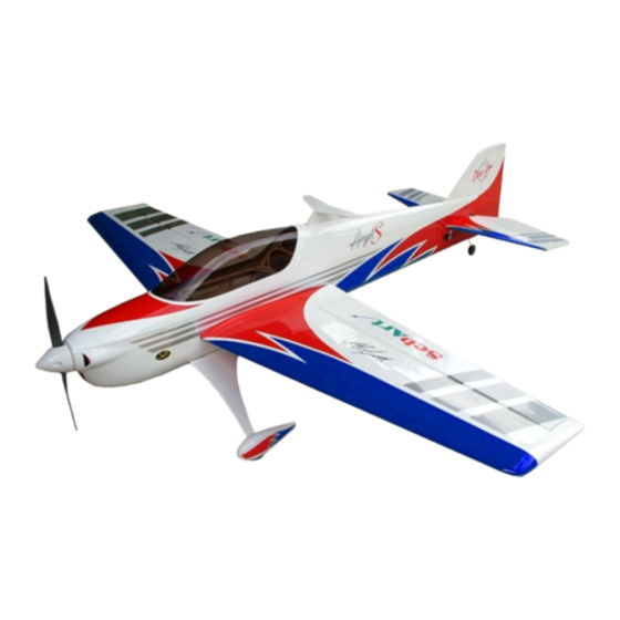
The new F3A-70E , was designed in an extremely lightweight structure,
the all wood airframe, and the new revolutionary Lift Generator on
landing gear give the F3A-70E an impressive thrust- to-weight ratio and
an impressive precision at any airspeed and flight condition.
The F3A-70E can do it all... it is ready for any pattern sequence as for
unbelievable easy torque rolls, slow speed knife-edge and almost
anything else you can dream up are waiting you!
.....without any aerobatic limit when you fantasy to do it !
Specifications
Wing Span:.....................1381 mm (54 in.)
Length:................. ......... 1428 mm (56 in.)
Wing Area:................... 37.5 dm2 (59 sq.in.)
Weight: 3000 g. RTF less battery (77,4 oz)
Radio:.....4-Channel with 4 standard servos
F3A -70E
ASSEMBLY MANUAL
Recommended power set up:
Motor:.... .......... .......... ... Hacker A50-16S
ESC:...... ...... ... ... ...... . X70 SBec-Pro
Battery: Flight Power 3300-6S or 3700-6S
Propeller: ... .... ....... ....... APC 16x10E
1
Advertisement
Table of Contents

Subscribe to Our Youtube Channel
Related Manuals for Sebart F3A-70E


Summary of Contents for Sebart F3A-70E
- Page 1 F3A-70E an impressive thrust- to-weight ratio and an impressive precision at any airspeed and flight condition. The F3A-70E can do it all… it is ready for any pattern sequence as for unbelievable easy torque rolls, slow speed knife-edge and almost anything else you can dream up are waiting you! ..without any aerobatic limit when you fantasy to do it !
-
Page 2: Table Of Contents
Table of contents Table of contents..........................2 Required radio, motor and battery ....................3 Additional required items, tools and adhesives................3 Warning............................3 Before starting assembly ........................ 3 Using the manual........................... 4 Section 1 – ailerons installation...................... 5 Section 2 –... -
Page 3: Required Radio, Motor And Battery
Required radio, motor and battery Radio equipment: Minimum 4-channel radio system 4 digital standard servo, recommended JR PROPO DS9401 or DS8301 1 servo extension 600mm, for elevator servo 2 servo extension 100mm, for aileron’s servos Recommended electric motor for best performance: ... -
Page 4: Using The Manual
Using the manual This manual is divided into sections to help make assembly easier to understand and to provide breaks between each major section. In addition, check boxes have been placed next to each step to keep track of each step completed. -
Page 5: Section 1 - Ailerons Installation
Section 1 – ailerons installation step 1 Trial fit the four aileron hinges, included in the hardware pack, in their place and verify the correct position and alignment of the aileron with the wing panel. step 2 Carefully glue, with some drops of thin CA, each of the four hinges in the aileron. ... -
Page 6: Section 2 - Aileron Servo & Control Horn Installation
step 4 Work the aileron up and down some times to work the hinges and check for proper movement. step 5 Repeat steps 1 through 4 for the remaining wing panel. Section 2 – aileron servo & control horn installation ... - Page 7 step 4 Glue the epoxy horn with medium CA into the aileron,as per picture. step 5 Put the pre-installation servo into the wing panel,as per picture. step6 Install the push and pull rod connecting rod. This four place need to use a needle to remove the cover and fix the plywood with the self-tapping screws.
-
Page 8: Section 3 - Rudder Installation & Tail Wheel Installation
Section 3 – rudder installation & tail wheel installation step 1 Locate the items included in the hardware pack. step 2 Drill in the rudder, 20mm from the bottom, the location for the tail wheel using a 2mm drill bit. With the hobby knife cut a groove of 20mm length into the rudder. - Page 9 step 4 Drill the screw locations for the tail wheel using a 1,5mm drill bit, and install it as per picture. step 5 Insert the three hinges in their appropriate slots and glue them with some drops of thin CA. ...
-
Page 10: Section 4 - Elevator Installation
Section 4 – elevator installation step 1 Insert in the elevator the four hinges into their appropriate slots and verify the correct position and alignment of the elevator with the stabilizer. Than carefully glue the hinges, with some drops of thin CA, in the elevator only. - Page 11 step 4 Glue carefully the hinges in the stabiliser with some drops of thin CA. step 5 Locate the carbon tube in his position and carefully check the alignment of the stabilizer with the fuselage, as per pictures. ...
-
Page 12: Section 5 - Elevator Servo & Control Horn Installation
Section 5 – elevator servo & control horn installation step 1 Locate the following items included in the hardware pack, servo extension 600mm long and servo. This one can use the Hexagonal Ball linkage step 2 Than install the servo hardware (gommets and eyelets) and locate the servo into the fuselage. Before install the servo use a knife to remove the cover... -
Page 13: Section 6 - Rudder Servo & Control Horn Installation
step 4 Glue the epoxy horn with medium CA into the elevator. Than install the hardware and make the final adjustment as per picture. Section 6 – rudder servo & control horn installation step 1 Locate the following items included in the hardware pack, servo extension 600mm long and servo. ... - Page 14 step 3 Glue the fibreglass horn with medium CA into the rudder. step 4 Install the hardware and make the final adjustment as per picture.
-
Page 15: Section 7 - Landing Gear & Wheels Installation
Section 7 – landing gear & wheels installation step 1 Locate the following items included in the hardware pack. step 2 Fix the wheel on the landing gear as the per picture showed. - Page 16 step 3 Locate the landing gear on the fuselage and fix it with the hexagon socket head cap screw included in the hardware pack. step 4 Install wheel pant as per pictures. step 5 Test fit the L.G. Lift Generator and his alignment with the fuselage.
-
Page 17: Section 8 - Electric Motor Installation
step 6 Glue carefully the landing gear fillet with some drops of medium CA, as per picture. step 7 Repeat steps 3 to 6 for the other side of the landing gear. Section 8 – electric motor installation ... - Page 18 step 4 Locate the motor and fix it with the four M4 screws and retaining nuts in the hardware pack. step 2 Locate and fix the ESC and his switch as per picture. step 3 Glue with some drops of medium CA on side of the Velcro strip included in the hardware pack.
-
Page 19: Section 9 - Cowl Installation
Section 9 – cowl installation step 1 Apply a piece of masking tape on the line were you have to make the holes for the cowl fixing screws, than mark the position as per the picture. step 2 Slide the cowling onto the fuselage and install the spinner back plate. -
Page 20: Section 10 - Final Radio Installation
step 4 Fix carefully the prop and the spinner as per picture. Section 10 – final radio installation Install the receiver, two extension 100mm for aileron servos and the battery pack as per the picture. -
Page 21: Wings Installation
Wings installation Locate the wing panels and fix them using the two nylon screws, included in the hardware pack, and a Phillips screwdriver. Decal set application... -
Page 22: Control Throws
Control throws Please, follow carefully the recommended linkage setups for ailerons and elevators. For the AILERON we recommend the following throws: Low rate: 20° up / 20° down Expo: 40% High rate: 40° up / 40° down Expo: 80% For the ELEVATOR we recommend the following throws: Low rate: 20°...
Need help?
Do you have a question about the F3A-70E and is the answer not in the manual?
Questions and answers