Table of Contents
Advertisement
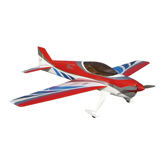
SebArt
The new Wind S 110 ARF was designed by Italy aerobatic pilot,
Sebastiano Silvestri.
This professional ARTF kit is the result of Sebastiano's 20 years
experience in F3A world and his research in best F3A
performances. This innovative design combined with the
extremely lightweight structure, all wood airframe, give the Wind
S 110 ARF an impressive precision and smoothness at any
airspeed and flight condition.
The Wind S 110 ARF can be your best F3A practice plane, or...
if you install the "3D" optional elevator kit, you can let it do all...
precision aerobatics and unbelievable easy harriers, torque rolls,
blenders, waterfalls and almost anything else you can dream up
are waiting you!
Specifications:
Wingspan:..............174 cm
Length:.................180 cm
Wing Area:..............58 dm²
Wind S
ASSEMBLY MANUAL
.....the only aerobatic limit is your fantasy!
professional line
110
Recommended Set Up:
Weight:.........3.200-3.300 g. RTF less motor battery
Radio:........................6-ch with 5 digital servos
Motor: ...Hacker A50-16L + MasterBasic 90-Opto
Prop: ...........................APC 18x10E or 18x12E
Motor battery: ............4350-8S Flight Power 30C
ARF
Advertisement
Table of Contents

Related Manuals for Sebart Wind S 110 ARF


Summary of Contents for Sebart Wind S 110 ARF
- Page 1 S 110 ARF an impressive precision and smoothness at any airspeed and flight condition. The Wind S 110 ARF can be your best F3A practice plane, or… if you install the “3D” optional elevator kit, you can let it do all…...
-
Page 3: Table Of Contents
Table of contents Table of contents.......................……….. 2 Required radio, motor and battery.....................…. 3 Additional required items, tools and adhesives................3 Warning............................3 Before starting assembly ......................… 4 Using the manual........................... 4 Warranty information…......................... 4 Section 1 – ailerons installation…………………………………………........5 Section 2 –... -
Page 4: Required Radio, Motor And Battery
Required radio, motor and battery Radio equipment: • 6-channel radio system • 5 digital servos, with two options: > F3A + 3D……5 JR DS 8401 or DS 8411 > ONLY F3A….3 JR DS 8401 + 2 JR DS 3201 • 2 servo extension 100mm, for aileron’s servos •... -
Page 5: Before Starting Assembly
Remember to take your time and follow the directions. Warranty information SebArt garantees this kit to be free from defects in both material and workmanship at the date of purchase. This warranty does not cover any parts damage by use or modification, and in no case shall SebArt’s liability exceed the original cost of the purchased kit. -
Page 6: Section 1 - Ailerons Installation
Section 1 – ailerons installation step 1 Locate the wing panel and his aileron. Trial fit the four aileron hinges, included in the hardware pack, in their place and verify the correct position and alignment of the aileron with the wing panel. step 2 Carefully glue, with some drops of thin CA, each of the four hinges in the aileron. -
Page 7: Section 2 - Aileron Servo & Control Horn Installation
step 4 Work the aileron up and down some times to work the hinges and check for proper movement. step 5 Repeat steps 1 through 4 for the remaining wing panel. Section 2 – aileron servo & control horn installation step 1 Locate the following items, included in the hardware, plus the long arm and servo (not included). - Page 8 step 2 With the hobby knife open the control horn location. step 3 Place the fibreglass horn into aileron, check for correct alignment and glue it with some drops of medium CA. step 4 Drill the location for the four self-tapping screw using a 1.5mm drill bit and install the servo into the wing panel using a Phillips screwdriver, as per the picture.
- Page 9 step 5 Bring out the servo’s lead. step 6 Install the control horn as per picture. step 7 Repeat steps 1 through 6 for the remaining wing panel.
-
Page 10: Section 3 - Tail Wheel & Rudder Installation
Section 3 – tail wheel & rudder installation step 1 Locate the following items, included in the hardware. step 2 Assemble the tail wheel as follow. - Page 11 step 3 With the hobby knife cut a groove 20mm length into the rudder. Using a 2mm drill bit, carefully drill the hole into rudder, 20mm from the base level, for the tail wheel, as follow. step 4 Locate the tail wheel on rudder and glue it with some drops of medium CA. step 5 Insert the three hinges in their appropriate slots of the rudder, and glue them with some drops of thin CA.
- Page 12 step 6 Carefully locate the rudder and glue the hinges with some drops of thin CA. step 7 Work the rudder right and left some times to work the hinges and check for proper movement. step 8 Using a 1,5mm drill bit, carefully drill the two holes for fixing the tail wheel on the fuselage. Use the two self-tapping screws to install the tail wheel as follow.
-
Page 13: Section 4 - Elevator Installation
Section 4 – elevator installation step 1 Insert in the elevator the three hinges into their appropriate slots and verify the correct position and alignment of the elevator with the stabilizer. step 2 Carefully glue the hinges, with some drops of thin CA, in the elevator only. step 3 Locate the elevator hinges into the stabiliser. -
Page 14: Section 5A - Servo & Control Horn Installation (Only F3A)
Section 5A – servo & control horn installation (ONLY F3A) Note: if you chose the MINI servo installation direct in the stabilizer, you can not use the 3D optional elevators too. If you want to fly both, F3A elevators and 3D optional elevators, on the same model, go direct at “Section 5B”, page 15 of this instruction manual. - Page 15 step 3 Place the fibreglass horn into elevator, check for correct alignment and glue it with some drops of medium CA. step 4 Locate the servo into stabilizer in his location, bringing out the servo’s lead. Drill using a 1,5mm drill bit, and install the four servo’s screws using a Phillips screwdriver. step 5 Install the hardware and make the final adjustment as per picture.
-
Page 16: Section 5B - Servo & Control Horn Installation (F3A + 3D Option)
step 6 Install the elevator on the fuselage, with the two screws and washer included in the hardware pack. step 7 Repeat steps 1 through 6 for the remaining stabilizer. Section 5B – servo & control horn installation (F3A + 3D option) step 1 (LEFT side) Locate the following items, included in the hardware pack and the standard size servo (not included). - Page 17 step 2 With the hobby knife open carefully the servo location in the fuselage, as follow. step 3 Connect and secure, with masking tape, the servo’s extension. Locate the servo and carefully bring forward into fuselage the servo’s lead. Drill, using a 1,5mm drill bit, and install the four servo’s screws using a Phillips screwdriver.
- Page 18 step 5 Install the elevator carbon tube, and using the provided two screws and washer install the stabilizer. step 6 Install the hardware and make the final adjustment as per picture.
- Page 19 step 7 (RIGHT side) Locate the following items, included in the hardware pack and the standard size servo (not included). Install the servo hardware (gommets and eyelets) included with the servo. step 8 Repeat steps 2 through 5 for the remaining stabilizer. step 9 Install the hardware and make the final adjustment as per picture.
-
Page 20: Section 6 - 3D Elevator & Control Horn Installation (Optional)
Section 6 - 3D elevator & control horn installation (OPTIONAL) NOTE: As spare part, you can buy the “OPTIONAL 3D ELEVATOR for Wind S110”. step 1 When you like to install the 3D elevator remove the F3A elevators with control horns and servo arms and the carbon tube, as follow. - Page 21 step 3 Prepare the hinges for the application, using one small drop of sinthetic oil in their center of movement. step 4 Use good quality 5 minutes epoxy to glue the hinges in the elevator, and remember to check the correct sense of work for every hinge.
- Page 22 step 6 Work the elevator up and down some times to work the hinges and check for proper movement. step 7 Repeat steps 2 through 6 for the remaining stabilizer. step 8 (LEFT side) Locate the following items, included in the hardware pack of the “OPTIONAL 3D ELEVATOR”. step 8 With the hobby knife remove the cover in the control horn location.
- Page 23 step 9 Locate the new longer elevator carbon tube (310mm), included in the hardware pack of the “OPTIONAL 3D ELEVATOR”, and using the provided two screws and washer install the stabilizer. step 10 Install the hardware and make the final adjustment as per picture.
- Page 24 step 11 (RIGHT side) Locate the following items, included in the hardware pack of the “OPTIONAL 3D ELEVATOR”. step 12 Repeat steps 8 through 9 for the remaining stabilizer. step 13 Install the hardware and make the final adjustment as per picture.
-
Page 25: Section 7 - Rudder Servo Installation
step 14 When you like to install again the F3A elevators, remove the 3D elevator with control horns and servo arms and the carbon tube, as follow. Section 7 – rudder servo installation step 1 Locate the following items, included in the hardware pack and the servo (not included). Install the servo hardware (gommets and eyelets). - Page 26 step 2 Drill the location for the four self-tapping screw using a 1.5mm drill bit and install the servo as per the picture. step 3 With the hobby knife remove the cover on both rudder’s side in the control horn location. step 4 Place the fibreglass control horn in the rudder, check for correct alignment and glue it with some drops of medium CA.
- Page 27 step 5 Prepare the rudder cable as follow. step 6 Install the rudder cable as follow. step 7 Repeat steps 5 through 6 for the opposite side of the fuselage.
-
Page 28: Section 8 - Landing Gear & Wheels Installation
step 8 Attach a heavy-duty servo arm to the rudder servo, attach the uniballs at the servo arm and adjust the linkages, in order to have rudder and servo in central position. Section 8 – landing gear & wheels installation step 1 Locate all the necessary items. - Page 29 step 2 Using screws and washers, install the landing gear as follow. step 3 Install the axle, wheel as follow. step 4 Install wheel as follow.
- Page 30 step 5 Prepare the wheel pant and install it as follow. step 6 Hold the wheel pant parallel to the fuselage and drill the location for the wheel pant screw using a 1,5mm drill bit. Attach the wheel pant to the landing gear using a 2mm short self-tapping screw. step 7 With the hobby knife open the slot on the fuselage and test fit the landing gear fillet and his alignment.
-
Page 31: Section 9 - Electric Motor Installation
step 8 Once satisfied with the fit, glue the fillet on the landing gear using medium CA. Use the glue carefully avoid over runs on other areas. step 9 Repeat steps 2 through 8 for the opposite landing gear side. Section 9 –... - Page 32 step 2 Locate on the back motor’s axis the bearing included in the hardware pack. step 3 Install the motor into fuselage as follow. step 4 Locate the plywood frame as motor support, and install it with self-tapping screws included in the hardware pack.
- Page 33 step 5 Apply the velkro on the ESC location. step 6 Install the ESC as follow. step 7 Fix carefully the prop and spinner.
-
Page 34: Section 10 - 3D Fuselage's & Wing's Fins Installation (Optional Installation)
Section 10 – 3D fuselage’s & wing’s Fins installation (optional installation) The 3D fuselage’s & wing’s Fins are included in the box, and they are an optional installation. If you like, install them as follow. step 1 Locate the following item included in the box. step 2 Glue with medium CA the two parts of the fuselage’s fin. - Page 35 step 3 With the hobby knife open the two slots on top fuselage and carefully glue the fin with medium CA. step 4 With the hobby knife open the slot on the wing’s leading edge and test fit the fin on wing panel. step 5 Glue carefully the fin with medium CA.
-
Page 36: Section 11 - Final Radio Installation
Section 11 – final radio installation For best performance and light weight, we recommend you to install as receiver & servos power system the following item (not included): • Power Box System “DIGI Switch” (ONLY for F3A set up) • Power Box System “SENSOR” Switch (for F3A &... - Page 37 step 2 Locate and install the switch with a Phillips screwdriver as follow. step 3 Locate RX-battery and receiver as follow.
-
Page 38: Canopy Installation
Canopy installation Install the canopy with the two 3mm screws and washers included in the hardware pack. Wings installation Locate the wing panels and fix them using the two 4mm screws, included in the hardware pack, and a Phillips screwdriver. -
Page 39: Control Throws
Control throws We recommend the use of a computer radio, that will allow you to do quite a bit of fine-tuning of the feel of the Wind S 110, which will make aerobatics even easier. Please, follow carefully the recommended linkage setups: For the AILERON we recommend the following throws: Low rate: 20°... -
Page 40: Rates And Expos
Be sure that your Flight Power batteries are fully charged, as per the instructions included with your batteries and that your radio is fully charged as per its instructions. Finally... have a nice flight! SebArt di Sebastiano Silvestri Via Trento 69/3 38017 Mezzolombardo (TN) – Italy www.sebart.it...
Need help?
Do you have a question about the Wind S 110 ARF and is the answer not in the manual?
Questions and answers