Table of Contents
Advertisement
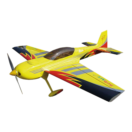
SebArt
The new KatanaS 120 ARF was designed by Italy aerobatic pilot,
Sebastiano Silvestri and the design is based on of his successful
and famous KatanaS Tournament Of Champion's airplane.
This professional ARTF kit is the result of Sebastiano's long
research in 3D performance. This combined with an extremely
lightweight structure, the all wood airframe and the big control
surfaces give the KatanaS 120E an impressive thrust-to-weight
ratio and crisp control authority at any airspeed and flight
condition.
The KatanaS 120E can do it all...unbelievable easy harriers,
torque rolls, blenders, waterfalls and almost anything else you can
dream up are waiting you!
Specifications:
Wingspan:.............187 cm (73,61 in)
Length:................186 cm (73,22 in)
Wing Area:.............78 dm² (121 sq.in)
KatanaS
ASSEMBLY MANUAL
.....the only aerobatic limit is your fantasy!
professional line
120
Recommended Set Up:
Weight:....3.900 - 4.100 g. RTF less motor battery
Radio:.....6-ch with 5 digital servos metal gear
Motor: ...Hacker A60-22S + MasterBasic 90-Opto
Engine: ...2 or 4 cycle 1.20 - 1.80
ARF
Advertisement
Table of Contents

Related Manuals for Sebart KatanaS 120 ARF


Summary of Contents for Sebart KatanaS 120 ARF
- Page 1 KatanaS ASSEMBLY MANUAL The new KatanaS 120 ARF was designed by Italy aerobatic pilot, Sebastiano Silvestri and the design is based on of his successful and famous KatanaS Tournament Of Champion’s airplane. This professional ARTF kit is the result of Sebastiano’s long research in 3D performance.
-
Page 2: Table Of Contents
Table of contents Table of contents.......................……….. 2 Required radio, motor and battery.....................…. 3 Additional required items, tools and adhesives................3 Warning............................3 Before starting assembly ......................… 4 Using the manual........................... 4 Warranty information…......................... 4 Section 1 – wing fillet installation…....................5 Section 2 –... -
Page 3: Required Radio, Motor And Battery
Required radio, motor and battery Radio equipment: • Minimum 5-channel radio system • 5 digital servos metal gear, recommended JR PROPO DS 8411 • 2 servo extension 300mm, for elevator’s servos • 4 servo extension 100mm, for aileron’s servos Recommended electric motor for best performance: •... -
Page 4: Before Starting Assembly
Remember to take your time and follow the directions. Warranty information SebArt garantees this kit to be free from defects in both material and workmanship at the date of purchase. This warranty does not cover any parts damage by use or modification, and in no case shall SebArt’s liability exceed the original cost of the purchased kit. -
Page 5: Section 1 - Wing Fillet Installation
Section 1 – wing fillet installation step 1 On the fuselage, with an hobby knife open carefully in the covering the holes for wing panel three pins, wing tube, wing retainer and servo lead. step 2 Locate the corresponding wing fillet to the wing. step 3 Locate the wing tube in the fuselage, and carefully slide the wing panel. - Page 6 step 4 Once satisfied with the fit, glue the wing fillet to the wing panel using medium CA. Use the glue carefully avoid over runs onto the area to be covered with the material. step 5 Use the covering iron carefully, at a medium temperature, to glue the cover material down around the area of the fillet.
-
Page 7: Section 2 - Ailerons Installation
Section 2 – ailerons installation step 1 Locate the five aileron pin-hinges included in the hardware and trial fit in their place and verify the correct position and alignment of the aileron with the wing panel. step 2 Before to glue the hinges, carefully put few drops of oil in the hinge of the pin-hinges. Locate and glue the five hinges with 5 minutes epoxy, verifying their correct alignment. -
Page 8: Section 3 - Aileron Servo & Control Horn Installation
step 4 Work the aileron up and down some times to work the hinges and check for proper movement. step 5 Repeat steps 1 through 4 for the remaining wing panel. Section 3 – aileron servo & control horn installation step 1 Locate the following items, included in the hardware, plus the long arm and servo (not included). - Page 9 step 2 With the hobby knife open the servo bay and the control horn location. step 3 Place the fibreglass control horn into aileron, check for correct alignment and glue it with some drops of medium CA. step 4 Drill the location for the four self-tapping screw using a 1.5mm drill bit and install the servo into the wing panel as per the picture.
- Page 10 step 5 Bring out the servo lead. step 6 Install the control horn as per picture. step 7 Repeat steps 1 through 6 for the remaining wing panel.
-
Page 11: Section 4 - Elevator Installation
Section 4 – elevator installation step 1 Locate the following items, included in the hardware. step 2 Cut only one (1) of the three hinge as follow. step 3 Place the three hinges in their holes, and verify the correct position and alignment of the elevator with the stabilizer panel. - Page 12 step 4 Prepare the hinges for the application, using one small drop of sinthetic oil in their center of movement, like for the ailerons application. step 5 Use good quality 5 minutes epoxy to glue the hinges in the elevator, and remember to check the correct sense of work for every hinge.
- Page 13 step 7 Work the elevator up and down some times to work the hinges and check for proper movement. step 8 With the hobby knife remove the cover in the control horn location. step 9 Place the fibreglass control horn into elevator, check for correct alignment and glue it with some drops of medium CA.
-
Page 14: Section 5 - Elevator Servo Installation
Section 5 – elevator servo installation step 1 Install the servo hardware (gommets and eyelets) included with the servo. Locate the following items, included in the hardware, plus the long arm and servo (not included). step 2 With the hobby knife open the stabiliser location on fuselage and the elevator servo bay. - Page 15 step 3 Drill the location for the four self-tapping screw using a 1.5mm drill bit and install the servo into the wing panel as per the picture. step 4 Locate the stabilizer carbon tube into fuselage and carefully slide the stabilizer on it too. step 5 Fix the stabilizer on the fuselage with the provided 3mm screws and washers.
-
Page 16: Section 6 - Tail Wheel & Rudder Installation
step 6 Install the control horn as per picture. step 7 Remove the stabilizer, and repeat steps 1 through 6 for the opposite side of the fuselage. Section 6 – tail wheel & rudder installation step 1 Locate the following items, included in the hardware. - Page 17 step 2 Using a 2mm drill bit, carefully drill the hole into rudder, 25mm from the base level, for the tail wheel. With the hobby knife cut a groove 25mm length into the rudder as follow. step 3 Assemble the tail wheel as follow. step 4 Locate the tail wheel on rudder and glue it with some drops of medium CA.
- Page 18 step 5 Prepare the hinges for the application, using one small drop of sinthetic oil in their center of movement. step 6 Use 5 minutes epoxy to glue the hinges in the rudder, remember to check the correct sense of work for every hinge.
- Page 19 step 8 Work the rudder right and left some times to work the hinges and check for proper movement. step 9 Using a 1,5mm drill bit, carefully drill the two holes for fixing the tail wheel on the fuselage. step 10 Use the two self-tapping screws to fix the tail wheel as follow.
-
Page 20: Section 7 - Rudder Servo Installation
Section 7 – rudder servo installation step 1 Install the servo hardware (gommets and eyelets) included with the servo and locate the following items, included in the hardware. step 2 Drill the location for the four self-tapping screw using a 1.5mm drill bit and install the servo as per the picture. - Page 21 step 3 With the hobby knife remove the cover in the control horn location. step 4 Place the fibreglass control horn in the rudder, check for correct alignment and glue it with some drops of medium CA.
- Page 22 step 5 Prepare the rudder cable as follow. step 6 Install the rudder cable as follow. step 7 Repeat steps 3 through 6 for the opposite side of the fuselage.
-
Page 23: Section 8 - Landing Gear & Wheel Installation
step 8 Attach a heavy-duty servo arm to the rudder servo, attach the uniballs at the servo arm and adjust the linkages, in order to have rudder and servo in central position. Section 8 – landing gear & wheels installation step 1 Locate all the necessary items. - Page 24 step 2 Install the landing gear as follow. step 3 Install the axle, wheel as follow. step 4 Install wheel and wheel pant as follow.
- Page 25 step 5 Hold the wheel pant parallel to the fuselage and drill the location for the wheel pant screw using a 1,5mm drill bit. Attach the wheel pant to the landing gear using a 2mm short self-tapping screw. step 6 Test fit the landing gear fillet and his alignment.
-
Page 26: Section 9 - Electric Motor & Cowl Installation
Section 9 – electric motor & cowl installation We recommend to fly HACKER motor, you need the following item (not included): • Hacker A60-22S + MasterBasic90-Opto controller + APC 20 x 10 E • Hacker motor mount for A60 series step 1 Assemble the motor mount as follow. - Page 27 step 2 Install the motor on the mount as follow. step 3 Drill the location of the blind nuts where it is marked on the firewall and install the 4 mm blind nuts included in the hardware pack. Check the right length of the mount and install it on the fuselage as follow.
- Page 28 step 4 Install the ESC as follow. On bottom of fuselage, with the hobby knife remove the cover opening the holes for cooling. step 5 Apply a piece of masking tape on the line were you have to make the holes for the cowl fixing screws, and mark the position as per the picture.
- Page 29 step 6 Slide the cowling onto the fuselage and install the spinner back plate. Position and hold the cowl so there is 3mm gap between the back plate and the cowl. Then apply another piece of masking tape on the same line of the one applied before. step 7 Drill the location for the four self-tapping screws using a 1.5mm drill bit.
-
Page 30: Section 10 - Glow Engine & Cowl Installation
Section 10 – Glow engine installation We recommend to use the OS 1.20 FX two-cycle engine or 1.20-1.50 four-cycle engine. step 1 Locate all the parts of the glow conversion kit included in the kit. step 2 Install and glue all the parts with medium CA as follow. - Page 32 step 3 Locate the engine and the mount parts included in the hardware pack. step 4 Install the engine as follow.
- Page 33 step 5 Locate the throttle servo, the servo support parts and tank parts included in the hardware pack.
- Page 34 step 6 Install the throttle servo as follow.
- Page 35 step 7 Assemble and locate the tank as follow.
- Page 36 step 8 Install the cowl and the engine silencer as follow.
-
Page 39: Section 11 - Final Radio Installation
Section 11 – final radio installation For best performance and light weight, we recommend you to install as receiver & servos power system the following item (not included): • Power Box System “SENSOR” Switch • Power Box System 1500 li-po battery or Flight Power 1250-2S EVO-RX li-po battery... -
Page 40: Section 12 - Hatch & Cockpit Installation
Section 12 – hatch & cockpit installation For best look, we recommend you to install the optional parts Pilot figure and Panel instrument (not included): step 1 Locate the following items. - Page 41 step 2 Assemble panel instrument and pilot figure as per their included manual. step 3 Locate the depron base in the canopy and glue the panel instrument and pilot figure with 5 minutes epoxy, as per picture. step 4 Locate the canopy on fuselage and place the 3mm screws with washers to fix it, as per picture.
-
Page 42: Wing Installation
Wings installation Locate the wing panels and fix them using the two 4mm screws, included in the hardware pack, and a Phillips screwdriver. Control throws We recommend the use of a computer radio, that will allow you to do quite a bit of fine-tuning of the feel of the Katana, which will make aerobatics even easier. -
Page 43: Rates And Expos
Be sure that your Flight Power batteries are fully charged, as per the instructions included with your batteries and that your radio is fully charged as per its instructions. Finally... have a nice flight! SebArt di Sebastiano Silvestri Via Trento 69/3 38017 Mezzolombardo (TN) – Italy www.sebart.it...
Need help?
Do you have a question about the KatanaS 120 ARF and is the answer not in the manual?
Questions and answers