Table of Contents
Advertisement
SebArt
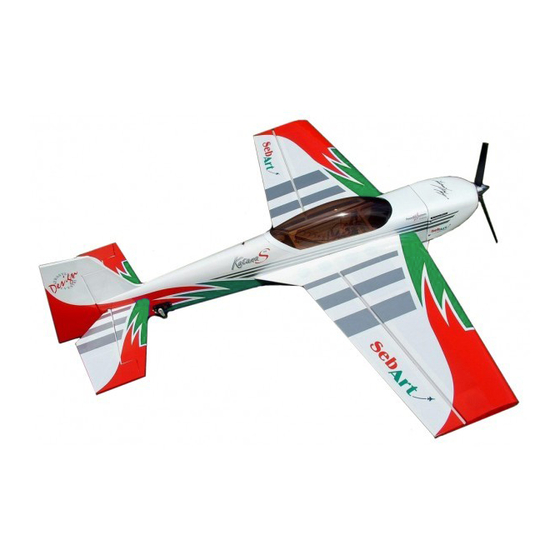
The new KatanaS 30E ARF was designed by Italy aerobatic pilot,
Sebastiano Silvestri and the design is based on of his successful
and famous KatanaS Tournament Of Champion's airplane.
This professional ARTF kit is the result of Sebastiano's long
research in 3D performance. This combined with an extremely
lightweight structure, the all wood airframe and the big control
surfaces give the KatanaS 30E an impressive thrust-to-weight
ratio and crisp control authority at any airspeed and flight
condition....That for this small class of airplane is revolutionary!
The KatanaS 30E can do it all...unbelievable easy harriers, torque
rolls, blenders, waterfalls and almost anything else you can dream
up are waiting you!
.....the only aerobatic limit is your fantasy!
Specifications
Wingspan:.............125 cm (49,21 in)
Length:................ 125 cm (49,21 in)
Wing Area:............36,5 dm² (56,57 sq.in)
KatanaS
ARF
ASSEMBLY MANUAL
professional line
30E
Weight:.....1.2 kg (2,64 lb) with 2.150 LiPo F.P.
Radio:......minimum 4-channel with 4 servos 12g
Engines:....Hacker A30-14L + X40 controller
Advertisement
Table of Contents

Related Manuals for Sebart KatanaS 30E


Summary of Contents for Sebart KatanaS 30E
- Page 1 KatanaS ASSEMBLY MANUAL The new KatanaS 30E ARF was designed by Italy aerobatic pilot, Sebastiano Silvestri and the design is based on of his successful and famous KatanaS Tournament Of Champion’s airplane. This professional ARTF kit is the result of Sebastiano’s long research in 3D performance.
-
Page 2: Table Of Contents
Table of contents Table of contents.......................……….. 2 Required radio, motor and battery.....................…. 3 Additional required items, tools and adhesives................3 Warning............................3 Before starting assembly ......................… 3 Using the manual........................... 3 Warranty information…......................... 4 Section 1 – wing fillet installation…....................5 Section 2 –... -
Page 3: Required Radio, Motor And Battery
Before starting assembly Before starting the assebly of your KatanaS 30E, remove each part from its bag and protection for a prior inspection. Closely inspect the fuselage, wing panels, rudder, and stabilizer for damage. If you find any damage or missing parts, contact the place of purchase. -
Page 4: Using The Manual
Rember to take your time and follow the directions. Warranty information SebArt garantees this kit to be free from defects in both material and workmanship at the date of purchase. This warranty does not cover any parts damage by use or modification, and in no case shall SebArt’s liability exceed the original cost of the purchased kit. -
Page 5: Section 1 - Wing Fillet Installation
Section 1 – wing fillet installation step 1 Locate the corresponding wing fillet to the wing. Test fit the fillet and his alignment with the wing panel. Once satisfied with the fit, glue the wing fillet to the wing panel using medium CA. Use the glue carefully avoid over runs onto the area to be covered with the material. -
Page 6: Section 2 - Ailerons Installation
Section 2 – ailerons installation step 1 Trial fit the four aileron hinges, included in the hardware pack, in their place and verify the correct position and alignment of the aileron with the wing panel. step 2 Carefully glue, with some drops of thin CA, each of the four hinges in the aileron. -
Page 7: Section 3 - Aileron Servo & Control Horn Installation
step 3 Carefully glue, with some drops of thin CA, each of the four hinges into the wing panel. step 4 Work the aileron up and down some times to work the hinges and check for proper movement. step 5 Repeat steps 1 through 4 for the remaining wing panel. - Page 8 step 2 Locate the following items, one servo extension 100mm long and the servo. step 3 Install the servo hardware (gommets and eyelets) included with the servo. Install the servo and control horn into the wing panel as per the picture. step 4 Repeat steps 1 through 3 for the remaining wing panel.
-
Page 9: Section 4 - Rudder Installation
Section 4 – rudder installation step 1 With the hobby knife open the bay for the servos and the stabiliser on both sides of the the fuselage. Than place the rudder in his place into the fuselage, check for a correct alignment and than glue it with some drops of thin CA. -
Page 10: Section 5 - Elevator Installation
Section 5 – elevator installation step 1 Insert the four hinges into there appropriate slots in the elevator and verify the correct position and alignment of the elevator with the stabilizer. Then carefully glue the hinges, with some drops of thin CA, in the elevator only. step 2 Insert carefully the elevator through the fuselage then insert the stabiliser into fuselage space. - Page 11 step 4 Locate the carbon tube in his position and check the alignment with the stabilizer. step 5 Carefully place the hinges in their place, and glue the hinges with some drops of thin CA. step 6 Once satisfied with the alignment, glue with some drops of thin CA the stabilizer at the fuselage.
-
Page 12: Section 6 - Tail Wheel Installation
Section 6 – tail wheel installation step 1 Locate the items included in the hardware pack as follow. step 2 With the hobby knife cut a groove of 20mm length into the rudder. step 3 Install the tail wheel and apply some drops of thin CA, as per picture. -
Page 13: Section 7 - Elevator / Rudder Servo & Control Horn Installation
Section 7 – elevator / rudder servo & control horn installation step 1 Locate the following , servo extension 300mm long and the servo. Install the servo hardware (gommets and eyelets) included with the servo. step 2 Install the elevator servo and control horn into the fuselage as per picture. step 3 Install the rudder servo and control horn into the fuselage as per picture. -
Page 14: Section 8 - Landing Gear & Wheels Installation
Section 8 – landing gear & wheels installation step 1 Locate the landing gear on the fuselage and fix with the two screws included in the hardware pack. step 2 Locate all the necessary items for installing wheel and wheel pants. Than install all the items as per pictures and fix the wheel pant with some drops of thin CA at the landing gear. -
Page 15: Section 9 - Electric Motor Installation
Section 9 – electric motor installation We recommend to use HACKER motor, and you need one of this two options: • Hacker A30-12L + X40 controller + APC 13 x 6.5 E • Hacker A30-14L + X40 controller + APC 14 x 7 E step 1 Open the hole in the motor mounting plate to clear the C-clip on the motor, using a tapered reamer to remove enough material to allow the C-clip to clear the surrounding wood and rotate freely. -
Page 16: Section 10 - Cowl Installation
step 3 Cut and locate the two air plastic air scoops and glue them with thin CA as per picture. step 4 Locate the motor and fix it with the four screws included in the motor hardware pack, then fix the controller in the area shown in the picture. - Page 17 step 2 Slide the cowling onto the fuselage and install the spinner back plate. Position and hold the cowl so there is 2mm gap between the back plate and the cowl. Then apply another piece of masking tape on the same line of the one applied before. Drill the location for the four self-tapping screw using a 1.5mm drill bit.
-
Page 18: Section 11 - Final Radio Installation
Section 11 – final radio installation Section 12 – wings installation Control throws Please, follow carefully the recommended linkage setups for ailerons and elevators. For the AILERON we recommand the following throws: Low rate: 20° up / 20° down Expo: 40% 3D rate: 45°... -
Page 19: Rates And Expos
Finally... Finally... Finally... Finally... ha ha ha have a nice flight! ve a nice flight! ve a nice flight! ve a nice flight! SebArt di Sebastiano Silvestri Via Roma 83/85 38017 Mezzolombardo (TN) – Italy www.sebart.it...
Need help?
Do you have a question about the KatanaS 30E and is the answer not in the manual?
Questions and answers