Table of Contents
Advertisement
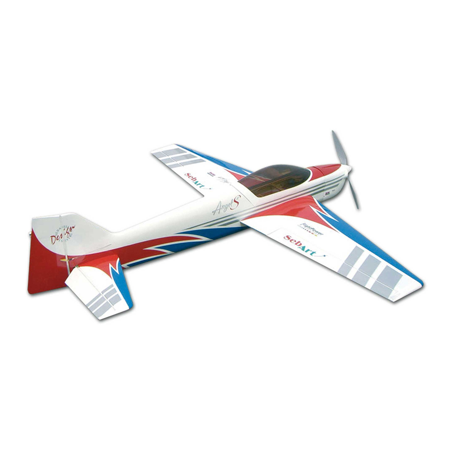
SebArt
The new AngelS
Italian Champion Sebastiano Silvestri, it is the replica of his 2
meter size F3A competition airplane, 3
Championships in Swizerland 2006.
This professional ARTF kit is the result of Sebastiano's long
research and experience in F3A world. This combined with an
extremely lightweight structure, the all wood airframe, and the
new revolutionary Lift Generator on landing gear give the
AngelS
EVO 50E
impressive precision at any airspeed and flight condition.
The AngelS
sequence as for unbelievable easy torque rolls, slow speed
knifedge and almost anything else you can dream up are waiting
you!
.....the only aerobatic limit is your fantasy!
Specifications
Wing Span:.....................
Length:..........................
Wing Area:...................
Weight:.....
2.200 g. RTF less battery (77,4 oz)
Radio:.....4-Channel with 4 standard servos
AngelS
ASSEMBLY MANUAL
ARF, was designed by the 10 times F3A
EVO 50E
an impressive thrust-to-weight ratio and an
can do it all... it is ready for any pattern
EVO 50E
158 cm (62,6 in.)
165 cm (65,4 in.)
45,8 dm2 (71 sq.in.)
professional line
EVO 50E
ARF
Recommended power set up:
Motor:...........................
ESC:.........................
Battery:
Flight Power 3300-6S or 3700-6S
Propeller: .....................
rd
at the European
Hacker A50-16S
X70 SBec-Pro
APC 16x10E
Advertisement
Table of Contents

Related Manuals for Sebart AngelS EVO 50E


Summary of Contents for Sebart AngelS EVO 50E
- Page 1 SebArt professional line AngelS EVO 50E ASSEMBLY MANUAL The new AngelS ARF, was designed by the 10 times F3A EVO 50E Italian Champion Sebastiano Silvestri, it is the replica of his 2 meter size F3A competition airplane, 3 at the European Championships in Swizerland 2006.
-
Page 2: Table Of Contents
Table of contents Table of contents.......................……….. 2 Required radio, motor and battery.....................…. 3 Additional required items, tools and adhesives................3 Warning............................3 Before starting assembly ......................… 3 Using the manual........................... 4 Warranty information…......................... 4 Section 1 – ailerons installation...................... 5 Section 2 –... -
Page 3: Required Radio, Motor And Battery
Required radio, motor and battery Radio equipment: • Minimum 4-channel radio system • 4 digital standard servo, recommended JR PROPO DS9401 or DS8301 • 1 servo extension 600mm, for elevator servo • 2 servo extension 100mm, for aileron’s servos Recommended electric motor for best performance: •... -
Page 4: Using The Manual
Rember to take your time and follow the directions. Warranty information SebArt garantees this kit to be free from defects in both material and workmanship at the date of purchase. This warranty does not cover any parts damage by use or modification, and in no case shall SebArt’s liability exceed the original cost of the purchased kit. -
Page 5: Section 1 - Ailerons Installation
Section 1 – ailerons installation step 1 Trial fit the four aileron hinges, included in the hardware pack, in their place and verify the correct position and alignment of the aileron with the wing panel. step 2 Carefully glue, with some drops of thin CA, each of the four hinges in the aileron. step 3 Locate the aileron and carefully glue, with some drops of thin CA, the hinges into the wing panel. -
Page 6: Section 2 - Aileron Servo & Control Horn Installation
step 4 Work the aileron up and down some times to work the hinges and check for proper movement. step 5 Repeat steps 1 through 4 for the remaining wing panel. Section 2 – aileron servo & control horn installation step 1 Locate the following items included in the hardware pack and the servo. - Page 7 step 3 Drill using a 1,5mm drill bit, and install the servo into the wing panel using a Phillips screwdriver. step 4 Glue the fibreglass horn with medium CA into the aileron. step 5 Install the hardware and make the final adjustment as per pictures. step 6 Repeat steps 1 through 5 for the remaining wing panel.
-
Page 8: Section 3 - Rudder Installation & Tail Wheel Installation
Section 3 – rudder installation & tail wheel installation step 1 Locate the items included in the hardware pack. step 2 Drill in the rudder, 20mm from the bottom, the location for the tail wheel using a 2mm drill bit. With the hobby knife cut a groove of 20mm length into the rudder. - Page 9 step 4 Drill the screw locations for the tail wheel using a 1,5mm drill bit, and install it as per picture. step 5 Insert the three hinges in their appropriate slots and glue them with some drops of thin CA. step 6 Carefully put some drops of medium CA into the 2 mm hole into the rudder.
-
Page 10: Section 4 - Elevator Installation
Section 4 – elevator installation step 1 Insert in the elevator the four hinges into their appropriate slots and verify the correct position and alignment of the elevator with the stabilizer. Than carefully glue the hinges, with some drops of thin CA, in the elevator only. - Page 11 step 4 Glue carefully the hinges in the stabiliser with some drops of thin CA. step 5 Locate the carbon tube in his position and carefully check the alignment of the stabilizer with the fuselage, as per pictures. step 6 Once satisfied with the alignment, glue carefully with thin CA the stabilizer at the fuselage.
-
Page 12: Section 5 - Elevator Servo & Control Horn Installation
Section 5 – elevator servo & control horn installation step 1 Locate the following items included in the hardware pack, servo extension 600mm long and servo. step 2 Than install the servo hardware (gommets and eyelets) and locate the servo into the fuselage. step 3 Drill using a 1,5mm drill bit, and install the servo into the fuselage using a Phillips screwdriver. -
Page 13: Section 6 - Rudder Servo & Control Horn Installation
step 4 Glue the fibreglass horn with medium CA into the elevator. Than install the hardware and make the final adjustment as per picture. Section 6 – rudder servo & control horn installation step 1 Locate the following items included in the hardware pack, servo extension 600mm long and servo. step 2 Than install the servo hardware (gommets and eyelets), drill using a 1,5mm drill bit, and install the servo into the fuselage using a Phillips screwdriver. - Page 14 step 3 Glue the fibreglass horn with medium CA into the rudder. step 4 Install the hardware and make the final adjustment as per picture.
-
Page 15: Section 7 - Landing Gear & Wheels Installation
Section 7 – landing gear & wheels installation step 1 Locate the following items included in the hardware pack. step 2 Locate the landing gear on the fuselage and fix it with the screws included in the hardware pack. step 3 Sand with the sanding paper the inside of the wheel pant;... - Page 16 step 4 Install wheel and wheel pant as per pictures. step 5 Drill the location for the wheel pant fixing screw using a 1,5mm drill bit and than fix the wheel pant with the screw included in the hardware pack. step 6 Test fit the L.G.
-
Page 17: Section 8 - Electric Motor Installation
step 7 Glue carefully the landing gear fillet with some drops of medium CA, as per picture. step 8 Repeat steps 3 to 7 for the other side of the landing gear. Section 8 – electric motor installation For best performance, we recommend to use HACKER motor. step 1 Locate the motor and fix it with the four screws included in the motor hardware pack. - Page 18 step 2 Locate and fix the ESC and his switch as per picture. step 3 Glue with some drops of medium CA on side of the Velcro strip included in the hardware pack. step 4 With the hobby knife open the cooling holes in the fuselage as per picture.
-
Page 19: Section 9 - Cowl Installation
Section 9 – cowl installation step 1 Apply a piece of masking tape on the line were you have to make the holes for the cowl fixing screws, than mark the position as per the picture. step 2 Slide the cowling onto the fuselage and install the spinner back plate. Then apply another piece of masking tape on the same line of the one applied before. -
Page 20: Section 10 - Final Radio Installation
step 4 Fix carefully the prop and the spinner as per picture. Section 10 – final radio installation Install the receiver, two extension 100mm for aileron servos and the battery pack as per the picture. -
Page 21: Wings Installation
Wings installation Locate the wing panels and fix them using the two nylon screws, included in the hardware pack, and a Phillips screwdriver. Decal set application... -
Page 22: Control Throws
Control throws Please, follow carefully the recommended linkage setups for ailerons and elevators. For the AILERON we recommend the following throws: Low rate: 20° up / 20° down Expo: 40% High rate: 40° up / 40° down Expo: 80% For the ELEVATOR we recommend the following throws: Low rate: 20°... - Page 23 Finally... Finally... Finally... Finally... have a nice flight! have a nice flight! have a nice flight! have a nice flight! SebArt di Sebastiano Silvestri Via Roma 83/85 38017 Mezzolombardo (TN) – Italy www.sebart.it...
Need help?
Do you have a question about the AngelS EVO 50E and is the answer not in the manual?
Questions and answers