Finn HydroSeeder T120 Operator Instructions And Parts Manual
Hide thumbs
Also See for HydroSeeder T120:
- Practical service manual for the parts professional (51 pages) ,
- Parts and operator's manual (79 pages) ,
- Technical bulletin (6 pages)
Table of Contents
Advertisement
Operator Instructions and Parts Manual
T120 CE OO1231
9281 LeSaint Drive • Fairfield, Ohio 45014
Phone (513) 874-2818 • Fax (513) 874-2914
Sales: 1-800-543-7166
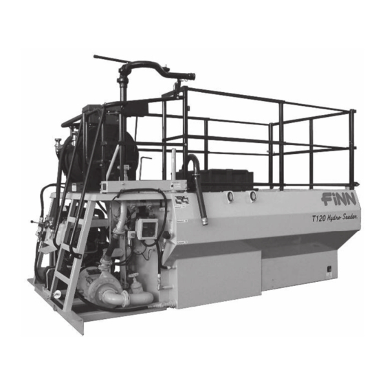
T120 HydroSeeder
CE-Compliant
Model OO
Serial No. _____________
Activate
Activate
Your Warranty
Your Warranty
By Registering
By Registering
TODAY!!!
TODAY!!!
®
Advertisement
Table of Contents

Subscribe to Our Youtube Channel
Related Manuals for Finn HydroSeeder T120


Summary of Contents for Finn HydroSeeder T120
- Page 1 Activate Activate Your Warranty Your Warranty By Registering By Registering TODAY!!! TODAY!!! 9281 LeSaint Drive • Fairfield, Ohio 45014 Phone (513) 874-2818 • Fax (513) 874-2914 Sales: 1-800-543-7166 ® T120 HydroSeeder CE-Compliant Operator Instructions and Parts Manual Model OO Serial No. _____________ T120 CE OO1231...
- Page 2 FOR OFFICE USE ONLY DATE UPDATE DESCRIPTION CODE 12/31/22 Initial release: new structural assembly OO1231...
- Page 3 Labor hours must coincide with the published “Labor Schedule” or estimate approved by the Finn Warranty Administrator. Once work is done, a Finn Warranty Claim Form must be Þ lled out and emailed along with any related receipts or invoices to the Warranty Administrator. We ask that this is done ASAP after work is completed.
-
Page 5: Table Of Contents
Emergency Stop ........... . 34 ® HydroSeeder is a registered trademark of the FINN Corporation... - Page 6 INDEX (CONTINUED) Starting Procedure ..........35 Area Coverage –...
-
Page 7: Safety First
SAFETY FIRST With any piece of equipment, new or used, the most important part of its operation is SAFETY! FINN Corporation encourages you and your employees to familiarize yourselves with your new equipment and stresses safe operation. The first five pages of this manual are a summary of the main safety aspects associated with this unit. -
Page 8: Hydroseeder ® Safety Summary Section
® The FINN HydroSeeder is designed to mix and apply water, seed, fertilizer, agricultural lime, and hydraulic mulch to the prepared seedbed. The resultant slurry from mixing one or more of the above materials may react, causing harmful or deadly gasses within the tank. - Page 9 4. During application through a hose, high pressure II. MACHINE OPERATION (Continued) can be exerted at the end of the hose. Hose-holding personnel must establish good footing. The operator 6. Operator(s) of equipment should should apply gradual pressure to the hose only after never ride on the machine at hose-holding personnel are firmly positioned and speeds of greater than 5 mph...
- Page 10 Provide continuous ventilation or proper 9. It is recommended that only authorized, genuine breathing apparatus. FINN replacement parts be used on the machine. If tank must be entered, personnel entering the 10. Do not use ether cold start fluid, tank must be tethered to a lifeline.
-
Page 11: Current Set Of Safety Decals
COMMON SAFETY DECALS Hazard / Electrical Hearing Attention Shock Hazard Hazard Arc Flash Hazard or Electrocution Fire Hazard Explosion Hazard Hazard Body Electrostatic Fumes / Dust Entanglement Discharge Hazard Hazard Hazard Electrostatic Pinch Point / Burn Hazard Sensitive Area Entanglement Hazard Hazard Carbon... - Page 12 COMMON SAFETY DECALS Vision Heavy Object Skin Puncture Protection Hazard Hazard Required Hearing Hot Surface Splash / Spray Protection Hazard Hazard Required Vision, Hearing Loose Clothing Stumble and Head Entanglement Hazard Protection Hazard Required Breathing, Pinch Point / Vision, Hearing Moving Belt Trip Hazard and Head...
- Page 13 COMMON SAFETY DECALS Do Not Ride Do Not Do Not on Moving Remove Obstruct Vehicle Guards or Block Do Not Spray Do Not Do Not Touch Power Lines Pressure Wash ADDITIONAL SAFETY DECALS...
-
Page 14: Definition Of Hydroseeding
OPERATION AND MAINTENANCE MANUAL FOR THE FINN T120 SERIES II ® HYDROSEEDER This manual gives you step-by-step instructions for the operation and maintenance of the FINN ® T120 HydroSeeder . For best results and to ensure longer life of the equipment, please follow the instructions carefully. -
Page 15: Carrier Vehicle Requirements
Place hard wood spacers along the length of truck rails or use FINN spring mounting kit (part number 011562) or equivalent. ATTACHMENTS 1. Extension hoses for reaching remote areas are available in 50 ft. (15 m) lengths. All connections are camlock, quick-operating fittings. -
Page 16: Pre-Start Check
PRE-START CHECK The following safety check should be made to ensure operator safety: ® 1. Skid Unit – Check condition of all mounting hardware that secures HydroSeeder to truck frame rails. 2. Make sure bag cutter is in place and secure. 3. - Page 17 EQUIPMENT CHECK (CONTINUED) 14. Lubricate equipment. See LUBRICATION AND FLUIDS CHART. A. Each lubrication point on the machine is marked with a decal. B. Check automatic pressure lubricator at pump. If the red indicator is fully raised, the automatic pressure lubricator contains lubricant. If not, lubricant must be replaced by the following procedure (See illustration): 1.
-
Page 18: Two Valve Operation
TWO VALVE OPERATION ® The T120 HydroSeeder is equipped with two independently operated ball valves to control slurry flow. One is located in the recirculation line below the platform, and the other is located in the discharge line above the platform. The recirculation valve is open when the handle is in line with the valve ports and is closed when the handle is at a right angle to the valve ports. - Page 19 TWO VALVE OPERATION 2. EXTENSION HOSE THROUGH BOOM Do not use remote valve in this application. Failure to comply will result in death or serious injury. Flow is through boom with no flow through a closed recirculation valve (Figure 3). Extension hose is connected to boom and flow is started and stopped by engaging (turning on) and disengaging (turning off) the slurry pump clutch.
-
Page 20: Control Box
CONTROL BOX ® The FINN T120 HydroSeeder control box is the operation point for the unit. The control box and corresponding control box icons are illustrated below. P/N 008865 Figure 3 – Control Box Assembly ON Symbol OFF Symbol Toggle switch flipped up to the ON Key switch is in the OFF position cutting position to activate components. -
Page 21: Control Panel Guide
CONTROL PANEL GUIDE NOTE: This information is to explain the function and use of the control panel when starting the unit. DO NOT start the unit at this point. Refer to STARTING PROCEDURE section for actual operation. SYSTEM POWER UP The control panel is powered from the engine battery connection from the engine harness connector. -
Page 22: System Operation
SYSTEM OPERATION MENU NAVIGATION The control unit has three Engine Data Alarm navigation buttons which are Symbol Indicator configured as softkeys. The system softkeys are used to navigate between displays, Engine select menu items and change Data data. Pressing any of the three navigation buttons will display the softkey menu that is Data... -
Page 23: Main Menu Access
SYSTEM OPERATION (CONTINUED) MAIN MENU ACCESS To access the Main Menu, press any of the three navigation buttons. The unit will display a softkey popup window defining the available navigation possibilities. Select the Main Menu using the center softkey as shown. MAIN MENU NAVIGATION Access the main menu using the center softkey. -
Page 24: Fault Codes
FAULT CODES Engine fault codes (active and stored) are generated by the engine ECU and communicated to the control panel. ACTIVE FAULT CODES The control system reads standard messages to indicate active fault codes. When a fault is active the control system activates a popup fault display containing a check engine icon, fault code number (if applicable),... -
Page 25: Maintenance Timer
MAINTENANCE TIMER The control system provides an engine maintenance timer feature. The maintenance timer is a countdown timer and indicates the amount of engine runtime remaining until maintenance is due. The maintenance timer is configurable and resettable by the operator. If the system is powered but the engine is not running maintenance hours will not be accumulated. -
Page 26: Backlight Setting
BACKLIGHT SETTING The LCD backlight is adjustable from 0 to 100%. To adjust the LCD backlight enter the Main Menu and navigate to the “Display Setup” menu using the “ ” softkey. When highlighted enter the Display Setup menu by selecting the “ ” softkey. -
Page 27: Display Mode Setting
DISPLAY MODE SETTING Two display formats are available: “Single” display and “Dual” display formats. To access the display format setting, enter the Main Menu. Navigate to the “Display Setup” menu entry using “ ” softkey. When highlighted, enter the Display Setup menu by selecting the “... -
Page 28: Engineering Units
DISPLAY MODE SETTING (CONTINUED) ENGINEERING UNITS Displayed engineering units can be configured for Pressure, Temperature and Volume. To access the engineering unit’s settings, enter the Main Menu. Navigate to the “Display Setup” menu entry using “ ” softkey. When highlighted enter the Display Setup menu by selecting the “... -
Page 29: Display List
DISPLAY LIST SINGLE DATA FORMAT DUAL DATA FORMAT... -
Page 30: About Menu
DISPLAY LIST (CONTINUED) MISCELLANEOUS DISPLAYS ABOUT MENU The About Menu indicates the software information used for programming the control unit. ENGINE SETTINGS The Engine Settings are factory-specified. This feature is password-protected to ensure the correct use of the engine in this unit. -
Page 31: Regeneration
REGENERATION See Engine Owner’s Manual for information on the Diesel Particulate Filter (DPF). Particulate Matter (PM) in the engine exhaust accumulates in the Soot Filter (SF) within the DPF causing it to clog, reducing engine performance. Therefore, it is necessary to burn off the accumulated PM. -
Page 32: Reset Regeneration Operation - Displays
REGENERATION (CONTINUED) RESET REGENERATION NORMAL OPERATION - DISPLAYS The engine control panel is set at the factory to allow Reset Regeneration to occur automatically. However, the operator has the option to inhibit Reset Regeneration via the control panel [Main Menu “ ” Regeneration “... -
Page 33: Reset Regeneration Standby Due To Inhibit Switch
REGENERATION (CONTINUED) RESET REGENERATION STANDBY DUE TO INHIBIT SWITCH During machine operation with Regeneration in the Inhibit state on the control panel, a notification and regeneration inhibited icon will display at the bottom of the screen. If the ECU determines that Reset Regeneration is required, a Auto Regeneration request will be displayed. If the operator allows the regeneration, it will begin and a notification and regeneration icon will display at the bottom of the screen. -
Page 34: Reset Regeneration Standby Due To Low Doc Temperature
REGENERATION (CONTINUED) RESET REGENERATION STANDBY DUE TO LOW DOC TEMPERATURE For Reset Regeneration to begin, the DOC temperature has to be at a sufficient level. If the DOC has not reached this temperature and Reset Regeneration is required, then a notification to Increase RPM/Load and the Regeneration icon will be displayed. - Page 35 REGENERATION (CONTINUED) STATIONARY REGENERATION BY ENGINE MANAGEMENT (CONTINUED) Note: Stationary Regeneration will not begin if any of the following conditions are present: Coolant temperature is less than 60° C (140° F) The engine has not been running for 15 minutes ...
-
Page 36: Manual Stationary Regeneration - Operator Request
REGENERATION (CONTINUED) STATIONARY REGENERATION BY ENGINE MANAGEMENT (CONTINUED) If the Stationary Regeneration is delayed by pressing the right soft key marked “NO” when the request is displayed, a 15% power reduction is immediately applied to the engine. A notification stating that “If no stationary performed within 2 hours, Power Reduction is 50%”... - Page 37 REGENERATION (CONTINUED) MANUAL STATIONARY REGENERATION - OPERATOR REQUEST (CONTINUED) 4. At this point, the ECU will take over control of the engine to perform the Stationary Regeneration and a notification of “Stationary Active” and the regeneration icon will be display along with a status bar (0 to 35 minutes) at the bottom of the screen. Note: When the Stationary Regeneration starts, the engine speed increases gradually to high idle speed, then the regeneration begins and may modulate engine speed throughout the process.
-
Page 38: Recovery Regeneration
REGENERATION (CONTINUED) RECOVERY REGENERATION If Recovery Regeneration is not performed within the allowed 10 hours, the engine will go into Limp Home Mode and a DTC will be displayed. There are only two ways out of Limp Home Mode, perform a Recovery Regeneration or perform a SF exchange at a Yanmar certified service center. - Page 39 REGENERATION (CONTINUED) RECOVERY REGENERATION (CONTINUED) 5. When the message “Start Recovery Process?” is displayed, press the left soft key marked “YES”. Note: Recovery Regeneration will not begin if any of the following conditions are present: Coolant temperature is less than 60° C (140° F) ...
-
Page 40: Emergency Stop
EMERGENCY STOP EMERGENCY STOP EQUIPMENT A critical safety component of this equipment is the Emergency Stop (E-Stop) switch. This device is located next to the control panel, and the button is colored red to be visible and to indicate a "stop" function based on color association. -
Page 41: Starting Procedure
The following tables show loading versus coverage rates for the FINN T120. Table A shows rates for one-step applications. The coverage area is determined by the fiber mulch capacity of ®... - Page 42 TABLE A USING SEED, FERTILIZER, AND MULCH Table is based on 1,500 lb (680 kg) of mulch, 400 lb (181 kg) of fertilizer, and 345 lb (156 kg) of seed at 8 lb (3.6 kg) / 1000 sq. ft. per acre. Unit Amount of Material in Tank in Pounds (kilograms) Coverage Area...
-
Page 43: Tank Capacity Chart
TANK CAPACITY CHART T120 II Gallons in. (cm) from in. (cm) from (Liters) bo om 1180 Gallons 1150 (4353) 9.75 (24.8) 43.25 (109.9) 1100 (4163) 11.5 (29.2) 41.5 (105.4) 1050 (3975) 13 (33) 40 (101.6) 1000 (3785) 14.5 (36.8) 38.5 (97.8) 950 (3596) 16 (40.6) 37 (94) - Page 44 LOADING (CONTINUED) 4. Piping System Cleanout Procedure (Purging Line): A. Remove discharge nozzle and gasket from discharge boom. B. Aim discharge boom assembly into an open area away from any persons, obstructions, or high voltage power lines. C. Open discharge valve and close recirculation valve. D.
- Page 45 LOADING AND MIXING BFM, FGM, SMM AND OTHER HIGHLY VISCOUS SLURRIES 1. With the slurry pump clutch disengaged (turned off), agitator control in the NEUTRAL position and hydraulic system off, start engine and allow it to warm up. See STARTING PROCEDURE.
- Page 46 LOADING AND MIXING BFM, FGM, SMM AND OTHER HIGHLY VISCOUS SLURRIES (CONTINUED) 7. Start loading dry material, loading the lightest materials first. Agitator control should be in full REVERSE for mixing. Seed - Cut open the seed bag and dump contents into slurry tank. (When using inoculant, add it in the tank along with the seed.) When using quick-swelling seeds, load them just prior to application.
-
Page 47: Prior To Application
PRIOR TO APPLICATION 1. Operator should familiarize themselves the with area to be seeded and develop a plan to ensure uniform application. 2. Develop a plan for communication between operator and driver of the carrying or towing vehicle to signal for start, stop, turn, etc. through the use of the signal horn. 3. -
Page 48: General Application Techniques
APPLICATION OF SLURRY (CONTINUED) I. GENERAL APPLICATION TECHNIQUES (CONTINUED) 5. While moving along area to be seeded, the operator should move the nozzle back and forth in a slow, even arc. 6. If application is to be interrupted for a short period of time, disengage (turn off) the slurry pump clutch. -
Page 49: Reloading Procedure
APPLICATION OF SLURRY (CONTINUED) III. PROCEDURES WHEN USING HOSES (CONTINUED) 5. If another load is to be done, see RELOADING PROCEDURE. If finished for the day, follow the clean up procedure described in DAILY CLEANING AND MAINTENANCE and flush out the hose. The recirculation valve must be open when using a remote valve. -
Page 50: Liming With The Hydroseeder
This keeps the solids from settling in the lines and creating a stoppage. This unit was designed for the application of agricultural-grade lime or FINN-HLL Liquid Lime. LIMING PROCEDURE 1. With the slurry pump clutch disengaged (turned off), agitator control in the NEUTRAL position and hydraulic system off, start engine and allow it to warm up. - Page 51 LIMING PROCEDURE (CONTINUED) 11. Fill the tank to the required capacity for the rate of granular solids to be applied. 12. Load the material. See LOADING SECTION, Steps 5 through 8. 13. When ready to apply slurry, install gasket and nozzle into boom. 14.
-
Page 52: Cleaning And Maintenance
CLEANING AND MAINTENANCE AFTER FIRST 4 TO 8 HOURS OF OPERATION 1. Check and adjust clutch. See CLUTCH MAINTENANCE SECTION. 2. Torque wheel lugs. Torque again after 7 days (Trailer Option only). DAILY ®: 1. Cleaning the HydroSeeder A. Fill slurry tank to center of agitator shaft with clean water. B. -
Page 53: Seasonal And Winter Storage Maintenance
CLEANING AND MAINTENANCE (CONTINUED) WEEKLY OR EVERY 40 HOURS OF OPERATING TIME 1. Clean air cleaner by following the instructions in the engine operator’s manual. ® 2. Lubricate all points on HydroSeeder as outlined in DAILY CLEANING AND MAINTENANCE SECTION. Additionally, lubricate the four grease fittings on clump. 3. -
Page 54: Hydraulic System
2,100 psi (14,479 kPa). At time of manufacture, this unit contains Finn Vulhydra hydraulic oil. The chart below illustrates the operating temperature range of the Finn Vulhydra hydraulic oil as well as the closest ISO equivalents. NOTE: Use equal to, or better than, a 5 micron absolute filtration. -
Page 55: Clump Maintenance
CLUTCH/PUMP COMBINATION (CLUMP) MAINTENANCE NOTE: Refer to Figures 6 for all in-text callouts mentioned. Clump maintenance should be done only while engine is not running and battery cables are disconnected. Failure to comply could result in minor or moderate personal injury. Failure to comply could also result in product or property damage. - Page 56 PUMP MAINTENANCE SECTION (CONTINUED) B. IMPELLER CLEARANCE – To bring the pump back to proper tolerance, proceed as follows: 1. Loosen four bolts (1B), and push pump suction cover (1) into pump casing (5) until pump suction cover touches the pump impeller (3). Pump impeller should be in full contact with pump suction cover.
- Page 57 PUMP MAINTENANCE SECTION (CONTINUED) D. INSTALLING NEW SEAL ASSEMBLY Do NOT unwrap new seal assembly until you are ready to install. All parts of seal assembly are packed in sequence of installation. 1. To replace seal assembly (4), perform above steps in CLEANING, and remove pump casing (5) by removing three bolts (10B) that hold casing to the clutch/pump drive housing (10).
-
Page 58: Clutch Maintenance
CLUTCH MAINTENANCE SECTION This is an outline of the clutch adjustment and lubrication procedure. When you perform main- tenance beyond this outline, refer to the power take-off / clutch manufacturer's service manual. In order to properly identify parts when ordering replacement parts, always refer to the unit and specification number stamped on the nameplate located on the top center of the clump housing. - Page 59 CLUTCH MAINTENANCE SECTION (CONTINUED) B. LUBRICATION The operating shaft bearings should be lubricated every one (1) to three (3) months, depending on usage. The clutch cross shaft should be lubricated weekly. The clutch release bearing, accessible by removing the clutch nameplate, should be lubricated daily using a hand operated grease gun only.
- Page 60 CLUTCH MAINTENANCE SECTION (CONTINUED) D. CLUTCH FACING PLATES (ITEM 30) REPLACEMENT A common indication that the facing's friction surface is worn out is that the adjusting ring cannot be turned any tighter. To replace the facing plates, remove the clump from the engine as described above and proceed as follows: 1.
-
Page 61: Troubleshooting Your Hydroseeder
® TROUBLESHOOTING YOUR HYDROSEEDER ® Because of the tremendous work load usually placed upon the HydroSeeder , minor malfunctions will occur from time to time. If these are not remedied immediately, they could lead to poor performance and damage to the equipment. This section describes symptoms, possible causes, and the corrective actions to take. - Page 62 ® TROUBLESHOOTING YOUR HYDROSEEDER (CONTINUED) C. Obstruction in pump can be indicated by a drop in pressure. If a drop in pressure is accompanied by a frothy or whitish discharge stream, blockage is in the suction line or sump area. To clear the pump: 1.
- Page 63 ® HYDROSEEDER TROUBLESHOOTING CHART Problem Probable Causes Suggested Solutions LEAKS: Tank Bearing Lack of lubrication – seal worn Replace seal and follow lube schedule. Bolts not tightened Tighten uniformly to 25 lb–ft (34 N•m). Pressure Pipe Clamps Rubber seal cracked, pinched, or Replace, always grease seal torn.
- Page 64 ® HYDROSEEDER TROUBLESHOOTING CHART (CONTINUED) Problem Probable Causes Suggested Solutions VALVE: Valve stuck Frozen Thaw out ice and lubricate; leave in discharge position during storage. Constant plugging during Foreign material in slurry Drain and clean out tank; check operation storage for foreign materials. ®...
- Page 65 NOTES...
- Page 66 VIEW SEE VIEW (Showing Hose Reel) Figure 7 – Lubrication and Adjustment Points...
-
Page 67: Lubrication And Fluids Chart
CL Chassis Lubricant MO Motor Oil (See Engine Manual Recommendations) HO Hydraulic Oil [Finn Vulhydra hydraulic oil or the closest ISO equivalent (see Hydraulic System section for ISO Grade oil selection)] AF 50/50 Anti-Freeze and Water Mixture DF Diesel Fuel... - Page 68 ® T120 SKID-MOUNT HYDROSEEDER TECHNICAL SPECIFICATIONS 6 ft. 8 in. (203 cm) 12 ft. 10 in. (391 cm) 8 ft. 5 in. (257 cm)
- Page 69 ® FINN T120 SKID AND TRAILER-MOUNTED HYDROSEEDER TECHNICAL SPECIFICATIONS POWER ............Yanmar 3TNV88C-DYEM, 35.1hp (26.2kW), 3 cylinder water cooled diesel engine. Tier 4Final. 1.642L ENGINE SAFETY SYSTEM ......Low oil pressure, Electronic Engine Control and Monitoring TANK SIZE ............ 1,180 gallon (4,468 L) liquid capacity 1,000 gallon (3,785 L) working capacity FUEL TANK CAPACITY ........
- Page 70 NOTES...
-
Page 71: T120-Ii Hydroseeder ® Parts Manual
T120-II HydroSeeder ® Parts Manual Model OO WHEN ORDERING PARTS, BE SURE TO STATE SERIAL NUMBER OF MACHINE T120 CE OO1231... - Page 72 VIEW A VIEW A 11, 12, 13 WHEN ORDERING PARTS, BE SURE TO STATE SERIAL NUMBER OF MACHINE T120 CE OO1231...
-
Page 73: Skid
SKID Ref. Part Number Description No. Req’d 012834 Bag Cutter - Stainless Steel 012833 Poly Hatch 190047 Foam Gasket 3/8 in. x 1-1/4 in. (Order By Foot) 10 ft. 005433 Hatch Latch 005904 Tank Top 190047 Foam Gasket 3/8 in. x 1-1/4 in. (Order By Foot) 29 ft. - Page 74 VIEW A VIEW B VIEW B VIEW C VIEW A VIEW D VIEW C VIEW D WHEN ORDERING PARTS, BE SURE TO STATE SERIAL NUMBER OF MACHINE T120 CE OO1231...
-
Page 75: Operator's Platform
OPERATOR'S PLATFORM (SKID MODEL) Ref. No. Part Number Description No. Req’d 005529 2 in. Discharge Boom Assembly (See DISCHARGE BOOM ASSEMBLY section) 006102 2 in. Female Coupler 005532-05 Hinge Mounting Strap Hinge Mounting Strap Hardware 3/8 - 16 UNC x 3.0 Hex Bolt ... - Page 76 OPERATOR'S PLATFORM (SKID MODEL) Ref. No. Part Number Description No. Req’d 005161 Rubber Strap with "S" Hooks 005700 Nylon Lanyard 031245 Snapper Pin 005528-02 Boom Hold Down Weldment 005532-03 Spacer 012052 Gate Spring 023684 Loop Clamp Loop Clamp Hardware ...
-
Page 77: Hydraulic Level Sight Gauge And Fuel Tank Assembly
HYDRAULIC LEVEL SIGHT GAUGE AND FUEL TANK ASSEMBLY (SKID MODEL) Ref. No. Part Number Description No. Req’d 005913 Fuel Tank Assembly A7186-001 Fuel Tube Assembly A2515-001 Fuel Tube Grommet A7293-001 Fuel Cap 005721 Fuel Tank Gauge 005500-12 Fuel Tank Angle – Long 005500-02 Fuel Tank Support Angle 080329... - Page 78 CONTROL BOX INTERNAL COMPONENTS WHEN ORDERING PARTS, BE SURE TO STATE SERIAL NUMBER OF MACHINE T120 CE OO1231...
-
Page 79: Control Systems
CONTROL SYSTEMS Ref. No. Ref. Part Number Description No. Req’d 005514-01 Clutch Handle Assembly 005512-01 Extension Handle F60-0020 Agitator Control Handle 022202 Black Handle Grip 005674 Foot Pedal Weldment 012970 E-Stop with Enclosure 031583 Control Box A6070-001 Digital Control Display System ... - Page 80 BEARING ASSEMBLY AGITATOR SHAFT THROUGH BACKSIDE NOTE: TO TIGHTEN, TURN NUT NOT BOLT. TORQUE TO OUTSIDE 25 lb-ft (34 N•m). OF TANK WALL DO NOT OVER TORQUE. AGITATOR SHAFT ASSEMBLY IDLE END 15 12 DRIVE END WHEN ORDERING PARTS, BE SURE TO STATE SERIAL NUMBER OF MACHINE T120 CE OO1231...
-
Page 81: Bearing/Agitator Assembly
BEARING / AGITATOR ASSEMBLY Ref. No. Ref. Part Number Description No. Req’d Y08SS 1/2 in. - 13 Hex Nut 4 per 012605 1/2 in. Sealing Washer 4 per 007211 Flangette with Lube Coupling 1 per 008154 Grease Fitting Adapter 1 per ... - Page 82 *NOTE: See Hydraulic System Schematic. WHEN ORDERING PARTS, BE SURE TO STATE SERIAL NUMBER OF MACHINE T120 CE OO1231...
-
Page 83: Hydraulic Agitator Drive
HYDRAULIC AGITATOR DRIVE Ref. No. Part Number Description No. Req’d 070660 Hydraulic Motor 023295-006 Seal Kit for 070660 (Not Shown) 012124 1/4 in. x 5/16 in. x 1-1/2 in. Key (Not Shown) 005463 Torque Arrestor Plate 005927 Torque Arrestor Rubber Tubing ... - Page 84 WHEN ORDERING PARTS, BE SURE TO STATE SERIAL NUMBER OF MACHINE T120 CE OO1231...
-
Page 85: Hydraulic System
HYDRAULIC SYSTEM Ref. No. Ref. Part Number Description No. Req’d 005639 1 in. FNPT 90° Elbow 005640 1 in. MNPT – #12 FJIC Adapter 005757 #12 MSAE – #12 FJIC Adapter 005794 #8 MSAE – #12 MJIC 90° Elbow ... - Page 86 WHEN ORDERING PARTS, BE SURE TO STATE SERIAL NUMBER OF MACHINE T120 CE OO1231...
- Page 87 HYDRAULIC SYSTEM (CONTINUED) Ref. No. Ref. Part Number Description No. Req’d A3555-001 Filter Assembly A3556-001 Filter Element 023621 #10 MSAE – #8 MJIC 90° Elbow 070660 Hydraulic Motor 023295-006 Hydraulic Motor Seal Kit 080329 Hydraulic Level Sight Gauge 005889 Hydraulic Pump KITS AND MARKERS ...
- Page 88 WHEN ORDERING PARTS, BE SURE TO STATE SERIAL NUMBER OF MACHINE T120 CE OO1231...
-
Page 89: Hydraulic Hose Reel Assembly (Option)
HYDRAULIC HOSE REEL ASSEMBLY (OPTION) Ref. No. Ref. Part Number Description No. Req’d 080302 Flanged Riser 080302G Hose Reel Riser Gasket 008144 Hose Reel ring Gear 008200 Hose Reel Chain w/Connecting Link – 69 in. Lg. ... - Page 90 WHEN ORDERING PARTS, BE SURE TO STATE SERIAL NUMBER OF MACHINE T120 CE OO1231...
- Page 91 HYDRAULIC HOSE REEL ASSEMBLY (OPTION) Ref. No. Ref. Part Number Description No. Req’d NOT SHOWN (Continued) 001207 1-1/2 in. Male Brass Adapter 008422 Loop Clamps 080261 1-1/4 in. Female Nyglass Coupler 005918 Hydraulic Hose and Fitting Kit (see Hydraulic System with Hose Reel) F120-0013 Hose Reel Chain Guard (CE) 004832-20...
- Page 92 WHEN ORDERING PARTS, BE SURE TO STATE SERIAL NUMBER OF MACHINE T120 CE OO1231...
-
Page 93: Hydraulic System With Hose Reel
HYDRAULIC SYSTEM WITH HOSE REEL Ref. No. Ref. Part Number Description No. Req’d 008696 #10 MSAE – #8 FSAE Reducer 012871 #12 MSAE – #4 FSAE Reducer 012872 #10 MSAE – #4 FSAE Reducer 012873 #10 MSAE – #8 FJIC Swivel Adapter ... - Page 94 WHEN ORDERING PARTS, BE SURE TO STATE SERIAL NUMBER OF MACHINE T120 CE OO1231...
-
Page 95: Discharge Boom Assembly
DISCHARGE BOOM ASSEMBLY Ref. No. Part Number Description No. Req’d 005529 2 in. Discharge Boom Assembly 006102 2 in. Female Coupler 006514 2 in. Coupler Gasket 005734 Boom Pipe Weldment Z0632SCP Boom Handle Set Screw 005528-03 Boom Collar Weldment Z0612SCP Boom Collar Set Screw 007286 Discharge Boom Torsion Spring... - Page 96 WHEN ORDERING PARTS, BE SURE TO STATE SERIAL NUMBER OF MACHINE T120 CE OO1231...
-
Page 97: Piping
PIPING Ref. No. Part Number Description No. Req’d 005895 Clump Assembly [See Section for Parts] A6984-001 Automatic Pressure Lubricator 005470 Pump Shaft Guard 006144 4 in. Pipe Clamp 006145 4 in. Pipe Clamp Gasket (not shown) 006359 4 in. 90° Victaulic Pipe Elbow A7370-001 Suction Pipe Elbow Weldment 008280... - Page 98 WHEN ORDERING PARTS, BE SURE TO STATE SERIAL NUMBER OF MACHINE T120 CE OO1231...
-
Page 99: Clutch/Pump (Clump) Assembly
CLUTCH / PUMP (CLUMP) ASSEMBLY Ref. No. Ref. Part Number Description No. Req’d 005146 Pump Suction Cover X0824SS Suction Cover Bolt (not shown) Y08SS Suction Cover Nut (not shown) 005150 O-ring 005543 Pump Impeller 006443 Mechanical Seal ... - Page 100 WHEN ORDERING PARTS, BE SURE TO STATE SERIAL NUMBER OF MACHINE T120 CE OO1231...
- Page 101 CLUTCH / PUMP (CLUMP) ASSEMBLY Ref. No. Ref. Part Number Description No. Req’d 27 X Bearing Carrier 28 X Adjusting Ring 29 100214 Adjusting Lock 30 X Pressure Plate 31 100209 Clutch Facing 32 100218 Drive ring 33 ...
- Page 102 24, 25, 26, 27 WHEN ORDERING PARTS, BE SURE TO STATE SERIAL NUMBER OF MACHINE T120 CE OO1231...
-
Page 103: Engine Sheet Metal And Support Assembly
ENGINE SHEET METAL AND SUPPORT ASSEMBLY Ref. No. Part Number Description No. Req’d 055669 Radiator Cover Door Hinge 005853 Radiator Fill Cover 005850 Engine Top Cover 005851 Radiator Shroud 005855 Right Hand Side Cover Hanger 005856 Left Hand Side Cover Hanger 005676 Center Bushing Mount Center Bushing Mount Hardware... - Page 104 WHEN ORDERING PARTS, BE SURE TO STATE SERIAL NUMBER OF MACHINE T120 CE OO1231...
-
Page 105: Specific Engine Parts
SPECIFIC ENGINE PARTS Ref. No. Ref. Part Number Description No. Req’d 031542 Overflow Bottle Assembly, 1 quart Hose Clamp, 24 - 44 mm Hex Flange Machine Screw, M8 x 1.25 x 16 mm LG 031534 Radiator Support, Upper ... - Page 106 WHEN ORDERING PARTS, BE SURE TO STATE SERIAL NUMBER OF MACHINE T120 CE OO1231...
- Page 107 SPECIFIC ENGINE PARTS Ref. No. Ref. Part Number Description No. Req’d Reference DPF Assembly (must be serviced by Yanmar) DPF Case (must be serviced by Yanmar) Soot Filter (must be serviced by Yanmar) Silencer (must be serviced by Yanmar) Gasket (must be serviced by Yanmar) ...
-
Page 108: Hose Reel Nozzles/Remote Valve/Tool Kit
2 in. x 1-1/4 in. Reducer Bushing 006102 2 in. Female Coupler 006514 2 in. Coupler Gasket 012681A FINN Beige Aerosol Paint ® FINN T120 HydroSeeder Operator Instructions and Parts Manual 1 A1096-001 Manual Canister WHEN ORDERING PARTS, BE SURE TO STATE... - Page 109 ELECTRICAL COMPONENTS Part Number Description No. Required 005908-01 Engine Harness 005934 Battery Side Male Quick Disconnect Cable Assembly 005935 Starter Side Female Quick Disconnect Cable Assembly 005908-04 Frame Ground Cable Assembly 005908-05 Regen. Interlock Switch Cable Assembly 005893 Regen. Interlock Switch Magnet 005890 Regen.
- Page 110 12, 31, 38, 32, 52 27, 32 11, 28, 29, 12 WHEN ORDERING PARTS, BE SURE TO STATE SERIAL NUMBER OF MACHINE T120 CE OO1231...
- Page 111 DECALS Ref. No. Part Number Description No. Req’d 023174 "FINN" Decal - Large 012661-04 "T120" Decal 011595 "Hydro Seeder" Decal "Diesel Fuel Only" Decal (Diesel units only) "Ultra Low Sulfur" Decal (Diesel units only) "WARNING! Fall Hazard..." Decal ...
- Page 112 12, 31, 38, 32, 52 27, 32 11, 28, 29, 12 WHEN ORDERING PARTS, BE SURE TO STATE SERIAL NUMBER OF MACHINE T120 CE OO1231...
-
Page 113: Decals
DECALS Ref. No. Part Number Description No. Req’d "WARNING! Burn Hazard and Radiator..." Decal "Service Weekly" Decal (Rectangular) "NOTICE Seal Lubricator..." Decal "Service Daily" Decal (Rectangular) "Service Weekly" Decal "Operating Instructions" Decal Body Entanglement Hazard Decal ...
Need help?
Do you have a question about the HydroSeeder T120 and is the answer not in the manual?
Questions and answers
what hydrolic oil weight?