Table of Contents

Related Manuals for Finn HydroSeeder T170 SSA


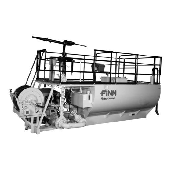
Summary of Contents for Finn HydroSeeder T170 SSA
- Page 1 9281 LeSaint Drive • Fairfield, Ohio 45014 Phone (513) 874-2818 • Fax (513) 874-2914 Parts Dept.: 1-800-229-8707 Sales: 1-800-543-7166 ® T170 HydroSeeder Parts and Operator’s Manual Model SSA Serial No. _____________ LBT170-SSA...
- Page 2 BLANK...
-
Page 3: Table Of Contents
Pump Parts ..........51 continued ® HydroSeeder is a registered trademark of Finn Corporation... - Page 4 Controls ..........52-53 Hydraulic System .
-
Page 5: Safety First
SAFETY FIRST With any piece of equipment, new or used, the most important part of its operation is SAFETY! Finn Corporation encourages you and your employees to familiarize yourselves with your new equipment and to stress safe operation. The first four pages of this manual are a summary of all the main safety aspects associated with this unit. -
Page 6: Safety Summary Section
Practice all other usual and customary safe working precautions; and above all, remember that safety is up to you. The FINN HydroSeeder ® is designed to mix and apply water, seed, fertilizer, agricultural lime and hydraulic mulch to the prepared seedbed. The resultant slurry from mixing one or more of the above materials may react causing harmful or deadly gasses within the tank. - Page 7 5. The driver of the carrying or towing vehicle is respon- 2. Never engage the clutch sible for the safety of the operator(s) of the machine. when both the recirculation Make sure the driver is aware and avoids all possible and discharge valves are hazards to the operator(s) of the machine, such as low closed.
- Page 8 Make sure your company’s plan meets all the requirements of 29 CFR 1910.146. including the following: 9. It is recommended that only authorized genuine FINN a) Drain, flush and ventilate tank interior. replacement parts be used on the machine.
- Page 9 CURRENT SET OF SAFETY DECALS Before entering the tank: 1. Drain, flush and ventilate tank interior. 2. Turn off engine and disconnect battery cables. 3. Provide continuous ventilation or proper breathing apparatus. HOT EXHAUST 4. Provide standby individual 012278 outside of tank able to communicate with person inside and able to haul Do not aim stream him out with lifeline if necessary.
-
Page 10: Definition Of Hydroseeding
MANUAL FOR ® FINN T170 HYDROSEEDERS This manual gives you step by step instructions for the operation and maintenance of the Finn ® HydroSeeder . For best results and to insure longer life of the equipment, please follow the instructions carefully. - Page 11 TRUCK MOUNTING CALCULATIONS: (WB x FL) – (WB x FE) = G WB x (RE + HW +RL) = G G + C must be equal to or less than CA (WB x FE) + (G x HW) = FL (WB x RE) + HW x (WB –...
-
Page 12: Attachments
Mounting the HydroSeeder to the truck must allow for tire clear- ance as well as frame twist. Place hard wood spacers along the length of truck rails or use Finn spring mounting kit (#011562) or equivalent. ATTACHMENTS: 1. Extension hoses for reaching remote areas are available in 50 ft. (15m) lengths. All connections are camlock quick operating fittings. -
Page 13: Pre Start Check
Turn thumb nut clockwise until stem rises to maximum height. b) Remove cap and fill cap with sodium (water soluble) base grease. (FINN part number 000698). Do not use lithium base (chassis lube) grease. c) Replace cap. -
Page 14: Valve Operation
11. Engage and disengage clutch to determine if it “snaps” in and out. 12. Install discharge boom assembly (if stored in location other than standard operating position). A. Tighten the wing bolt at the opening around the top of the vertical pipe and insure that discharge boom is secure B. - Page 15 Discharge Through Boom: Flow is through boom with no flow through closed recirculation valve (Figure 2). Flow through boom is controlled by engaging and disengaging slurry pump clutch. Do not use the discharge valve to control distance. Valve should be completely open. Control the spray volume and spray distance by adjusting the engine RPM.
-
Page 16: Starting Procedure
® The following tables show loading versus coverage rates for the T170 Finn HydroSeeder . Table A shows rates for “one step” applications. The coverage area is determined by the fiber mulch capacity of the ®... - Page 17 TABLE A Using Seed, Fertilizer and Mulch Unit Amount of Material in Tank (pounds(kilograms)) Coverage Area (sq. ft.(sq. m.)) Seed Fertilizer Mulch T170 172 (78) 200 (91) 750 (340) 21,780 (2023) Above Table is based on 1500 pounds of mulch, 400 pounds of fertilizer and 345 pounds of seed (8 pounds/1000 square feet) per acre.
-
Page 18: Tank Capacity Chart
TANK CAPACITIES CHART: T170 Top of Gallons in. (cm) from in. (cm) from Load Hatch (Liters) bottom 1700 (6435) 9.5 (24.1) 49.25 (125.1) 1750 Gallons 1600 (6055) 12 (30.5) 46.75 (118.7) 6625 Liters 1500 (5675) 14.25 (36.25) 44.5 (113) 1400 (5300) 16.5 (42) 42.25 (107.3) 1300 (4925) -
Page 19: Loading
LOADING (For wood fiber mulch, if liming see page 19): CAUTION: Take care not to lose pens, lighters, etc. from shirt pockets or drop pieces of paper or plastic bags into the tank, as these might plug the slurry system. 1. -
Page 20: Prior To Application
C. Fertilizer - Stand over hatch opening and drop the bag onto the bag cutter. Grasp both ends of the bag and dump material. D. All other additives - Consult with manufacturer for proper loading technique. 7. When all materials are loaded and in suspension, and the tank is full, move the agitator to neutral then full speed forward to insure all material is mixed. -
Page 21: Application Of Slurry
APPLICATION OF SLURRY: I. General Application Techniques DANGER: Do not spray toward power lines, transformers or other high voltage conductors. CAUTION: The driver of the carrying vehicle should remain alert for hazards to the operator, such as low power lines, hanging branches, etc. - Page 22 A. PUMP TAKE OFF SYSTEM OR HOSE REEL WITH REMOTE VALVE : 1. Open recirculation valve and close discharge valve and close remote valve at the end of the hose. 2. Engage clutch. When stream is flowing freely through the recirculation line, open the pump take off valve.
-
Page 23: Reloading
RELOADING PROCEDURE: 1. Start at step 2 in loading procedure on page 15. 2. After last load of the day refer to the cleaning and maintenance section of the manual on pages 24-39. ® LIMING WITH THE HydroSeeder ® In using large concentrations of granular solids through the HydroSeeder , it is advisable to keep the slurry moving through the pump at all times. -
Page 24: Trouble Shooting The Hydroseeder
15. With the clutch still engaged, open the discharge valve. CAUTION: To decrease pump wear and increase discharge distance, it may now be desirable to close the recirculation valve. However, the recirculation valve must be open BEFORE closing the discharge valve if the application of slurry is to be interrupted. - Page 25 c) Remove the nozzle, slowly and carefully. d) Clear the nozzle with the nozzle cleaning rod attached to the underside of the guard rail. DANGER: Severe injury can result from opening clamps when piping is hot. Before loosening any clamps, determine if the pipe is hot. If so, let it cool before attempting repair.
- Page 26 ® TROUBLE SHOOTING YOUR HydroSeeder Problem Probable Causes Suggested Solutions LEAKS: Tank bearing leaks. Lack of lubrication - Replace seal and follow lube seal worn. schedule. Bolts not tightened. Tighten uniformly to 25 ft. lbs. properly. Pressure Clamps. Rubber seal cracked, Replace, always grease seal pinched or torn.
- Page 27 ® TROUBLE SHOOTING YOUR HydroSeeder Problem Probable Causes Suggested Solutions Constant plugging Foreign material in slurry. Drain and clean out tank. Check during operation. storage for foreign materials. ® Constant plugging Loading HydroSeeder Reinstruct your operator. (See during loading and before tank is half full page 15).
-
Page 28: Cleaning And Maintenance
CLEANING AND MAINTENANCE: AFTER FIRST 4 - 8 HOURS OF OPERATION: 1. Check and adjust clutch - see page 32. DAILY: ® 1. Cleaning the HydroSeeder A. Fill the slurry tank to the center of the agitator shaft. B. Move agitator lever to full speed to flush off inside of tank top and walls. C. -
Page 29: Hydraulic System
The hydraulic oil filter must be replaced on schedule with a 10 micron filter – Finn part #021618. The hydraulic system relief is factory set at 2500... - Page 31 LUBRICATION AND FLUIDS CHART Ref. No. Location Lubricant Frequency Number Check Grease Level in Pressure Lubricator Daily Check Clutch Lever Bearings Weekly Grease Agitator Shaft Bearings Daily Grease Clutch Shaft Bearings Weekly Grease Discharge Swivels Weekly Check Engine Oil Level Daily Check Engine Oil and Filter See Engine Manual...
-
Page 33: Pump Parts
PUMP PARTS Ref. No. Part Number Description No. Req’d 005146 Suction Cover X0824SS Suction Cover Bolt Y08SS Suction Cover Nut 005150 O-Ring 005145 Impeller 006443 Mechanical Seal Assembly 005144 Pump Casing X0824SS Suction Cover Bolt W08FSS Suction Cover Washer 006444 Grease Retainer Seal 006450 Radial Bearing Slinger... -
Page 34: Pump Maintenance
PUMP MAINTENANCE SECTION: CAUTION: Pump maintenance to be done only while engine is not running, and battery cables are disconnected. A. FACTORY-TOLERANCES. 1. To check pump tolerances loosen the two clamps on the pump suction piping and remove the inlet elbow. - Page 35 D. INSTALLING NEW SEAL ASSEMBLY (#4) (Do not unwrap the new seal assembly until you are ready to install. All parts of the assembly are packed in sequence of installation.) 1. To replace the seal assembly (4), perform the above operations under cleaning and remove pump casing (5) by removing the three bolts (10B) holding the casing to the pump frame (10).
- Page 36 Figure 4...
-
Page 37: Power Take-Off Assembly
POWER TAKE-OFF ASSEMBLY Ref. No. Part Number Description No. Req’d 012069A Power Take Off Assembly includes: 100011 Clutch Body 100028 Pressure Plate 100341 Clutch Facing 100013 Adjusting Ring 100032 Ring Wear Plate 100026 Spring Lever 100018 Lever 100010 Pivot Lever Pin 100007 Retaining Ring 100024... -
Page 38: Clutch Maintenance
CARE AND OPERATION OF ROCKFORD POWER TAKE-OFF The following brief instructions are a simple outline of duties that the owner and operator must perform for long and satisfactory service from any Rockford Power Take-Off. CLUTCH ADJUSTMENT PROCEDURE: NOTE: Do not mix Sodium or Calcium base grease with Lithium grease. - Page 39 DISASSEMBLE THE POWER TAKE-OFF: (Refer to Figure 1 on page 22 for parts call out). 1. Remove all accessories or drives attached to the output shaft. ENGAGE THE CLUTCH. • Disconnect any linkage that may be attached to the clutch-actuating handle. •...
- Page 40 Finn recommends that a new pilot housing bore. They should not have side move- bearing is installed whenever the PTO assembly ment in the bore.
- Page 41 to separate the links (H30) from the levers • Tapered bore must fit snugly and securely on (H13). shaft. Pressure Plate: 3. Disassemble the sleeve and bearing sub-assembly. • Friction surface must not have heat cracks, must • Remove the three retainers (H32) and clevis smooth must flat...
- Page 42 snapring. Measure the dimension from the • Securely install the retainer (H32) in the groove bearing shoulder inside the carrier to the farthest of the clevis pin. edge of the snapring groove and compare with • Repeat the previous 3 steps to install links on below.
- Page 43 the adjusting ring counter-clockwise and reen- yoke. The other keyway will be located outside gage the clutch. Repeat until the clutch is the yoke. Install two woodruff keys (T15) in adjusted tight enough to hold the facings the cross shaft. aligned.
-
Page 44: Notes
NOTES... - Page 45 NOTES...
- Page 46 NOTES...
- Page 47 NOTES...
- Page 48 NOTES...
-
Page 49: Parts Section
T170 ® HydroSeeder Parts Manual Model SSA... - Page 50 WHEN ORDERING PARTS, BE SURE TO STATE SERIAL NUMBER OF MACHINE Parts Department: 1-800-229-8707 LBT170-SSA...
-
Page 51: Tank Top Parts
TANK TOP PARTS Ref. No. Part Number Description No. Req’d F170-0004 Tank Top 190047 Gasket 32’ 008582-01 Front Tank Top Support 008582-02 Rear Tank Top Support 012468-02 Swing Gate 080521 Spring Hinge 012468-01 Rear-Side Guard Rail 012477 Left-Rear Guard Rail 012474-03 Left-Rear Toe Rail 012471... - Page 52 WHEN ORDERING PARTS, BE SURE TO STATE SERIAL NUMBER OF MACHINE Parts Department: 1-800-229-8707 LBT170-SSA...
-
Page 53: Pump, Piping, And Discharge Assembly
PUMP, PIPING, AND DISCHARGE ASSEMBLY Ref. No. Part Number Description No. Req’d 005143 Pump Assembly (See pg. 51 for Parts) 002383 Pressure Lubricator 008189 Plunger 008190 Screw, Nut, Follower and Spring 160160 Coupling 160389 Pipe Nipple 012491 Suction Elbow/Bleed Valve Assembly 012491-02 Suction Elbow 160006... -
Page 54: Discharge Boom Assembly
DISCHARGE BOOM ASSEMBLY Ref. No. Part Number Description No. Req’d 012489 Discharge Boom Assembly Includes: 012489-16 Stand Pipe 012489-02 Lower Boom Pipe 012489-01 Upper Boom Pipe 012283 Swivel 010544 Brass Female Coupler 006513 Gasket, Coupler 012489-19 Boom Handle 011914 Knob, Handle Locking 012397* Swivel Repair Kit *Not Included with Assembly #012489... -
Page 55: Pump Parts
PUMP PARTS Ref. No. Part Number Description No. Req’d 005143 Pump Assembly Consisting of: 005146 Suction Cover 005150 O-Ring, Suction Cover X0824SS Bolt, Suction Cover 005144 Pump Casing X0828SS Bolt, Adjusting 006443 Seal Assembly 006444 Seal, Grease Retainer 006446 Thrust Bearing 006445 Radial Bearing 006447... - Page 56 WHEN ORDERING PARTS, BE SURE TO STATE SERIAL NUMBER OF MACHINE Parts Department: 1-800-229-8707 LBT170-SSA...
- Page 57 CONTROLS Ref. No. Part Number Description No. Req’d 012566-01 Control Tower Assembly (Includes Items 1-7) 011795 Control Tower F330-0026-01 Control Box w/ Cover (less components) Gauges, Switches, and Tower Wiring Harness (Order Separately-See pages 60-61) 008474 Throttle Control Assembly 008475 Input Lever 1 per 011954...
- Page 58 WHEN ORDERING PARTS, BE SURE TO STATE SERIAL NUMBER OF MACHINE Parts Department: 1-800-229-8707 LBT170-SSA...
- Page 59 HYDRAULIC SYSTEM Ref. No. Part Number Description No. Req’d 023652 90˚ Adapter 008293 Hydraulic Valve 023616 Straight Adapter FW71492 90˚ Adapter 008599 Hose 080649 Adapter 021617 Return Line Filter 021618 Filter Element 011783 Fill Cap 080329 Sight Gauge 022592 Tee Adapter 160236 Pipe Plug FW71550...
- Page 60 WHEN ORDERING PARTS, BE SURE TO STATE SERIAL NUMBER OF MACHINE Parts Department: 1-800-229-8707 LBT170-SSA...
-
Page 61: Agitator & Seal Assembly
AGITATOR AND SEAL ASSEMBLY Ref. No. Part Number Description No. Req’d 012529 Bearing and Seal Assembly Includes: 012527 Inner Clamping Ring w/Studs 1per 012528 Agitator Shaft Seal 1per 012525 Outer Clamping Ring 1per 012451 Flangette 1per 012450 Bearing 1per 012542 Flangette w/Lube Coupling 1per 008154... -
Page 62: Hatch Assembly
HATCH ASSEMBLY Ref. No. Part Number Description No. Req’d 005713 Hatch Assembly Includes: 005486 Hatch Liner 012638 Hatch Lid 005484 Bag Cutter X0848SS 1/2-13 UNC HHCS x 3” Lg. - Stainless Steel Y08LSS 1/2-13 UNC Lock Nut - Stainless Steel W08FSS 1/2”... -
Page 63: Hydraulic Agitator Drive
Tank Wall HYDRAULIC AGITATOR DRIVE Ref. No. Part Number Description No. Req’d 012333 Hydraulic Motor 012354 Hydraulic Motor Mount 012522-02 Rubber Bushing 012522-04 Insert 011780 Rigid Coupling 003055B Motor Bushing 055103 Agitator Bushing 190127-40 012625 Set Lock Collar WHEN ORDERING PARTS, BE SURE TO STATE WHEN ORDERING PARTS, BE SURE TO STATE SERIAL NUMBER OF MACHINE SERIAL NUMBER OF MACHINE... - Page 64 WHEN ORDERING PARTS, BE SURE TO STATE SERIAL NUMBER OF MACHINE Parts Department: 1-800-229-8707 LBT170-SSA...
-
Page 65: Electrical System
ELECTRICAL SYSTEM Part Number Description No. Req’d 012560 Tower Wiring Harness 012559 Engine Wiring Harness 012559-01 Horn Wiring Harness 020886 Horn Button 052076 Ignition Switch F330-0026-01 Control Box (See Pg. 52-53) 022119 Safety Switch 021198 Flasher w/Bracket 007274 Hourmeter 007958 Voltmeter 011489 Temperature Gauge... - Page 66 WHEN ORDERING PARTS, BE SURE TO STATE SERIAL NUMBER OF MACHINE Parts Department: 1-800-229-8707 LBT170-SSA...
-
Page 67: Power System
POWER SYSTEM Ref. No. Part Number Description No. Req’d 008576 Engine Assembly 012069A Clutch Assembly (See page 66-67) 022314 Pilot Bearing 012620 Radiator 012610 Rubber Mount 022452 Drain Cock 007678 JDR128455 Upper Radiator Hose 022450 Hose Clamp 023845 Lower Radiator Hose 022450 Hose Clamp 052378... - Page 68 1 Air Intake Assembly 13 Exhaust Assembly WHEN ORDERING PARTS, BE SURE TO STATE SERIAL NUMBER OF MACHINE Parts Department: 1-800-229-8707 LBT170-SSA...
-
Page 69: Air Intake And Exhaust Systems
AIR INTAKE AND EXHAUST SYSTEMS Ref. No. Part Number Description No. Req’d 008620 Air Intake Assembly (Includes Items 2-9) 012621 Air Cleaner Assembly 012622 Main Filter Element (3.75-E1) 1 per 012623 Safety Filter Element (3.75-E2) 1 per 012621A Flapper Valve 1 per 012621B Dust Load Indicator Gauge... - Page 70 WHEN ORDERING PARTS, BE SURE TO STATE SERIAL NUMBER OF MACHINE Parts Department: 1-800-229-8707 LBT170-SSA...
-
Page 71: Power Take-Off Assembly
POWER TAKE-OFF ASSEMBLY Ref. No. Part Number Description No. Req’d 012069A Power Take Off Assembly includes: 100011 Clutch Body 100028 Pressure Plate 100341 Clutch Facing 100013 Adjusting Ring 100032 Ring Wear Plate 100026 Spring Lever 100018 Lever 100010 Pivot Lever Pin 100007 Retaining Ring 100024... - Page 72 WHEN ORDERING PARTS, BE SURE TO STATE SERIAL NUMBER OF MACHINE Parts Department: 1-800-229-8707 LBT170-SSA...
- Page 73 Decal “1000 Gallons” 005187 Decal “800 Gallons” 007230 Decal “Service Daily” 005186 Decal “500 Gallons” 011690 FINN Name Plate 011662 Decal “PATENT NUMBERS” 020976 Decal “PATENT INFRINGEMENT” 023391 Decal “DIESEL FUEL ONLY” 012179 Decal “WARNING! DO NOT RUN WITHOUT GUARDS”...
-
Page 74: Discharge Hose Extensions
DISCHARGE HOSE EXTENSIONS Part Number Description No. Req’d TOWER TAKE OFF SYSTEM 007930-02 Hose Assembly, Discharge Extension - Tower As Ordered 007929 1-1/2” Hose w/ Nipples, 50 ft. 1 per 002191 Adapter 1 per 160768 Reducer Bushing 1 per 010544 Coupler 1 per 006513... - Page 75 RECOMMENDED SPARE PARTS, REPAIR KITS AND MISCELLANEOUS PARTS Part Number Description No. Req’d SPARE PARTS 000698 Grease, Pump Seal Lubricator 011919 Suction Pipe Seal 002820 Discharge Pipe Seal 006722 Recirculation Pipe Seal 006513 Nozzle Coupler Gasket 007469 Lube Sticks, Recirculation and Discharge Valves 011858 Air Cleaner Element JDR123442...
- Page 76 Hose Reel Wiring WHEN ORDERING PARTS, BE SURE TO STATE SERIAL NUMBER OF MACHINE Parts Department: 1-800-229-8707 LBT170-SSA...
-
Page 77: Hose Reel Assembly
HOSE REEL ASSEMBLY Ref. No. Part Number Description No. Req’d 008212 Hose Reel Assembly Includes: Drum Back Disc Front Disc Disc Sprocket Hub, Less Riser Flanged Riser 008144 Ring Gear Spacer Front Frame Back Frame Front Foot Back Foot Back Brace 008200 Chain with Connecting Link Pinion Gear... -
Page 78: Tool Kit
Tool Kit Part Number Description No. Req’d 008476 Nozzle, Long Distance 011703 Nozzle Assembly, Long Distance 001042 Nozzle, Long Distance 006512 Gasket, Nozzle 002191 Brass Male Adapter 160540 Close Nipple 160768 Reducer Bushing 011706 Nozzle Assembly, Wide Ribbon-Small 006604 Nozzle, Wide Ribbon-Small (50500) 002191 Brass Male Adapter 160766... - Page 79 BLANK LBT170-SSA...
- Page 80 Finn to verify said nonconformity and verify the continuing existence of the warranty period, Finn will provide a new part or a repaired part, whichever Finn elects, to replace the part found to be defective. Such parts will...
Need help?
Do you have a question about the HydroSeeder T170 SSA and is the answer not in the manual?
Questions and answers