Table of Contents
Advertisement
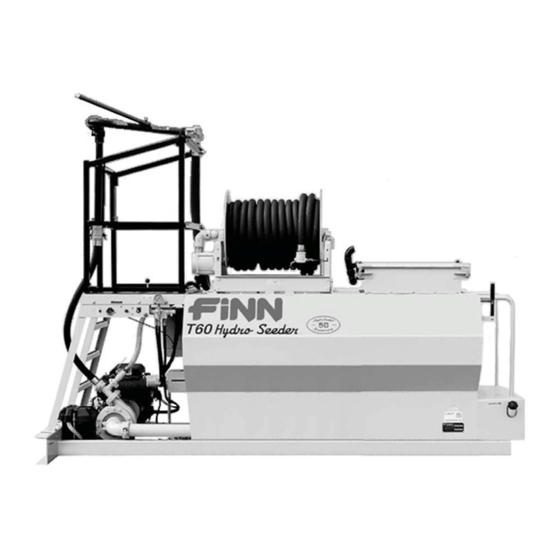
T60S HydroSeeder
Operator Instructions and Parts Manual
T60 CE ML1020
9281 LeSaint Drive • Fairfield, Ohio 45014
Phone (513) 874-2818 • Fax (513) 874-2914
Sales: 1-800-543-7166
CE-Compliant
Model ML
Serial No. _____________
Activate
Activate
Your Warranty
Your Warranty
By Registering
By Registering
TODAY!!!
TODAY!!!
®
Advertisement
Table of Contents

Related Manuals for Finn T60S HydroSeeder


Summary of Contents for Finn T60S HydroSeeder
- Page 1 Your Warranty By Registering By Registering TODAY!!! TODAY!!! 9281 LeSaint Drive • Fairfield, Ohio 45014 Phone (513) 874-2818 • Fax (513) 874-2914 Sales: 1-800-543-7166 T60S HydroSeeder ® CE-Compliant Operator Instructions and Parts Manual Model ML Serial No. _____________ T60 CE ML1020...
- Page 2 II II...
- Page 3 IF FINN CORPORATION DOES NOT HAVE YOUR COMPLETED REGISTRATION FORM ON FILE, YOUR WARRANTY CLAIM WILL BE DENIED. Once your FINN equipment has been registered, your FINN Limited Warranty will be activated per the warranty statement on the next page.
- Page 4 Follow the instruction sheet, on property damage sustained by a person claiming to be a third party how to use your Finn Oil Analysis Kit that comes with the Kit. Failure beneficiary of a surviving warranty under the law of any jurisdiction.
-
Page 5: Table Of Contents
Pump Maintenance........23 - 24 Continued . . . ® HydroSeeder is a registered trademark of the FINN Corporation... - Page 6 INDEX Pump Assembly Information ........25 ® Troubleshooting Your HydroSeeder .
-
Page 7: Safety First
SAFETY FIRST With any piece of equipment, new or used, the most important part of its operation is SAFETY! FINN Corporation encourages you and your employees to familiarize yourselves with your new equipment and stresses safe operation. The first five pages of this manual are a summary of the main safety aspects associated with this unit. -
Page 8: Hydroseeder ® Safety Summary Section
® HYDROSEEDER SAFETY SUMMARY SECTION It is important that operators of this machine are familiar with all safety aspects covered in this section and have read the entire Operator’s Manual before operating the machine. Always keep a copy of this manual with the machine. It is the responsibility of the operator of the machine to fully understand this safety summary section. - Page 9 6. Operator(s) of equipment should 3. The recirculation valve must be open and material never ride on the machine at flowing back into the tank when using the remote speeds of greater than 5 mph valve. A closed or plugged recirculation line will (8 km/h).
- Page 10 Drain, flush, and ventilate tank interior. Turn off engine, disconnect 8. It is recommended that only authorized, genuine battery cables, and perform FINN replacement parts be used on the machine. lockout/tagout procedures 9. Hydraulic fluid under pressure can penetrate the (29 CFR 1910.147).
- Page 11 CURRENT SET OF SAFETY DECALS WA R NING DANGER Wear proper eye protec tion when operating CONFINED SPACE HAZARD! Before entering tank: mac hine. 1. Drain, flush, and ventilate tank interior. F ailure to c omply 2. Turn off engine and disconnect battery cables. 3.
-
Page 12: Operation And Maintenance Section
MANUAL FOR THE FINN T60 SERIES II ® HYDROSEEDER This manual gives you step-by-step instructions for the operation and maintenance of the FINN ® T60 HydroSeeder . For best results and to ensure longer life of the equipment, please follow the instructions carefully. -
Page 13: Mounting The Hydroseeder
Mounting the HydroSeeder to the truck must allow for tire clearance and frame twist. Place hard wood spacers along the length of truck rails or use FINN spring mounting kit (part number 011562) or equivalent. ® 3. Place chains over the HydroSeeder and around truck bed and secure with binders. -
Page 14: Pre-Start Check
PRESSURE DISK stem rises to maximum height. 2. Remove cap and fill cap with GREASE sodium- (water soluble) base grease (FINN part number 000698). DO NOT use lithium- base (chassis lube) grease. 3. Replace cap. 4. Turn thumb nut counterclockwise until thumb nut is at the top of the stem. -
Page 15: Equipment Check
EQUIPMENT CHECK (CONTINUED) When thumb nut has moved down to within 1/2 in. (1.25 cm) of touching the cap, re-service the automatic pressure lubricator. 10. Check and clean the nozzles and hoses of any obstructions or foreign materials. 11. Check pump discharge, recirculation, and remote valve handles for free movement. VALVE OPERATION A. -
Page 16: Valve Operation (Platform/Boom Option)
VALVE OPERATION (CONTINUED) B. VALVE OPERATION (PLATFORM/BOOM OPTION) The platform option is equipped with two independently operated ball valves to control slurry flow (see Figure 3). With the platform option, discharge of the slurry is accomplished two different ways; either through the discharge boom or through a discharge hose that is coupled to the end of the discharge boom. -
Page 17: Starting Procedure
® The tables show loading versus coverage rates for the FINN T60S HydroSeeder . Table A shows rates for one-step applications. The coverage area is determined by the fiber mulch capacity of ®... - Page 18 TABLE A USING SEED, FERTILIZER, AND MULCH Unit Amount of Material in Tank in pounds (kilograms) Coverage Area Seed Fertilizer Mulch sq. ft. (sq. m) 46 (21) 53 (24) 200 (91) 5,790 (535) Table is based on 1,500 lbs. (680 kgs) of mulch, 400 lbs. (181 kgs) of fertilizer, and 345 lbs.
-
Page 19: Tank Capacity Chart
TANK CAPACITY CHART 600 Gallons BOTTOM T60S Inches (centimeters) Inches (centimeters) Gallons (Liters) from Top from Bottom (2271) 8.00 (20.3) 40.50 (102.9) (2082) 11.25 (28.6) 37.25 (94.6) (1893) 14.25 (36.2) 34.25 (87.0) (1703) 16.75 (42.5) 31.75 (80.6) (1514) 19.50 (49.5) 29.00 (73.7) (1325) 22.00 (55.9) -
Page 20: Loading
LOADING PROCEDURE Take care not to lose pens, lighters, etc. from shirt pockets, or drop pieces of paper or plastic bags into the tank, as these might plug the slurry system. Failure to comply could result in death or serious injury. Failure to comply could also result in product or property damage. - Page 21 LOADING PROCEDURE (CONTINUED) 6. Start loading dry material, loading the lightest material first. Agitator control should be in full REVERSE for mixing. A. Seed – Cut open the seed bag and dump contents into slurry tank. (When using inoculant, add it in the tank along with the seed.) When using quick-swelling seeds, load them just prior to application.
-
Page 22: Loading And Mixing Bfm, Fgm, Smm And Other Highly Viscous
LOADING AND MIXING BFM, FGM, SMM AND OTHER HIGHLY VISCOUS SLURRIES 1. With pump clutch disengaged (turned off), agitator control in the NEUTRAL position and hydraulic system off, start engine and allow it to warm up. See STARTING PROCEDURE. 2. After engine has warmed up, turn on the hydraulics system by flipping the hydraulics toggle switch to the HYDRAULICS ON position (all the way up). - Page 23 LOADING AND MIXING BFM, FGM, SMM AND OTHER HIGHLY VISCOUS SLURRIES (CONTINUED) 7. Start loading dry material, loading the lightest materials first. Agitator control should be in full REVERSE for mixing. Seed - Cut open the seed bag and dump contents into slurry tank. (When using inoculant, add it in the tank along with the seed.) When using quick-swelling seeds, load them just prior to application.
-
Page 24: Prior To Application
PRIOR TO APPLICATION Operators should familiarize themselves with the area to be seeded and develop a plan to ensure uniform application. A. STANDARD AND HOSE REEL ONLY UNITS 1. Develop a plan for communication between the operator and the driver of the carrying or towing vehicle to signal for start, stop, turn, etc. -
Page 25: Application Of Slurry
APPLICATION OF SLURRY I. GENERAL APPLICATION TECHNIQUES Do not spray toward power lines, transformers or other high voltage conductors. Failure to comply will result in death or serious injury. The driver of the carrying vehicle should remain alert for hazards to the operator, such as low power lines, hanging branches, etc. -
Page 26: Ii. Procedures When Using Hoses
APPLICATION OF SLURRY (CONTINUED) II. PROCEDURES WHEN USING HOSES Always pump clear water through the hose before pumping mulch. If the inside hose liner is dry, it may dewater the mulch, causing the hose to plug. DISCHARGE THROUGH HOSE OR HOSE REEL WITH REMOTE VALVE 1. -
Page 27: Cleaning And Maintenance
CLEANING AND MAINTENANCE DAILY ® 1. Cleaning the HydroSeeder A. Fill slurry tank to center of agitator shaft with clean water. B. Move agitator lever to full speed (forward or reverse) to flush off inside of tank top and walls. C. -
Page 28: Seasonal And Winter Storage Maintenance
The hydraulic oil filter must be replaced on schedule with a 25 micron absolute filter – FINN part number 023914. The hydraulic system relief is factory-set at 2,250 psi (15,513 kPa). -
Page 29: Pump Maintenance
CLEANING AND MAINTENANCE (CONTINUED) PUMP MAINTENANCE NOTE: Refer to Figure 6 for callouts in PUMP MAINTENANCE section. Pump maintenance should be done only while engine is not running and battery cables are disconnected. Failure to comply could result in minor or moderate personal injury. Failure to comply could also result in product or property damage. - Page 30 CLEANING AND MAINTENANCE (CONTINUED) PUMP MAINTENANCE (CONTINUED) C. CLEANING (CONTINUED) 3. To remove pump impeller, take the pump impeller wrench, which is stored in the tool box, and position it so that the hole is aligned with any of the eight tapped holes in the front of the pump casing (4).
-
Page 31: Pump Assembly Information
Drive Hub Locknut Suction Cover Bolt Clutch Retainer Suction Cover Washer Retainer Bolt Radial Lip Seal 12LW Retainer Lockwasher Casing Bearing Electric Clutch Bearing Bolt Clutch Spacer Bearing Lockwasher Pump Frame Frame Bearing NOTE: See Parts Manual for FINN part numbers. -
Page 32: Troubleshooting Your Hydroseeder
® TROUBLESHOOTING YOUR HYDROSEEDER ® Because of the tremendous work load usually placed upon the HydroSeeder , minor malfunctions will occur from time to time. If not remedied immediately, they could lead to poor performance and damage to the equipment. This section describes symptoms, possible causes, and the corrective actions to take. - Page 33 ® TROUBLESHOOTING YOUR HYDROSEEDER (CONTINUED) 2. Plugging or clogging (Continued): B. If the recirculation system is not working: 1. Disengage (turn off) the pump clutch and stop engine. 2. Remove clamps attaching recirculation valve assembly. 3. Slide rubber seals back and remove valve assembly. 4.
-
Page 34: Leaks
® TROUBLESHOOTING YOUR HYDROSEEDER Problem Probable Causes Suggested Solutions LEAKS: Tank Bearing Lack of lubrication – seals worn Replace seals and follow lube schedule. Bolts not torqued properly Tighten uniformly to 25 lb–ft (34 N•m). Pressure Pipe Clamps Rubber seal cracked, pinched, torn Replace, always grease seal before or missing clamping shut. -
Page 35: Valve
® TROUBLESHOOTING YOUR HYDROSEEDER Problem Probable Causes Suggested Solutions VALVE: Valve stuck Frozen Thaw out ice and lubricate; leave valves in OPEN position during cold weather storage. Constant plugging during Foreign material in slurry Drain and clean out tank; check operation storage for foreign materials. - Page 36 Figure 7 – Lubrication and Adjustment Points...
-
Page 37: Lubrication And Fluids Chart
LUBRICATION AND FLUIDS CHART (Reference Figure 7) Ref. No. Location Lubricant Frequency Number Check Grease Level in Automatic Pressure Lubricator Daily Grease Agitator Shaft Bearings Daily Grease Discharge Swivel Daily Check Engine Oil Level Daily Change Engine Oil and Filter See Engine Manual Grease Pump Bearings Weekly... - Page 38 8 ft. (244 cm) 11 ft. 2 in. (340 cm) 5 ft. 9 in. (175 cm) NOTE: Hose Reel and Platform with Boom are optional. Height with platform option...
-
Page 39: Technical Specifications
® FINN T60 SKID HYDROSEEDER TECHNICAL SPECIFICATIONS POWER ............Kohler CH730, 23.5 hp (17.5 kW), 2 cylinder, OHV, air cooled gas ENGINE SAFETY SYSTEM ......Low oil pressure, high temperature shutoff TANK SIZE ............ 600 gallon (2,270 L) liquid capacity 500 gallon (1,890 L) working capacity LOADS PER ACRE ¹... -
Page 41: Parts Section
T60S HydroSeeder ® CE-Compliant Parts Section Model ML T60 CE ML1015... - Page 42 WHEN ORDERING PARTS, BE SURE TO STATE SERIAL NUMBER OF MACHINE T60 CE ML1020...
-
Page 43: Suction, Discharge And Recirculation Piping
SUCTION, DISCHARGE AND RECIRCULATION PIPING Part Number No. Req’d Ref. Standard or Loaded or Standard or Loaded or Hose Reel Only Platform Only Description Hose Reel Only Platform Only 080713 080713 Clump Assembly 080366 080366 Pipe Clamp 002439 002439 Clamp Gasket 1 per 1 per 002868... - Page 44 WHEN ORDERING PARTS, BE SURE TO STATE SERIAL NUMBER OF MACHINE T60 CE ML1020...
-
Page 45: Clutch / Pump Assembly
CLUTCH / PUMP ASSEMBLY Ref. Ref. Part Number Description No. Req’d 080489 Pump Suction Cover 0X0720 Suction Cover Bolt (7/16 - 14 x 1-1/2 in. Long) 000Y07 Suction Cover Nut (7/16 - 14) 080499 O-Ring 080488 Pump Impeller ... - Page 46 WHEN ORDERING PARTS, BE SURE TO STATE SERIAL NUMBER OF MACHINE T60 CE ML1020...
-
Page 47: Hydraulic System
HYDRAULIC SYSTEM Ref. No. Ref. Part Number Description No. Req’d 012044 Pressure Gauge 012087 MSAE - MJIC Adapter 023616 MNPT - MJIC Adapter 023911 FNPT - MSAE Adapter 055232 MSAE - MJIC Adapter 053019 MSAE - MJIC 45°... -
Page 48: Hydraulic Pump Drive Assembly
HYDRAULIC PUMP DRIVE ASSEMBLY Ref. Part Number Description No. Req’d 3/8 X 1 in. Lg. Bolt 080642 Hydraulic Pump F60-0016-03 Hydraulic Pump Mounting Plate 3/8 in. Hex Nut 080807 Coupling Half 5/8 in. Bore with 5/32 Keyway 080809 Coupling Sleeve 080808 Coupling Half 1 in. -
Page 49: Hydraulic Agitator Drive Assembly
HYDRAULIC AGITATOR DRIVE ASSEMBLY Ref. Part Number Description No. Req’d 1/2 X 1-1/2 in. Lg. Bolt 080482 Hydraulic Motor F60-0016-01 Torque Arrestor Plate 1/2 Hex Nut 080523 Rigid Coupling Assembly 007420 Bearing and Seal Assembly (See page 40) 005081-02 Agitator Drive Stub Shaft with 3/8 Keyway NOT SHOWN... - Page 50 BEARING ASSEMBLY NOTE: BEARING ASSEMBLY (007420) INCLUDES ITEMS #1 – #10. AGITATOR SHAFT THROUGH BACKSIDE NOTE: TO TIGHTEN, TURN NUT NOT BOLT. TORQUE TO OUTSIDE 25 lb-ft (34 N m). OF TANK WALL DO NOT OVER TORQUE. AGITATOR SHAFT ASSEMBLY NOTE: AGITATOR SHAFT ASSEMBLY (ITEM #14) INCLUDES ITEMS #15 THRU #26.
-
Page 51: Bearing / Agitator Assembly
BEARING / AGITATOR ASSEMBLY Ref. No. Ref. Part Number Description No. Req’d Y08SS Agitator Nut 4 per 012605 Bevel Sealing Washer 4 per 007705 Grease Fitting 1 per 007211-02 Flangette w/ Lube Coupling 1 per 003022 Bearing 1 per... -
Page 52: Discharge Boom
DISCHARGE BOOM OPTION Ref. No. Ref. Part Number Description No. Req’d 080708 Boom Weldment Z0632SCP 3/8-16 x 2 in. Long Square Head Cap Screw 080559-01 Boom Handle 003299 Discharge Balance Torsion Spring 080560-02 Adjusting Collar ... -
Page 53: Hatch Assembly
HATCH ASSEMBLY Ref. Part Number Description No. Req’d 080674 Hatch Lid 005565 Hatch Lid Lanyard 005433 Soft Latch 080675 Hatch Liner F60-0002-01 Hatch Shim 2 (as required) 070627 Hatch Lid Hinge 002909 Handle NOT SHOWN 190044 Foam Gasket 12.5 (Ft) WHEN ORDERING PARTS, BE SURE TO STATE SERIAL NUMBER OF MACHINE T60 CE ML1020... -
Page 54: Common Loose Parts And Engine
WHEN ORDERING PARTS, BE SURE TO STATE SERIAL NUMBER OF MACHINE T60 CE ML1020... - Page 55 COMMON LOOSE PARTS Ref. Part Number Description No. Req’d F60-0005 Platform (Platform and Loaded Option Only) F75-0013 Right Support Angle F75-0012 Left Support Angle 080590-01 Platform Support Angle 080731 Fill Port Weldment 005280 Fill Port Plug 080378 Male Nyglass Coupler F60-0002 Tank Top 190044...
-
Page 56: Guard Rails
GUARD RAILS Ref. Part Number Description No. Req’d 080762 Right Guard Rail 080818 Gate 013122 Gate Spring 080817 Left Guard Rail 080536-18 Cross Rail 080765 CE Front Toe Rail F75-0008 Boom Support Plate NOT SHOWN 080766 Ladder 080773 CE Foot Pedal Guard 080767 CE Ladder Hand Rail WHEN ORDERING PARTS, BE SURE TO STATE... -
Page 57: Tool Kit
Narrow Fan Nozzle Assembly 006605 Narrow Fan Nozzle 080260 Male Adapter 160750 Reducer Bushing 006515 Coupler Gasket 012681A FINN Beige Aerosol Paint 080535 Remote Valve Assembly 012083 Full Port Ball Valve 080260 Male Adapter 080261 Female Coupler 160307 Close Nipple... -
Page 58: Control Panel (Standard)
SECTION A-A HYDRAULICS ON HYDRAULICS OFF HOUR METER PUMP ON PUMP OFF KEY SWITCH CONTROL PANEL (STANDARD UNIT)* Ref. No. Ref. Part Number Description No. Req’d 080833 Control Box Enclosure 080835 Control Box Sub-panel 008793 Momentary Toggle Switch ... - Page 59 CONTROL PANEL (STANDARD UNIT) WIRING WHEN ORDERING PARTS, BE SURE TO STATE SERIAL NUMBER OF MACHINE T60 CE ML1020...
-
Page 60: Control Panel (Hose Reel Only)
SECTION A-A HYDRAULICS ON HYDRAULICS OFF HOUR METER PUMP ON PUMP OFF KEY SWITCH CONTROL PANEL (HOSE REEL ONLY UNIT) Ref. No. Ref. Part Number Description No. Req’d 080833 Control Box Enclosure 080835 Control Box Sub-panel 008793 Momentary Toggle Switch ... -
Page 61: Control Panel (Platform Only)
CONTROL PANEL (HOSEREEL ONLY UNIT) WIRING WHEN ORDERING PARTS, BE SURE TO STATE SERIAL NUMBER OF MACHINE T60 CE ML1020... - Page 62 SECTION A-A HYDRAULICS ON HYDRAULICS OFF HOUR METER PLATFORM PUMP ON GROUND PUMP OFF KEY SWITCH CONTROL PANEL (PLATFORM ONLY UNIT) Ref. No. Ref. Part Number Description No. Req’d 080833 Control Box Enclosure 080835 Control Box Sub-panel 008793 Momentary Toggle Switch ...
- Page 63 CONTROL PANEL (PLATFORM ONLY UNIT) WIRING WHEN ORDERING PARTS, BE SURE TO STATE SERIAL NUMBER OF MACHINE T60 CE ML1020...
-
Page 64: Control Panel (Loaded)
SECTION A-A HYDRAULICS ON HYDRAULICS OFF HOUR METER PLATFORM PUMP ON GROUND PUMP OFF KEY SWITCH CONTROL PANEL (LOADED UNIT) Ref. No. Ref. Part Number Description No. Req’d 080833 Control Box Enclosure 080835 Control Box Sub-panel 008793 Momentary Toggle Switch ... - Page 65 CONTROL PANEL (LOADED UNIT) WIRING WHEN ORDERING PARTS, BE SURE TO STATE SERIAL NUMBER OF MACHINE T60 CE ML1020...
-
Page 66: Hose Reel Button Box Assembly
HOSE REEL BUTTON BOX ASSEMBLY Ref. Part Number Description No. Req’d 080780 Hose Reel Button Box Assembly 080757 Push Button 080779 Modified Enclosure 080304 Liquid Tight Fitting 080783 Push Button Mounting Latch 080784 Push Button Contact Block WHEN ORDERING PARTS, BE SURE TO STATE SERIAL NUMBER OF MACHINE T60 CE ML1020... - Page 67 THIS PAGE LEFT BLANK INTENTIONALLY WHEN ORDERING PARTS, BE SURE TO STATE SERIAL NUMBER OF MACHINE T60 CE ML1020...
- Page 68 WHEN ORDERING PARTS, BE SURE TO STATE SERIAL NUMBER OF MACHINE T60 CE ML1020...
-
Page 69: Hose Reel
HOSE REEL Ref. Part Number Description No. Req’d 080801 Hose Reel With 1/2 HP (12V) Motor 008188 Electric Motor 080801-01 Friction Brake Assembly 080801-02 90° Inlet 080801-03 Bearing Housing Sub Assembly 080801-04 Spindle 1-1/2 in. Female Pipe - Ductile 080801-06 Gooseneck - 11 in. - Page 70 WHEN ORDERING PARTS, BE SURE TO STATE SERIAL NUMBER OF MACHINE T60 CE ML1020...
-
Page 71: Decals
DECALS Ref. Part Number Description No. Req’d 023174 Decal "FINN" 012661-06 Decal "T60" 011595 Decal "Hydro Seeder" 012260 "IMPORTANT" Metal Plate Decal "Noise Protection" Decal "CAUTION! Hydraulic System Instructions . . ." Decal "CAUTION!" Fall Hazard!" ...
Need help?
Do you have a question about the T60S HydroSeeder and is the answer not in the manual?
Questions and answers
how the seal kit goes in pump the correct way
To correctly install the seal kit in the pump of a Finn T60S HydroSeeder:
1. Remove the pump casing by taking out the four bolts that hold the casing and casing bearing to the pump frame.
2. Clean all parts, including the pump shaft.
3. Install the radial lip seal with the cavity side facing inward.
4. Reattach the casing and casing bearing to the clutch housing using the four bolts.
5. Lubricate the ceramic seat (in its neoprene holder) with light oil and place it squarely into the seal recess on the shaft.
6. Lubricate the inside of the bellows assembly with light oil. Ensure the steel ring is glued to the end of the assembly.
7. Slide the bellows assembly onto the shaft and push it until the steel ring contacts the ceramic seat.
8. Install the seal spring on the pump impeller hub.
This answer is automatically generated