Table of Contents
Advertisement
Quick Links
Operator Instructions and Parts Manual
T170 ML2016 Rev. A
9281 LeSaint Drive • Fairfield, Ohio 45014
Phone (513) 874-2818 • Fax (513) 874-2914
Sales: 1-800-543-7166
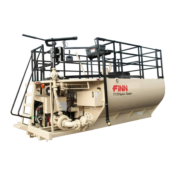
T170 HydroSeeder
Model ML
Serial No. _____________
Activate
Activate
Your Warranty
Your Warranty
By Registering
By Registering
TODAY!!!
TODAY!!!
®
Advertisement
Table of Contents

Related Manuals for Finn HydroSeeder T170 ML


Summary of Contents for Finn HydroSeeder T170 ML
- Page 1 Activate Activate Your Warranty Your Warranty By Registering By Registering TODAY!!! TODAY!!! 9281 LeSaint Drive • Fairfield, Ohio 45014 Phone (513) 874-2818 • Fax (513) 874-2914 Sales: 1-800-543-7166 T170 HydroSeeder ® Operator Instructions and Parts Manual Model ML Serial No. _____________ T170 ML2016 Rev.
- Page 2 For Office Use Only Date Update Description Code 11/12/15 Initial release ML1112 09/29/16 Revision A: new identification light bar ML2016...
- Page 3 IF FINN CORPORATION DOES NOT HAVE YOUR COMPLETED REGISTRATION FORM ON FILE, YOUR WARRANTY CLAIM WILL BE DENIED. Once your FINN equipment has been registered, your FINN Limited Warranty will be activated per the warranty statement on the other side of this notice.
- Page 4 Follow the instruction sheet, on property damage sustained by a person claiming to be a third party how to use your Finn Oil Analysis Kit that comes with the Kit. Failure beneficiary of a surviving warranty under the law of any jurisdiction.
-
Page 5: Table Of Contents
Lubrication and Fluids Chart ........41 Continued to next page. ® HydroSeeder is a registered trademark of the FINN Corporation... - Page 6 D. Installing New Seal Assembly ....... 43 ® FINN T170 HydroSeeder Technical Specifications ....44 - 45 Parts Section.
-
Page 7: Safety First
SAFETY FIRST With any piece of equipment, new or used, the most important part of its operation is SAFETY! FINN Corporation encourages you and your employees to familiarize yourselves with your new equipment and stresses safe operation. The first five pages of this manual are a summary of the main safety aspects associated with this unit. -
Page 8: Hydroseeder ® Safety Summary Section
® HYDROSEEDER SAFETY SUMMARY SECTION It is important that operators of this machine are familiar with all safety aspects covered in this section and have read the entire Operator’s Manual before operating the machine. Always keep a copy of this manual with the machine. It is the responsibility of the operator of the machine to fully understand this safety summary section. - Page 9 6. Operator(s) of equipment should 3. Recirculation valve must be open and material never ride on the machine at flowing back into the tank when using the remote speeds of greater than 5 mph valve. A closed or plugged recirculation line will (8 km/h).
- Page 10 9. It is recommended that only authorized, genuine Provide continuous ventilation or proper FINN replacement parts be used on the machine. breathing apparatus. 10. Do not use ether cold start fluid, if engine is If tank must be entered, personnel entering the equipped with glow plug-type preheater, or other tank must be tethered to a lifeline.
- Page 11 CURRENT SET OF SAFETY DECALS WARNING DANGER CONFINED SPACE HAZARD! (Reference: OSHA 29 CFR 1910.146) Before entering tank: BURN HAZARD! Contents could be 1. Drain, flush, and ventilate tank interior. under pressure. 2. Turn off engine and disconnect battery cables. DO NOT come in 3.
-
Page 12: Operation And Maintenance
OPERATION AND MAINTENANCE MANUAL ® FOR FINN T170 HYDROSEEDERS This manual provides instructions for the operation and maintenance of the FINN T170 ® HydroSeeder . For best results and to ensure longer life of the equipment, please follow these instructions carefully. For your safety, read the entire manual before operating this unit. -
Page 13: General Mounting Guidelines
® Mounting the HydroSeeder to the truck must allow for tire clearance and frame twist. Place hard wood spacers along the length of truck rails or use FINN spring mounting kit (part number 011562) or equivalent. -
Page 14: Attachments
ATTACHMENTS 1. Extension hoses for reaching remote areas are available in 50 ft. (15 m), 100 ft. (30m), and 200 ft. (60m) lengths. All connections are camlock quick-operating fittings. The hose is connected to the end of the discharge boom in place of a nozzle. The nozzle is connected to the end of the hose and controlled by the person on the ground. -
Page 15: Equipment Check
Turn thumb nut clockwise until stem rises to maximum DISK height. b) Remove cap and fill cap with sodium-(water soluble) GREASE base grease. (FINN part number 000698). Do not use lithium-base (chassis lube) grease. Figure 3 – Automatic c) Replace cap. Pressure Lubricator d) Turn thumb nut counterclockwise until the thumb nut is at the top of the stem. -
Page 16: Two-Valve Operation
TWO-VALVE OPERATION ® This HydroSeeder is equipped with two independently operated ball valves to control DISCHARGE VALVE slurry flow. One is located in the recirculation line (SHOWN CLOSED) below the platform, and the other is located in the discharge line above the platform. The valve handles should be positioned as shown in Figures 4 through 6 for the particular application required. -
Page 17: Extension Hose Or Hose Reel Through Remote Port
3. EXTENSION HOSE OR HOSE REEL THROUGH REMOTE PORT: Flow is through the open recirculation valve with no flow through the closed boom discharge valve (Figure 6). Flow through the hoses is started and stopped by engaging or disengaging the slurry pump clutch. -
Page 18: Control Panel Guide
CONTROL PANEL GUIDE NOTE: This information is to explain the function and use of the control panel when starting the unit. DO NOT start the unit at this point. Refer to STARTING PROCEDURE section for actual operation. SYSTEM POWER UP The control panel is powered from the engine battery connection from the engine harness connector. - Page 19 EMERGENCY STOP EMERGENCY STOP EQUIPMENT A critical safety component of this equipment is the Emergency Stop (E-Stop) switch. This device is located next to the control panel, and the button is colored red to be visible and to indicate a "stop" function based on color association.
- Page 20 CONTROL PANEL GUIDE AND SYSTEM OPERATION MENU NAVIGATION The control unit has three Engine Data Alarm navigation buttons which are Symbol Indicator configured as softkeys. The system softkeys are used to navigate between displays, Engine select menu items and change Data data.
- Page 21 MAIN MENU ACCESS To access the Main Menu, press any of the three navigation buttons. The unit will display a softkey popup window defining the available navigation possibilities. Select the Main Menu using the center softkey as shown. MAIN MENU NAVIGATION Access the main menu using the center softkey.
- Page 22 FAULT CODES Engine fault codes (active and stored) are generated by the engine ECU and communicated to the control panel. ACTIVE FAULT CODES The control system reads standard messages to indicate active fault codes. When a fault is active the control system activates a popup fault display containing a check engine icon, fault code number (if applicable),...
- Page 23 MAINTENANCE TIMER The control system provides an engine maintenance timer feature. The maintenance timer is a countdown timer and indicates the amount of engine runtime remaining until maintenance is due. The maintenance timer is configurable and resettable by the operator. If the system is powered but the engine is not running maintenance hours will not be accumulated.
- Page 24 BACKLIGHT SETTING The LCD backlight is adjustable from 0 to 100%. To adjust the LCD backlight enter the Main Menu and navigate to the “Display Setup” menu using the “ ” softkey. When highlighted enter the Display Setup menu by selecting the “ ” softkey.
- Page 25 DISPLAY MODE SETTING Two display formats are available: “Single” display and “Dual” display formats. To access the display format setting, enter the Main Menu. Navigate to the “Display Setup” menu entry using “ ” softkey. When highlighted, enter the Display Setup menu by selecting the “...
- Page 26 ENGINEERING UNITS Displayed engineering units can be configured for Pressure, Temperature and Volume. To access the engineering unit’s settings, enter the Main Menu. Navigate to the “Display Setup” menu entry using “ ” softkey. When highlighted enter the Display Setup menu by selecting the “...
- Page 27 DISPLAY LIST SINGLE DATA FORMAT DUAL DATA FORMAT MISCELLANEOUS DISPLAYS...
- Page 28 ABOUT MENU The About Menu indicates the software information used for programming the control unit. ENGINE SETTINGS The Engine Settings are factory-specified. This feature is password-protected to ensure the correct use of the engine in this unit.
-
Page 29: Starting Procedure
® The following tables show loading versus coverage rates for the FINN T170 HydroSeeder Table A shows rates for one-step applications. The coverage area is determined by the fiber ®... - Page 30 TABLE A Using Seed, Fertilizer, and Mulch Unit Amount of Material in Tank in pounds (kilograms) Coverage Area Seed Fertilizer Mulch sq. ft. (sq. m) T170 172 (78) 200 (91) 750 (340) 21,780 (2,023) Table is based on 1,500 lbs. (680 kg) of mulch, 400 lbs. (181 kg) of fertilizer and 345 lbs. (156 kg) of seed at 8 lb (3.6 kg) / 1,000 sq.
- Page 31 Top of Load Hatch 1,750 Gallons 6,625 Liters Bottom T170 Gallons in. (cm) From in. (cm) From Top (Liters) of Load Hatch Bottom 1,700 (6,435) 9.5 (24.1) 49.25 (125.1) 1,600 (6,055) 12 (30.5) 46.75 (118.7) 44.5 (113) 1,500 (5,678) 14.25 (36.2) 1,400 (5,300) 16.5 (42) 42.25 (107.3)
-
Page 32: Loading
(turn off) pump clutch. G. Replace nozzle and gasket in discharge boom. 5. Continue filling tank with water. 6. Increase engine speed to full RPM. Governed speed of the engine on the FINN HydroSeeder® should be 2,500 RPM under load. - Page 33 LOADING (FOR WOOD FIBER MULCH, IF LIMING SEE LIMING WITH ® THE HYDROSEEDER SECTION) - CONTINUED 7. Start loading dry material, loading the lightest material first. Agitator control should be in full REVERSE for mixing. A. Seed – Cut open the seed bag open and dump contents into slurry tank. (When using inoculant, add it in the tank along with the seed.) When using quick swelling seeds, load them just prior to application.
- Page 34 G. Replace coupler gasket in the remote valve coupler (or in boom on the platform option). 5. Continue filling tank with water. 6. Increase engine speed to full RPM. Governed speed of the engine on the FINN HydroSeeder® should be 2,500 RPM under load.
- Page 35 LOADING AND MIXING BFM, FGM, SMM AND OTHER HIGHLY VISCOUS SLURRIES (CONTINUED) 7. Start loading dry material, loading the lightest materials first. Agitator control should be in full REVERSE for mixing. Seed - Cut open the seed bag and dump contents into slurry tank. (When using inoculant, add it in the tank along with the seed.) When using quick-swelling seeds, load them just prior to application.
-
Page 36: Prior To Application
PRIOR TO APPLICATION 1. Operator(s) should familiarize themselves with the area to be seeded and develop a plan to ensure uniform application. 2. Develop a plan for communication between operator and driver of the carrying or towing vehicle to signal for start, stop, turn, etc., through the use of the signal horn. 3. -
Page 37: Discharge Through The Boom
APPLICATION OF SLURRY (CONTINUED) 3. Application of wood and paper fiber: Whenever possible, aim the stream towards the ground to create a surface with small pockmarks which will help get seed in contact with ground. Do not allow the stream to blast away the surface of the seed bed. 4. -
Page 38: Extension Hose System Without Remote Valve
APPLICATION OF SLURRY (CONTINUED) 5. If another load is to be done, see RELOADING PROCEDURE. If finished for the day, follow the clean-up procedure and flush out the hose. The recirculation valve must be open when using a remote valve. Failure to comply will result in serious injury or death. -
Page 39: Liming With The Hydroseeder
This keeps the solids from settling in the lines, and creating a clog. This unit was designed for the application of agricultural-grade lime or FINN-HLL liquid lime only. PROCEDURE 1. -
Page 40: Troubleshooting Your Hydroseeder
TROUBLESHOOTING YOUR HYDROSEEDER ® ® Because of the tremendous work load usually placed upon the HydroSeeder , minor malfunctions will occur from time to time. If these are not remedied immediately, they could lead to poor performance and damage to the equipment. This section describes symptoms, possible causes, and the corrective action(s) to take. - Page 41 TROUBLESHOOTING YOUR HYDROSEEDER ® (CONTINUED) 3. Obstruction in the pump, which can be determined by a drop in pressure. If the drop in pressure is accompanied by a frothy or whitish discharge stream, the blockage is in the suction line or sump area. To clear the pump: A.
- Page 42 Troubleshooting Chart Symptom Probable Cause Suggested Solutions LEAKS Tank Bearing Lack of lubrication - seal worn. Replace seal and follow lube schedule. Bolts not tightened. Tighten uniformly to 25 lb-ft (34 N•m). Pressure Pipe Clamps Rubber seal cracked, pinched, Replace, always grease seal torn or missing.
- Page 43 Troubleshooting Chart Symptom Probable Cause Suggested Solutions VALVE Valve stuck Frozen Thaw out ice and lubricate; leave discharge valve in the open position during storage. Constant plugging Foreign material in slurry. Drain and clean out tank; check during operation sump area for foreign materials. Constant plugging ®...
-
Page 44: Cleaning And Maintenance
CLEANING AND MAINTENANCE AFTER FIRST 4 TO 8 HOURS OF OPERATION Check and adjust clutch. See clutch manual. DAILY ® 1. Cleaning the HydroSeeder A. Fill slurry tank to center of agitator shaft with clean water. B. Move agitator lever to full speed (FORWARD and REVERSE) to flush off inside of tank top and walls. -
Page 45: Weekly Or Every 40 Hours Of Operation
The hydraulic oil should be replaced per the lubrication schedule or if the oil becomes milky or gives off a burnt odor. The hydraulic oil filter must be replaced on schedule with a 25 micron absolute filter (FINN part number 008703). The hydraulic system relief is factory-set at 2,800 psi (19,305 kPa). - Page 46 Figure 9 – Lubrication and Adjustment Points...
-
Page 47: Lubrication And Fluids Chart
LUBRICATION AND FLUIDS CHARTS LUBRICATION CHART Ref. No. Location Lubricant Frequency Number Check Grease Level in Pressure Lubricator Daily Check Clutch Lever Bearings Weekly Grease Agitator Shaft Bearings Daily Check Fuel Level Daily Grease Discharge Boom Swivels Daily Check Engine Oil Level Daily Change Engine Oil and Filter See Engine Manual... -
Page 48: Clump Maintenance Section
CLUMP MAINTENANCE Clump maintenance to be done only while engine is not running, and battery cables are disconnected. Failure to comply could result in minor personal injury, or product or property damage. A. FACTORY TOLERANCES To check clump tolerances, loosen the two clamps on the pump suction piping and remove the inlet elbow. -
Page 49: Installing New Seal Assembly
D. INSTALLING NEW SEAL ASSEMBLY Do not unwrap the new seal assembly until you are ready to install. All parts of the assembly are packed in sequence of installation. 1. To replace seal assembly, perform the steps in CLEANING of the CLUMP MAINTENANCE section, and remove pump casing by removing three bolts holding the pump casing to the clump housing. - Page 50 16 ft. 8 in. (508 cm) 7 ft. 9 in. (236 cm) 8 ft. 10 in. (269 cm)
-
Page 51: Finn T170 Hydroseeder Technical Specifications
® FINN T170 HYDROSEEDER TECHNICAL SPECIFICATIONS POWER ..........Cummins QSF 2.8 L Diesel, Tier 4F, 65 hp (48kW), with over-center clutch. Vibration isolated. Controls include: clutch, agitator direction and speed, discharge boom and recirculation control valves, engine throttle, safety horn and engine start/stop ENGINE SAFETY SYSTEM ....Low oil pressure, Electronic Engine Control and Monitoring... - Page 52 NOTES...
-
Page 53: Parts Section
T170 HydroSeeder ® Parts Section Model ML WHEN ORDERING PARTS, BE SURE TO STATE SERIAL NUMBER OF MACHINE T170 ML2016 Rev. A... - Page 54 WHEN ORDERING PARTS, BE SURE TO STATE SERIAL NUMBER OF MACHINE T170 ML2016 Rev. A...
-
Page 55: Structure And Railing
FUEL TANK POLY HATCH DETAIL DETAIL STRUCTURE AND RAILING Ref. Part Number Description No. Req’d 013149 Swing Gate 013122 Gate Spring F330-0108 Main Tank Top F170-0015 Left Side Toe Rail 008639 Left Side Guard Rail F330-0120 Front Tank Top Support 012703 Slide Gate 012737... - Page 56 STRUCTURE AND RAILING Ref. Part Number Description No. Req’d F330-0084 Rear Corner Toe Rail 002191 2-1/2 in. Male Brass Adapter 002190 Dust Cap with Gasket - Main Tank Drain 006513 Dust Cap Gasket 190018 2 in. Wide Conformable Safety Walk A/R (ft.) 005944 LED Identification Light...
- Page 57 THIS PAGE LEFT BLANK INTENTIONALLY WHEN ORDERING PARTS, BE SURE TO STATE SERIAL NUMBER OF MACHINE T170 ML2016 Rev. A...
- Page 58 WHEN ORDERING PARTS, BE SURE TO STATE SERIAL NUMBER OF MACHINE T170 ML2016 Rev. A...
-
Page 59: Discharge Boom Assembly
DISCHARGE BOOM ASSEMBLY Ref. No. Ref. Part Number Description No. Req’d 012763 Lower Boom Discharge Weldment 012283 2-1/2 in. Straight Swivel 012762 Upper Boom Discharge Weldment 013159 Boom Discharge Handle Weldment 012726-01 Boom Stand Pipe ... - Page 60 WHEN ORDERING PARTS, BE SURE TO STATE SERIAL NUMBER OF MACHINE T170 ML2016 Rev. A...
-
Page 61: Engine
ENGINE Ref. No. Part Number Description No. Req’d 075880 QSF 2.8 Engine 075880-ECM Engine ECM (Supplied with Engine) 008768 ECM Mounting Isolators 008735 Rear Left Engine Foot 008737 Front Left Engine Foot 008762 Hydraulic Pump 008758 Upper Radiator Support 023438 Radiator Isolator 008757 Upper Radiator Support Bracket... - Page 62 ENGINE Ref. No. Part Number Description No. Req’d 008809 Engine Oil Canister Element 008808 120 V Alternator 008830 QSF 2.8 Fan Belt 008854 Oil Dipstick and Guide Assembly 008854-01 Oil Dipstick 008854-02 Oil Dipstick Guide Tube 008855 Oil Fill Cap Assembly 085303-18 Engine Isolators NOT SHOWN...
- Page 63 THIS PAGE LEFT BLANK INTENTIONALLY WHEN ORDERING PARTS, BE SURE TO STATE SERIAL NUMBER OF MACHINE T170 ML2016 Rev. A...
- Page 64 WHEN ORDERING PARTS, BE SURE TO STATE SERIAL NUMBER OF MACHINE T170 ML2016 Rev. A...
-
Page 65: Engine Sheet Metal
ENGINE SHEET METAL Ref. Part Number Description No. Req’d 008664 Rear Sheetmetal Mount Leg (Long) 008784 Sheetmetal Support Bracket 008740 Rear Sheetmetal Cover 008742 Top Sheetmetal Cover 055669 Door Positioning Hinge F260-0006-03 Hinge Spacer F260-0006-02 Radiator Cap Cover 008745 Rear Sheetmetal Mount Leg (Short) F170-0026 Radiator Cover Mount Bracket F170-0020... - Page 66 17 18 15 16 Primary Filter Element Secondary Filter Element WHEN ORDERING PARTS, BE SURE TO STATE SERIAL NUMBER OF MACHINE T170 ML2016 Rev. A...
-
Page 67: Air Intake And Exhaust Systems
AIR INTAKE AND EXHAUST SYSTEM Ref. Part Number Description No. Req’d 012991 Rain Cap Assembly 023471 Exhaust Elbow 055501 Muffler Clamp 008752 Exhaust Pipe Extension 008759 DOC Muffler 008796 Muffler Mounting Bracket 008829 Muffler Mounting Bracket Band 008798 DOC Mounting Plate 008797 DOC Hanger 008804... - Page 68 SECTION A-A WHEN ORDERING PARTS, BE SURE TO STATE SERIAL NUMBER OF MACHINE T170 ML2016 Rev. A...
-
Page 69: Control Station And Control Box
CONTROL STATION AND CONTROL BOX Ref. No. Ref. Part Number Description No. Req’d F170-0029 Guard Rail Control Box Mounting Bracket 008800 Control Box Mounting Plate 012970 Emergency Stop (E-stop) with Enclosure 008801 Control Box Cover 008802 Control Box Cover Plexiglass 055669 Door Positioning Hinge ... - Page 70 SECTION A-A WHEN ORDERING PARTS, BE SURE TO STATE SERIAL NUMBER OF MACHINE T170 ML2016 Rev. A...
- Page 71 ENGINE RELAY BOX Ref. No. Ref. Part Number Description No. Req’d 075888-01 Relay Box Enclosure 075892 Relay Box Back Panel 008838 Fuse Box 008839 Mega 250A Fuse 008840 Ametek Switch 075893 Starter Relay 080303 Cord Grip ...
- Page 72 REFERENCE CLUMP ASSEMBLY WHEN ORDERING PARTS, BE SURE TO STATE SERIAL NUMBER OF MACHINE T170 ML2016 Rev. A...
-
Page 73: Clump, Piping And Discharge Assembly
CLUMP, PIPING AND DISCHARGE ASSEMBLY Ref. Part Number Description No. Req’d 011736 Victaulic Pipe Clamp 011919 Victaulic Pipe Clamp Seal 1 per 008259 90º Pipe Elbow 011882 Toe-Goe Pipe 012722 Suction Valve Flange Weldment 012058 Flanged Suction Gate Valve 012491 Suction Valve Bleeder Valve Assembly 012491-02 Suction Elbow Weldment... - Page 74 WHEN ORDERING PARTS, BE SURE TO STATE SERIAL NUMBER OF MACHINE T170 ML2016 Rev. A...
-
Page 75: Clutch / Pump (Clump) Assembly
CLUTCH / PUMP (CLUMP) ASSEMBLY Ref. No. Ref. Part Number Description No. Req’d 005146 Pump Suction Cover 005150 O-ring 005145 Pump Impeller 006443 Mechanical Shaft Seal 005144 Pump Casing 006444 Grease Retainer 005446 Flange Pilot Bearing ... - Page 76 CLUTCH / PUMP (CLUMP) ASSEMBLY Ref. No. Ref. Part Number Description No. Req’d 012783-02 Lock Washer 012783-01 Drive Shaft Nut 190123-24 Clutch Key 100024 Adjusting Lock 002383 Automatic Pressure Lubricator NOT SHOWN X Lock Bolt for Adjustment Lock ...
- Page 77 THIS PAGE LEFT BLANK INTENTIONALLY WHEN ORDERING PARTS, BE SURE TO STATE SERIAL NUMBER OF MACHINE T170 ML2016 Rev. A...
- Page 78 DETAIL A WHEN ORDERING PARTS, BE SURE TO STATE SERIAL NUMBER OF MACHINE T170 ML2016 Rev. A...
-
Page 79: Controls
CONTROLS Ref. Part Number Description No. Req’d 008672 Agitator Control Handle 008673 Agitator Handle Pivot 022202 Black Handle Grip 085148 U-Bolt 005161 Rubber Strap with "S" Hooks 004996 Pipe Plug 012777 Recirculation Handle F330-0102 Agitator Control Box 012780-05 Recirculation Valve Rod Weldment 006737 Ball Joint 2 Per... - Page 80 BEARING ASSEMBLY 2 in. AGITATOR SHAFT NOTE: BEARING ASSEMBLY (012529) THROUGH BACK SIDE INCLUDES ITEMS #1 – #6. APPLY (1) SOLID, CONTINUOUS BEAD OF SILICONE ADHESIVE AROUND OUTER EDGE ON THE INSIDE FACE OF THE CLAMPING RING BEFORE INSTALLATION. OUTSIDE OF TANK WALL NOTE: TO TIGHTEN, TURN NUT - NOT THE BOLT.
-
Page 81: Agitator And Bearing Assemblies
AGITATOR AND BEARING ASSEMBLIES Ref. No. Ref. Part Number Description No. Req’d 012527 Agitator Clamping Ring 1 per 012528 Agitator Shaft Seal 1 per 012525 Agitator Bearing Clamping Ring 1 per 012451 Flangette 1 per 012450 Bearing 1 per... - Page 82 WHEN ORDERING PARTS, BE SURE TO STATE SERIAL NUMBER OF MACHINE T170 ML2016 Rev. A...
-
Page 83: Hydraulic System
HYDRAULIC SYSTEM Ref. No. Ref. Part Number Description No. Req’d 008545 FNPT - MSAE Adapter 008845 MNPT - MJIC 90° Elbow Adapter 008606 MSAE - MJIC Adapter 008660 MNPT - MJIC Adapter 008689 SAE Run Tee ... - Page 84 HYDRAULIC SYSTEM Ref. No. Ref. Part Number Description No. Req’d 080329 Hydraulic Level Sight Gauge 160236 Pipe Plug 160520 Close Nipple 085157 MSAE - MJIC 45° Elbow Adapter 085276 Dump Valve 085276-01 Dump Valve Coil 008843 MSAE Plug ...
-
Page 85: Hydraulic Agitator Drive
REFERENCE the AGITATOR and BEARING ASSEMBLIES HYDRAULIC AGITATOR DRIVE Ref. Part Number Description No. Req’d 012333 Hydraulic Motor 012354 Hydraulic Motor Mount F330-0029 Agitator Coupling Guard 012522-02 Rubber Bushing 012522-04 Torque Arm Insert 011780 Rigid Coupling 003055B Motor Bushing 055103 Agitator Bushing 190127-40 012625... -
Page 86: Discharge Hose Extensions
DISCHARGE HOSE EXTENSIONS BOOM TAKE OFF SYSTEM Part Number Description No. Req’d 007930-02 Boom Discharge Extension Hose Assembly As Ordered 008315-05 1-1/2 in. x 50 ft. Extension Hose with Nipples 002191 2-1/2 in. Male Brass Adapter 160768 2-1/2 x 1-1/2 in. Reducer Bushing 010544 2-1/2 in. - Page 87 DISCHARGE HOSE EXTENSIONS HOSE REEL SYSTEM Part Number Description No. Req’d 061359 1-1/4 in. Hose Reel Discharge Hose As Ordered 004832-20 1-1/4 in. x 200 ft. Rubber Hose with Nipples 002158 1-1/2 in. Female Coupler 006515 1-1/2 in. Coupler Gasket 160756 1-1/2 x 1-1/4 in.
- Page 88 DETAIL A DETAIL A WHEN ORDERING PARTS, BE SURE TO STATE SERIAL NUMBER OF MACHINE T170 ML2016 Rev. A...
-
Page 89: Hose Reel Assembly
HOSE REEL ASSEMBLY Ref. No. Ref. Part Number Description No. Req’d 080302 Flanged Riser 080302G Hose Reel Riser Gasket 008144 Hose Reel Gear 008200 Hose Reel Chain (69 in.) 008433 Pinlock with Brackets Assembly 008313 Idle Side Bearing ... - Page 90 To Dump Valve To Brand Valve WHEN ORDERING PARTS, BE SURE TO STATE SERIAL NUMBER OF MACHINE T170 ML2016 Rev. A...
-
Page 91: Hydraulic System
HOSE REEL HYDRAULIC SYSTEM Ref. No. Ref. Part Number Description No. Req’d 008693-01 1/2 in. Hydraulic Hose x 170 in. 008693-02 1/4 in. Hydraulic Hose x 23 in. 008693-03 1/2 in. Hydraulic Hose x 134 in. 008693-04 1/4 in. - Page 92 17 18 (Inside of Railing - Both Sides of Tank) LEFT SIDE OF UNIT WHEN ORDERING PARTS, BE SURE TO STATE SERIAL NUMBER OF MACHINE T170 ML2016 Rev. A...
-
Page 93: Decals
DECALS Ref. No. Ref. Part Number Description No. Req’d 023174 "FINN" Decal ® 011595 "HydroSeeder " Decal --------- "WARNING! Fall Hazard" Decal --------- "1,500 Gallon" Decal --------- "1,000 Gallon" Decal --------- "800 Gallon" Decal --------- "Service Daily"... -
Page 94: Recommended Spare Parts And Repair Kits
RECOMMENDED SPARE PARTS AND REPAIR KITS RECOMMENDED SPARE PARTS Part Number Description No. Req’d 000698 Automatic Pressure Lubricator Grease (1 lb Can) 011919 Suction Pipe Seal - 5 in. 008472 Suction Pipe Seal - 5 in. x 4 in. Reducer 002820 Discharge Pipe Seal - 2-1/2 in. -
Page 95: Tool Kit
Automatic Pressure Lubricator Grease (1 lb Can) 020365 Multi-Purpose Grease Cartridge 007469 Lube Sticks For Discharge and Recirculation Valves (Box of 24) 012681A Touch-Up Paint (FINN Beige - Aerosol) 012305 Adhesive Label (Remove Aerosol Can) Engine Operator's Manual ® HydroSeeder...
Need help?
Do you have a question about the HydroSeeder T170 ML and is the answer not in the manual?
Questions and answers