Finn HydroSeeder T330 Parts And Operator's Manual
Hide thumbs
Also See for HydroSeeder T330:
- Practical service manual for the parts professional (51 pages) ,
- Operator instructions and parts manual (100 pages)

Related Manuals for Finn HydroSeeder T330


Summary of Contents for Finn HydroSeeder T330
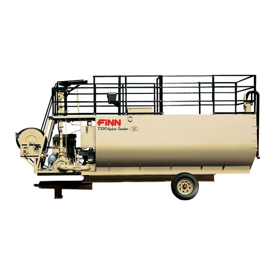
- Page 1 9281 LeSaint Drive • Fairfield, Ohio 45014 Phone (513) 874-2818 • Fax (513) 874-2914 Sales: 800-543-7166 ® T280/330 HydroSeeder Parts and Operator’s Manual Model SE Serial No. _____________ LBT289-T330-SE...
- Page 2 NOTES...
-
Page 3: Table Of Contents
Definition of Hydroseeding ........6 The Finn HydroSeeder® & How It Works ......6 Mounting The HydroSeeder®... - Page 4 INDEX CONTINUED OPERATION & MAINTENANCE Cont'd . . . Cleaning and Maintenance ........26-27 After First 4-8 Hours of Operation.
-
Page 5: Safety First
SAFETY FIRST With any piece of equipment, new or used, the most important part of its operation is SAFETY! Finn Corporation encourages you and your employees to familiarize yourselves with your new equipment and to stress safe operation. The first five pages of this manual are a summary of all the main safety aspects associated with this unit. -
Page 6: Safety Summary Section
The FINN HydroSeeder® is designed to mix and apply water, seed, fertilizer, agricultural lime and hydraulic mulch to the prepared seedbed. The resultant slurry from mixing one or more of the above materials may react causing harmful or deadly gasses within the tank. - Page 7 driver and/or the operator(s). All personnel should 2. Never engage the clutch review and be familiar with stop/start signals between when both the recirculation the driver and operator(s) before going into operation. and discharge valves are Only the operator should be located on the platform closed.
- Page 8 29 CFR 1910.146. including the following: 9. It is recommended that only authorized genuine FINN Drain, flush and ventilate tank interior. replacement parts be used on the machine. Turn off engine and disconnect battery cables 10.
- Page 9 CURRENT SET OF SAFETY DECALS...
-
Page 10: Operation & Maintenance
THE FINN HYDROSEEDER® AND HOW IT WORKS: The Finn HydroSeeder® will apply seed, fertilizer and/or lime, wood fiber mulch, or stabilizing materials in any prescribed or desired combination. The materials placed in the HydroSeeder® slurry-tank are mixed with water and kept in suspension by a dual agitation process, recirculation of slurry and mechanical agitation, thus forming a slurry that is pumped to the discharge assembly and directed onto the seed bed by the operator. -
Page 11: Truck Mounting Calculations
TRUCK MOUNTING CALCULATIONS: (WB x FL) – (WB x FE) = G WB x (RE + HW -RL) = G G + C must be equal to or less than CA (WB x FE) + (G x HW) = FL (WB x RE) + HW x (WB –... -
Page 12: Attachments
Place hard wood spacers along the length of truck rails or use Finn Spring Mounting Kit (#011562) or equivalent. ATTACHMENTS: 1. Extension hoses for reaching remote areas are available in 50 ft. (15m) lengths. All connections are camlock quick operating fittings. -
Page 13: Pre Start Check
6. Radio Remote Control. The radio remote control option provides the operator with pump on/off con- trol, throttle control, and engine shutdown at the end of the hose. With control of the engine throttle, the operator can precisely adjust the pump flow to whatever output the situation requires (i.e., for close-up work around buildings). -
Page 14: Two Valve Operation
Turn thumb nut clockwise until stem rises to maximum height. SPRING b) Remove cap and fill cap with sodium (water soluble) base grease. PRESSURE (FINN part number 000698). Do not use lithium base (chassis DISK lube) grease. c) Replace cap. -
Page 15: Discharge Through Boom
WARNING: Never engage the slurry pump clutch when both valve handles are positioned as shown Figure 4. Both valves are closed and will result in extreme heat generation that will cause damage or bodily injury if the slurry pump is running. 1. -
Page 16: Starting Procedure
DANGER: Recirculation valve must be open and material flowing back into tank when using a remote valve. A closed or plugged recirculation line will cause extreme heat resulting in damage and/or bodily injury. STARTING PROCEDURE: CAUTION: See safety section of the manual (pages 2-4) before operating the machine. -
Page 17: Faceplate
FACEPLATE The keypad on the PowerView is a capacitive touch sensing system. There are no mechanical switches to stick or wear out. It operates in extreme temperatures, with gloves, through ice, snow, mud, grease, etc. When the key is touched, feedback is provided by flashing the screen. The keys on the keypad perform the following functions (refer to Figure 7): Menu Key The Menu Key is used to either enter or exit the menu screens. -
Page 18: Stored Fault Codes
Stored Fault Codes The PowerView Display will store any fault codes GO TO 4-UP DISPLAY generated by the engine and display them along with ENGINE CONFGURATION STORED FAULT CODES a text description. To access these fault codes: ADJUST BACKLIGHT ADJUST CONTRAST 1. - Page 19 ® The following tables show loading versus coverage rates for the Finn HydroSeeder . Table A shows rates for ®...
-
Page 20: Tank Capacity Chart
Top of Load Hatch TITAN280 Gallons in. (cm) from in. (cm) from 2750 Gallons (Liters) top of load hatch bottom 10400 Liters 2750 (10410) 8 (20.3) 58.5 (148.6) 2700 (10220) 11.75 (29.8) 54.75 (139.1) 2600 (9840) 13.75 (34.9) 52.75 (134) 2500 (9465) 15.5 (39.4) 51 (129.5) -
Page 21: Loading (For Wood Fiber Mulch)
G. Replace nozzle and gasket in discharge boom. 4. Continue filling tank with water. 5. Increase engine speed to full RPM. Governed speed of the engine on the Finn HydroSeeder® should be 2,550 to 2,600 RPM under load. 6. Start loading dry material, loading the lightest material first. Agitator control should be in full reverse for mixing. -
Page 22: Prior To Application
C. Fertilizer - Stand over hatch opening and drop the bag onto the bag cutter. Grasp both ends of the bag and dump material. D. All other additives - Consult with manufacturer for proper loading technique. 7. When all materials are loaded and in suspension, and the tank is full, move the agitator to neutral then full speed forward to insure all material is mixed. -
Page 23: Application Of Slurry
APPLICATION OF SLURRY: I. GENERAL APPLICATION TECHNIQUES DANGER: Do not spray toward power lines, transformers or other high voltage con- ductors. CAUTION: The driver of the carrying vehicle should remain alert for hazards to the operator, such as low power lines, hanging branches, etc. Driver should never start or stop abruptly. -
Page 24: Pump Take-Off System Or Hose Reel W/Remote Valve
A. PUMP TAKE OFF SYSTEM OR HOSE REEL WITH REMOTE VALVE : 1. Open recirculation valve and close discharge valve and close remote valve at the end of the hose. 2. Engage clutch. When stream is flowing freely through the recirculation line, open the pump take off valve. -
Page 25: Hose Work W/Radio Remote
C. HOSE WORK WITH RADIO REMOTE: 1. Begin with the engine around 1/4 throttle (1,400 RPM). 2. Close recirculation valve. If using an extension hose connected to the discharge boom, open the dis- charge valve. If using the hose reel, close the discharge valve and open the pump take off valve to the hose reel. -
Page 26: Troubleshooting Your Hydroseeder
5. Aim the discharge boom assembly into an open area away from any persons, obstructions or high volt- age power lines. 6. Move the throttle to approximately 1/2 engine speed. 7. Engage the clutch, and move the throttle to full engine speed. A stream of water should be coming from the end of the recirculation pipe beside the hatch opening, as well as from the boom. - Page 27 D. Limit recirculation time as much as possible. E. Open pump suction bleed valve to exhaust air trapped in the pump or suction line. Close valve as soon as the air stops. 2. Plugging or clogging: DANGER: Turn off engine and disconnect battery cables before working on equip- ment.
- Page 28 4. Obstruction in the sump area, which is located at the bottom of the tank on the inside where the suc- tion pipe is attached: A. The easiest way to clear the sump is to back flush through the discharge plumbing with the water supply hose.
- Page 29 ® TROUBLESHOOTING YOUR HYDROSEEDER Problem Probable Causes Suggested Solutions Pump loses prime - lacks Too much agitation Slow the agitator distance - leaves excessive Pump worn Reset pump tolerance page 32 amount in tank (100 gal Suction partially plugged Clean out machine see pages 26-27 (378 liters) or more) Nozzle worn or plugged Clean nozzles, replace if necessary...
-
Page 30: Cleaning And Maintenance
® TROUBLESHOOTING YOUR HYDROSEEDER Problem Probable Causes Suggested Solutions PUMP CONT'D: Will not turn Frozen Warm housing to melt ice Jammed with fertilizer or lime Remove cover and clean interior Impeller rusted to suction cover plate Pull cover and remove rust CAUTION: Do not turn the shaft backwards with a pipe wrench - this will unscrew the impeller from the shaft. -
Page 31: Seasonal And Winter Storage Maintenance
12. Add fuel stabilizer to fuel tank. HYDRAULIC SYSTEM: The hydraulic system on your Finn HydroSeeder® is designed to give trouble free service, if maintained. The most important areas of maintenance are the hydraulic oil and filtration. The reservoir holds 50 gallons of Mobil DTE-13M or equivalent hydraulic oil. -
Page 33: Lubrication Chart
LUBRICATION CHART Ref. No. Location Lubricant Frequency Number Check Grease Level in Pressure Lubricator Daily Check Clutch Lever Bearings Weekly Grease Agitator Shaft Bearings Daily Check Fuel Level Daily Grease Discharge Swivels Daily Check Engine Oil Level Daily Check Engine Oil and Filter See Engine Manual Grease Pump Bearings Weekly... - Page 34 Figure 16 - Clump Parts...
-
Page 35: Clump Parts
CLUMP PARTS Ref. No. Part Number Description No. Req’d 011759 Suction Cover X0824SS Suction Cover Bolt 0Y08SS Suction Cover Nut 011920 O-Ring X0824SS Suction Cover Bolt WF08SS Suction Cover Washer 011758 Impeller 012730 Clump Casing 006443 Mechanical Shaft Seal 006444 Grease Retainer 005446 Flange Pilot Bearing... -
Page 36: Clump Maintenance Section
CLUMP MAINTENANCE SECTION: CAUTION: Clump maintenance to be done only while engine is not running, and bat- tery cables are disconnected. A. FACTORY-TOLERANCES 1. To check clump tolerances loosen the two clamps on the pump suction piping and remove the inlet elbow. - Page 37 D. INSTALLING NEW SEAL ASSEMBLY (DO NOT UNWRAP THE NEW SEAL ASSEMBLY UNTIL YOU ARE READY TO INSTALL. ALL PARTS OF THE ASSEMBLY ARE PACKED IN SEQUENCE OF INSTALLATION.) 1. To replace the seal assembly (9), perform the above operations under cleaning and remove pump casing (8) by removing the three bolts (39) holding the clump casing (8) to the clutch body (33).
- Page 38 Pressure Lubricator (Includes Items #41-43) NOTE: Item #19 (10¨ Clutch Assembly Kit) Includes Items #20-36) Figure 17 - Clump Assembly...
- Page 39 CLUMP ASSEMBLY Ref. No. Part Number Description No. Req’d 011759 Suction Cover 011920 O-Ring 011758 Impeller 006443 Mechanical Shaft Seal 012730 Clump Casing 006444 Grease Retainer 005446 Flange Pilot Bearing 012733 Seal 012734 Bearing Retainer Ring 012729 Clump Shaft 012731 Bearing 012732 SN-11 Nut...
-
Page 40: Notes
NOTES... -
Page 41: Notes
NOTES... - Page 42 NOTES...
- Page 43 NOTES...
- Page 44 NOTES...
- Page 45 T280/330 HydroSeeder ® Parts Manual Model SE LBT289-T330-SE...
- Page 46 NOTES...
-
Page 47: Pictorial Reference
PICTORIAL REFERENCE STRUCTURE & RAILING CONTROLS (Pages 44-45) (Pages 62-63) HATCH ASSEMBLY CONTROL BOX (Pages 46-47) WIRING (Pages 64-65) DISCHARGE BOOM ASSY (Pages 48-49) CLUMP, PIPING & DISCHARGE ASSEMBLY (Pages 58-59) CLUMP ASSEMBLY (Pages 60-61) AGITATOR & SEAL ASSY ENGINE & RADIATOR (Pages 66-67) (Pages 50-51) GROUND LEVEL... - Page 48 WHEN ORDERING PARTS, BE SURE TO STATE SERIAL NUMBER OF MACHINE...
-
Page 49: Structure & Railing
STRUCTURE & RAILING Ref. No. Part Number Description No. Req’d 012700 Swing Gate 012755 Spring Hinge F330-0074 Control Box Mount F330-0081 Boom Holddown 012488-02 Rear Tank Top Support F330-0085 Left Rear Toe Rail 012706 Left Rear Guard Rail 012488-01 Front Tank Top Support F330-0063 T330 Tank Top F280- 0003... - Page 50 WHEN ORDERING PARTS, BE SURE TO STATE SERIAL NUMBER OF MACHINE...
-
Page 51: Hatch Assembly
HATCH ASSEMBLY Ref. No. Part Number Description No. Req’d 012711 Hatch Lid 070627 Hatch Lid Hinge 085152 Rubber Stud Mount 002909 Hatch Handle 005433 Soft Latch 005487-04 Side Hatch Lid Gasket 005487-03 Side Gasket Strip Retainer Strap 012714-04 Front/Back Hatch Lid Gasket 012714-03 Front/Back Gasket Retainer Strap 012751... - Page 52 NOTE: ITEM #1 (DISCHARGE BOOM ASSEMBLY) INCLUDES ITEMS #2 - #7. WHEN ORDERING PARTS, BE SURE TO STATE SERIAL NUMBER OF MACHINE...
-
Page 53: Discharge Boom Assembly
DISCHARGE BOOM ASSEMBLY Ref. No. Part Number Description No. Req’d 012764 Discharge Boom Assembly 012763 Lower Boom Discharge Weldment 012283 2-1/2" Straight Swivel 012762 Upper Boom Discharge Weldment 012756 Boom Discharge Handle 012726-01 Boom Stand Pipe 010544 2-1/2" Female Coupler 006513 2-1/2"... -
Page 54: Engine Sheet Metal
REF: REF: CLUMP CLUMP, PIPING ASSEMBLY & DISCHARGE VIEW A (SEE PAGES 60-61) (SEE PAGES 58-59) (See Page 51) REF: ENGINE SHEET METAL (SEE PAGES 52-53) WHEN ORDERING PARTS, BE SURE TO STATE SERIAL NUMBER OF MACHINE... - Page 55 VIEW A ENGINE & RADIATOR Ref. No. Part Number Description No. Req’d 023864 4045T Tier 2 Engine Assembly 012611 Oil Fill Extension JDR123442 Serpentine Fan Belt 011747 Pusher Fan F816-0008-01 Fan Guard F816-0008-02 Fan Guard Mounting Strap 052651-04 Top Radiator Bracket F330-0093 Fan Shroud F330-0100...
- Page 56 WHEN ORDERING PARTS, BE SURE TO STATE SERIAL NUMBER OF MACHINE...
- Page 57 ENGINE SHEET METAL Ref. No. Part Number Description No. Req’d 055669 Lock Positioning Hinge F260-0006-02 Radiator Cap Cover F260-0006-03 Hinge Spacer F330-0069 Radiator Shroud F330-0038 Air Deflector 012738 Radiator Mount 012753 Front Engine Mount 052397 Rear Engine Foot 007433 Rubber Shock Mount 007887 Snubbing Washer 052697-02...
- Page 58 WHEN ORDERING PARTS, BE SURE TO STATE SERIAL NUMBER OF MACHINE...
-
Page 59: Air Intake & Exhaust Systems
AIR INTAKE & EXHAUST SYSTEM Ref. No. Part Number Description No. Req’d 012626 Air Intake Assembly (Includes Items #2-16) 012646 Air Cleaner Assembly (Includes Items #2-12) 012621 Air Cleaner 012623 Safety Filter Element (3.75-E2) 1 per 012622 Main Filter Element (3.75-E1) 1 per 012621D Filter Cap... - Page 60 SAFETY SWITCHES DOOR E-STOP SWITCH SWITCH DOOR SWITCH (Black) (White) (White) (White) (White) (Black) (Black) E-STOP SWITCH ENGINE CONNNECTIONS WIRES FROM FLASHING DEERE HARNESS LIGHT TERMINAL RAIL (Black) (Green) STARTER RELAY (Black) Battery Cable STARTER (Black) (Red) FROM CONTROL CABLE ALTERNATOR (Orange) From Deere Harness...
-
Page 61: Engine Wiring Diagram
ENGINE WIRING DIAGRAM Part Number Description No. Req’d 022891 Starter Relay 011851 Battery (12 Volt) 011770 Battery Box 007091 Ground Strap 008171 Battery Cable - Red 031350 Battery Cable - Black 075523 Oil Cooler 075494-TS Oil cooler temperature switch WHEN ORDERING PARTS, BE SURE TO STATE SERIAL NUMBER OF MACHINE... - Page 62 REF: CLUMP ASSY (See Pages 60-61) WHEN ORDERING PARTS, BE SURE TO STATE SERIAL NUMBER OF MACHINE...
-
Page 63: Clump, Piping & Discharge Assembly
CLUMP, PIPING & DISCHARGE ASSEMBLY Ref. No. Part Number Description No. Req’d 011736 5" Vitaulic Pipe Clamp 011919 Seal For 5" Vitaulic Pipe Clamp 1 Per 008259 5" Dia x 90º Pipe Elbow 0X1232 3/4-10 Hex Bolt 012722 Suction Valve Flange Weldment 012058 5"... - Page 64 Pressure Lubricator (Includes Items #41-43) NOTE: Item #19 (10¨ Clutch Assembly Kit) Includes Items #20-36) WHEN ORDERING PARTS, BE SURE TO STATE SERIAL NUMBER OF MACHINE...
-
Page 65: Clump Assembly
CLUMP ASSEMBLY Ref. No. Part Number Description No. Req’d 011759 Suction Cover 011920 O-Ring 011758 Impeller 006443 Mechanical Shaft Seal 012730 Clump Casing 006444 Grease Retainer 005446 Flange Pilot Bearing 012733 Seal 012734 Bearing Retainer Ring 012729 Clump Shaft 012731 Bearing 012732 SN-11 Nut... - Page 66 DETAIL A NOTE: ITEM #11 ALSO NOTE: INCLUDES ITEM #12. ITEM #1 ALSO INCLUDES ITEM #2. WHEN ORDERING PARTS, BE SURE TO STATE SERIAL NUMBER OF MACHINE...
-
Page 67: Controls
CONTROLS Ref. No. Part Number Description No. Req’d 011785 Agitator Control Assembly 011954 Black Knob - 1-3/16" Dia. 1 Per 012772 T330 Tier II Control Box Assembly 004996 1" Pipe Plug 012777 Recirculation Handle F330-0102 Agitator Control Box 012780-04 Recirculation Valve Rod Assembly 006737 Ball Joint 2 Per... - Page 68 BLU 23 GRN 3 PUMP THROTTLE SWITCH SWITCH HORN GRAY 14 BLU/BLK WHT 13 SWITCH ORG/BLK RED 19 WHT 5 BLU 20 WHT 4 BLK/RED RED/BLK SHIELD RED 6 YEL 6 GRN 14 BLU 9 SHUTOFF BLU 20 CLUTCH SOLENOID ORG 3 DIODE HORN...
-
Page 69: Control Box Wiring
CONTROL BOX WIRING Part Number Description No. Req’d 012743 Modified Control Box 012742 Modified Subpanel 012739 PowerView 052118 6 Circuit Fuse Panel 012727 Throttle Control Card 012784 1-1/2" Hole Plug 080526 Switch Boot 022425 Diode 020886 Horn Button 023076 Key For Ignition Switch 055449 10 Amp Fuse FW71555... - Page 70 BEARING & SEAL ASSEMBLY 2“ AGITATOR SHAFT THROUGH BACK SIDE NOTE: ITEM #1 (BEARING & SEAL ASSY) INLUDES ITEMS #2 - 9. APPLY (1) SOLID, CONTINUOUS BEAD OF SILICONE ADHESIVE AROUND OUTER EDGE ON THE INSIDE FACE OF THE CLAMPING RING BEFORE INSTALLATION.
-
Page 71: Agitator & Seal Assembly
AGITATOR & SEAL ASSEMBLY Ref. No. Part Number Description No. Req’d 012529 Bearing and Seal Assembly 012527 Inner Clamping Ring w/Studs 1 per 012528 Agitator Shaft Seal 1 per 012525 Outer Clamping Ring 1 per 012451 Flangette 1 per 012450 2"... - Page 72 WHEN ORDERING PARTS, BE SURE TO STATE SERIAL NUMBER OF MACHINE...
-
Page 73: Hydraulic System
HYDRAULIC SYSTEM Ref. No. Part Number Description No. Req’d 080329 Sight Gauge 011783 Filler / Breather Cap 011784 Filter Element 011868 Return Line Filter 011869 Filter Element 041152 Straight Male Adapter 012824 Cooler Outlet Hose 023620 90° Male Adapter 075523 Hydraulic Oil Cooler 012508 Suction Hose... -
Page 74: Hydraulic Agitator Drive
REF: AGITATOR & SEAL ASSEMBLY (See Pages 66-67) REF: STRUCTURE & RAILING (See Pages 44-45) HYDRAULIC AGITATOR DRIVE Ref. No. Part Number Description No. Req’d 012333 Hydraulic Motor 012522-01 Torsion Bar 012354 Hydraulic Motor Mount 012522-02 Rubber Bushing 012522-04 Torque Arm Insert 011780 Rigid Coupling 003055B... -
Page 75: Ground Level Controls
KEY SWITCH THROTTLE SWITCH PUMP SWITCH GROUND LEVEL CONTROLS Ref. No. Part Number Description No. Req’d 012779 Ground Level Control Box 052076 Key Switch FW71555 Toggle Switch 012759-02 Ground Level Control Box Decal 170113 Deutsch Sealing Plug 080304 Water Tight Fitting 080526 Switch Boot WHEN ORDERING PARTS, BE SURE TO STATE... - Page 76 NOTE: ITEM #1 (HOSE REEL ASSEMBLY) INCLUDES ITEMS #2 - 9. WHEN ORDERING PARTS, BE SURE TO STATE SERIAL NUMBER OF MACHINE...
-
Page 77: Hose Reel Assembly
HOSE REEL ELECTRIC MOTOR STARTER CIRCUIT 6 GA. RED BREAKER ENGINE GROUND SOLENOID POWER (See Hose Reel Lead 6 GA. RED 16 GA. BLUE On Page 54) 6 GA. RED PUSH BUTTON 6 GA. BLACK HOSE REEL ASSEMBLY Ref. No. Part Number Description No. - Page 78 (Inside of Railing - Both Sides of Platform) (Both Sides) WHEN ORDERING PARTS, BE SURE TO STATE SERIAL NUMBER OF MACHINE...
-
Page 79: Decals
DECALS Ref. No. Part Number Description No. Req’d 012820 T170/T280/T330 Decal Sheet 023174 "FINN" Decal 011595 "HydroSeeder®" Decal 012821 "Fall Hazard" Decal 011793 "3,000 Gallon" Decal (T330 Only) 011792 "2,500 Gallon" Decal 011791 "2,000 Gallon" Decal 011790 "1,500 Gallon" Decal 005188 "1,000 Gallon"... -
Page 80: Discharge Hose Extensions
DISCHARGE HOSE EXTENSIONS Part Number Description No. Req’d BOOM TAKE OFF SYSTEM 007930-02 Boom Discharge Extension Hose Assembly As Ordered 007929 1-1/2” x 50 ft. Extension Hose w/ Nipples 1 per 002191 2-1/2" Male Brass Adapter 1 per 160768 2-1/2" to 1-1/2" Reducer Bushing 1 per 010544 2-1/2"... -
Page 81: Recommended Spare Parts, Repair Kits & Miscellaneous Parts
RECOMMENDED SPARE PARTS, REPAIR KITS & MISCELLANEOUS PARTS Part Number Description No. Req’d RECOMMENDED SPARE PARTS 000698 Pump Seal Lubricator Grease (1 Lb. Can) 011919 Suction Pipe Seal 002820 Discharge Pipe Seal 006722 Recirculation Pipe Seal 006513 Nozzle Coupler Gasket 006514 Coupler Gasket 2"... -
Page 82: Tool Kit
006513 2-1/2" Quick-Coupler Gasket 005220 Impeller Wrench 012681A Touch-Up Paint (FINN Beige - 4.5 Oz. Aerosol) Engine Parts Manual Engine Operator’s Manual Hydroseeder ® Parts & Operator's Manual Air Flush System Parts & Operator's Manual WHEN ORDERING PARTS, BE SURE TO STATE... -
Page 83: Notes
NOTES... -
Page 84: Warranty
Finn to verify said nonconformity and verify the continuing existence of the warranty period, Finn will provide a new part or a repaired part, whichever Finn elects, to replace the part found to be defective. Such parts will be...
Need help?
Do you have a question about the HydroSeeder T330 and is the answer not in the manual?
Questions and answers