Table of Contents
Advertisement
Quick Links
Operator Instructions and Parts Manual
T170 MB0521 Rev. B
9281 LeSaint Drive • Fairfield, Ohio 45014
Phone (513) 874-2818 • Fax (513) 874-2914
Sales: 1-800-543-7166
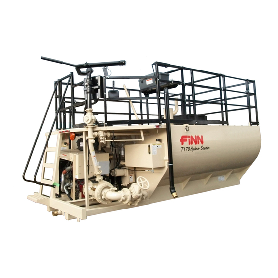
T170 HydroSeeder
Model MB
Serial No. _____________
Activate
Activate
Your Warranty
Your Warranty
By Registering
By Registering
TODAY!!!
TODAY!!!
®
Advertisement
Table of Contents

Related Manuals for Finn HydroSeeder T170 MB


Summary of Contents for Finn HydroSeeder T170 MB
- Page 1 Activate Activate Your Warranty Your Warranty By Registering By Registering TODAY!!! TODAY!!! 9281 LeSaint Drive • Fairfield, Ohio 45014 Phone (513) 874-2818 • Fax (513) 874-2914 Sales: 1-800-543-7166 ® T170 HydroSeeder Operator Instructions and Parts Manual Model MB Serial No. _____________ T170 MB0521 Rev.
- Page 2 For Office Use Only Date Update Description Code 09/20/17 Initial release; Agitator Improvement MB2017 10/11/17 Hydraulic hose update MB2017 11/10/17 Revision A: Correct part number for battery (International AGM Battery); MB2017 Added Hose Protector and Swivel Adapter Fitting 05/21/18 Revision B: New Automatic Lubricator on Pump MB0521...
- Page 3 Labor hours must coincide with the published “Labor Schedule” or estimate approved by the Finn Warranty Administrator. Once work is done, a Finn Warranty Claim Form must be fi lled out and emailed along with any related receipts or invoices to the Warranty Administrator. We ask that this is done ASAP after work is completed.
-
Page 5: Table Of Contents
Lubrication and Fluids Chart ........45 Continued to next page. ® HydroSeeder is a registered trademark of the FINN Corporation... - Page 6 D. Clutch Facing Plates (Item 30) Replacement ....50 ® FINN T170 HydroSeeder Technical Specifications ....52 - 53 Parts Section.
-
Page 7: Safety First
SAFETY FIRST With any piece of equipment, new or used, the most important part of its operation is SAFETY! FINN Corporation encourages you and your employees to familiarize yourselves with your new equipment and stresses safe operation. The first five pages of this manual are a summary of the main safety aspects associated with this unit. -
Page 8: Hydroseeder ® Safety Summary Section
® HYDROSEEDER SAFETY SUMMARY SECTION It is important that operators of this machine are familiar with all safety aspects covered in this section and have read the entire Operator’s Manual before operating the machine. Always keep a copy of this manual with the machine. It is the responsibility of the operator of the machine to fully understand this safety summary section. - Page 9 3. Recirculation valve must be open and material II. MACHINE OPERATION (Continued) flowing back into the tank when using the remote valve. A closed or plugged recirculation line will 6. Operator(s) of equipment should cause extreme heat in the pump or discharge lines never ride on the machine at that will result in severe bodily injury and damage to speeds of greater than 5 mph...
- Page 10 (29 CFR 1910.147). 9. It is recommended that only authorized, genuine FINN replacement parts be used on the machine. Provide continuous ventilation or proper 10. Do not use ether cold start fluid, breathing apparatus.
- Page 11 COMMON SAFETY DECALS Hazard / Electrical Hearing Attention Shock Hazard Hazard Arc Flash Hazard or Electrocution Fire Hazard Explosion Hazard Hazard Body Electrostatic Fumes / Dust Entanglement Discharge Hazard Hazard Hazard Electrostatic Pinch Point / Burn Hazard Sensitive Area Entanglement Hazard Hazard Carbon...
- Page 12 COMMON SAFETY DECALS Vision Heavy Object Skin Puncture Protection Hazard Hazard Required Hearing Hot Surface Splash / Spray Protection Hazard Hazard Required Vision, Hearing Loose Clothing Stumble and Head Entanglement Hazard Protection Hazard Required Breathing, Pinch Point / Vision, Hearing Moving Belt Trip Hazard and Head...
- Page 13 COMMON SAFETY DECALS Do Not Ride Do Not Do Not on Moving Remove Obstruct Vehicle Guards or Block Do Not Spray Do Not Do Not Touch Power Lines Pressure Wash Additional SAFETY Decals...
-
Page 14: Operation And Maintenance
OPERATION AND MAINTENANCE MANUAL ® FOR FINN T170 HYDROSEEDERS This manual provides instructions for the operation and maintenance of the FINN T170 ® HydroSeeder . For best results and to ensure longer life of the equipment, please follow these instructions carefully. For your safety, read the entire manual before operating this unit. -
Page 15: General Mounting Guidelines
® Mounting the HydroSeeder to the truck must allow for tire clearance and frame twist. Place hard wood spacers along the length of truck rails or use FINN spring mounting kit (part number 011562) or equivalent. -
Page 16: Attachments
ATTACHMENTS 1. Extension hoses for reaching remote areas are available in 50 ft. (15 m), 100 ft. (30.5 m), and 200 ft. (61 m) lengths. All connections are camlock quick-operating fittings. The hose is connected to the end of the discharge boom in place of a nozzle. The nozzle is connected to the end of the hose and controlled by the person on the ground. -
Page 17: Equipment Check
EQUIPMENT CHECK Equipment check should be made with the engine OFF and all rotating parts stopped. Failure to comply could result in severe personal injury or death. 1. Make sure that tool kit contains all the prescribed items. See TOOL KIT list in parts section. -
Page 18: Two-Valve Operation
TWO-VALVE OPERATION ® This HydroSeeder is equipped with two independently operated ball valves to control DISCHARGE VALVE slurry flow. One is located in the recirculation line (SHOWN CLOSED) below the platform, and the other is located in the discharge line above the platform. The valve handles should be positioned as shown in Figures 4 through 6 for the particular application required. -
Page 19: Extension Hose Or Hose Reel Through Remote Port
3. EXTENSION HOSE OR HOSE REEL THROUGH REMOTE PORT: Flow is through the open recirculation valve with no flow through the closed boom discharge valve (Figure 6). Flow through the hoses is started and stopped by engaging or disengaging the slurry pump clutch. - Page 20 CONTROL BOX ® The FINN T170 HydroSeeder control box is the operation point for the unit. The control box and corresponding control box icons are illustrated below. P/N 008865 Figure 3 – Control Box Assembly ON Symbol RUN Symbol Toggle switch flipped up to the ON Key switch is in the RUN position while position to activate components.
-
Page 21: Control Panel Guide
CONTROL PANEL GUIDE NOTE: This information is to explain the function and use of the control panel when starting the unit. DO NOT start the unit at this point. Refer to STARTING PROCEDURE section for actual operation. SYSTEM POWER UP The control panel is powered from the engine battery connection from the engine harness connector. - Page 22 EMERGENCY STOP EMERGENCY STOP EQUIPMENT A critical safety component of this equipment is the Emergency Stop (E-Stop) switch. This device is located next to the control panel, and the button is colored red to be visible and to indicate a "stop" function based on color association.
- Page 23 CONTROL PANEL GUIDE AND SYSTEM OPERATION MENU NAVIGATION The control unit has three Engine Data Alarm navigation buttons which are Symbol Indicator configured as softkeys. The system softkeys are used to navigate between displays, select menu items and change Engine data.
- Page 24 CONTROL PANEL GUIDE AND SYSTEM OPERATION (CONTINUED) MAIN MENU ACCESS To access the Main Menu, press any of the three navigation buttons. The unit will display a softkey popup window defining the available navigation possibilities. Select the Main Menu using the center softkey as shown.
- Page 25 FAULT CODES Engine fault codes (active and stored) are generated by the engine ECU and communicated to the control panel. ACTIVE FAULT CODES The control system reads standard messages to indicate active fault codes. When a fault is active the control system activates a popup fault display containing a check engine icon, fault code number (if applicable),...
- Page 26 FAULT CODES (CONTINUED) STORED FAULT CODES The control unit allows the operator to request any stored fault codes that may be contained in the engine ECU. To view stored faults select the “Fault Codes” menu selection from the main menu. The control system will send a request to the engine ECU for any faults that the ECU may have stored.
- Page 27 RESETTING MAINTENANCE TIMER The maintenance timer is operator configurable and can be accessed through the engine settings menu. See “Reset MaintTimer” selection in engine settings menu. When the maintenance timer has expired, a pop-up alert window indicating that “Engine Maintenance is Due” will be displayed.
- Page 28 CONTRAST SETTING The LCD contrast is adjustable from 0 to 100%. To adjust the LCD contrast enter the Main Menu and navigate to the “Display Setup” menu using the “ ” softkey. When highlighted enter the Display Setup menu by selecting the “ ” softkey.
- Page 29 DISPLAY MODE SETTING Two display formats are available: “Single” display and “Dual” display formats. To access the display format setting, enter the Main Menu. Navigate to the “Display Setup” menu entry using “ ” softkey. When highlighted, enter the Display Setup menu by selecting the “...
- Page 30 DISPLAY LIST SINGLE DATA FORMAT DUAL DATA FORMAT...
- Page 31 ABOUT MENU The About Menu indicates the software information used for programming the control unit. ENGINE SETTINGS The Engine Settings are factory-specified. This feature is password-protected to ensure the correct use of the engine in this unit.
-
Page 32: Starting Procedure
® The following tables show loading versus coverage rates for the FINN T170 HydroSeeder Table A shows rates for one-step applications. The coverage area is determined by the fiber ®... - Page 33 TABLE A Using Seed, Fertilizer, and Mulch Unit Amount of Material in Tank in pounds (kilograms) Coverage Area Seed Fertilizer Mulch sq. ft. (sq. m) T170 172 (78) 200 (91) 750 (340) 21,780 (2,023) Table is based on 1,500 lbs. (680 kg) of mulch, 400 lbs. (181 kg) of fertilizer and 345 lbs. (156 kg) of seed at 8 lb (3.6 kg) / 1,000 sq.
- Page 34 Top of Load Hatch 1,750 Gallons 6,624 Liters Bottom T170 Gallons in. (cm) From in. (cm) From Top (Liters) of Load Hatch Bottom 1,700 (6,435) 9.5 (24.1) 49.25 (125.1) 1,600 (6,057) 12 (30.5) 46.75 (118.7) 44.5 (113) 1,500 (5,678) 14.25 (36.2) 1,400 (5,300) 16.5 (42) 42.25 (107.3)
-
Page 35: Loading
(turn off) the slurry pump clutch. G. Replace nozzle and gasket in discharge boom. 5. Continue filling tank with water. 6. Increase engine speed to full RPM. Governed speed of the engine on the FINN T170 HydroSeeder® should be 2,500 RPM under load. - Page 36 LOADING (FOR WOOD FIBER MULCH, IF LIMING SEE LIMING WITH ® THE HYDROSEEDER SECTION) - CONTINUED 7. Start loading dry material, loading the lightest material first. Agitator control should be in full REVERSE for mixing. A. Seed – Cut open the seed bag open and dump contents into slurry tank. (When using inoculant, add it in the tank along with the seed.) When using quick swelling seeds, load them just prior to application.
- Page 37 G. Replace coupler gasket in the remote valve coupler or in boom. 5. Continue filling tank with water. 6. Increase engine speed to full RPM. Governed speed of the engine on the FINN T170 HydroSeeder® should be 2,500 RPM under load.
- Page 38 LOADING AND MIXING BFM, FGM, SMM AND OTHER HIGHLY VISCOUS SLURRIES (CONTINUED) 7. Start loading dry material, loading the lightest materials first. Agitator control should be in full REVERSE for mixing. Seed - Cut open the seed bag and dump contents into slurry tank. (When using inoculant, add it in the tank along with the seed.) When using quick-swelling seeds, load them just prior to application.
-
Page 39: Prior To Application
PRIOR TO APPLICATION 1. Operator(s) should familiarize themselves with the area to be seeded and develop a plan to ensure uniform application. 2. Develop a plan for communication between operator and driver of the carrying or towing vehicle to signal for start, stop, turn, etc., through the use of the signal horn. 3. -
Page 40: Discharge Through The Boom
APPLICATION OF SLURRY (CONTINUED) 3. Application of wood and paper fiber: Whenever possible, aim the stream towards the ground to create a surface with small pockmarks which will help get seed in contact with ground. Do not allow the stream to blast away the surface of the seed bed. 4. -
Page 41: Extension Hose System Without Remote Valve
APPLICATION OF SLURRY (CONTINUED) 4. When finished spraying, close the remote valve, disengage (turn off) the slurry pump clutch, and stop the engine. If using fiber mulch, retain as much water as possible in the hose by elevating the hose ends or by coupling the hose ends together. 5. -
Page 42: Liming With The Hydroseeder
This keeps the solids from settling in the lines, and creating a clog. This unit was designed for the application of agricultural-grade lime or FINN-HLL liquid lime only. PROCEDURE 1. -
Page 43: Troubleshooting Your Hydroseeder
® LIMING WITH THE HYDROSEEDER (CONTINUED) 15. With the slurry pump clutch still engaged (turned on), re-open discharge valve to commence application. To decrease pump wear and increase discharge distance, it may, at this point be desirable to close the recirculation valve. However, the recirculation valve must be open BEFORE closing the discharge valve if the application of slurry is to be interrupted. - Page 44 ® TROUBLESHOOTING YOUR HYDROSEEDER (CONTINUED) Before loosening any clamps, determine if the pipe is hot. If so, let it cool before attempting to perform repair. Failure to comply WILL result in severe personal injury or death. B. If the recirculation system is not working: a) Disengage (turn off) the slurry pump clutch and shut down engine.
- Page 45 Troubleshooting Chart Symptom Probable Cause Suggested Solutions LEAKS Tank Bearing Lack of lubrication - seal worn. Replace seal and follow lube schedule. Bolts not tightened. Tighten uniformly to 25 lb-ft (34 N•m). Pressure Pipe Clamps Rubber seal cracked, pinched, Replace, always grease seal torn or missing.
- Page 46 Troubleshooting Chart Symptom Probable Cause Suggested Solutions VALVE Valve stuck Frozen Thaw out ice and lubricate valves; leave valves in the open position during storage. Constant plugging Foreign material in slurry. Drain and clean out tank; check during operation sump area for foreign materials. ®...
-
Page 47: Hydraulic System
The hydraulic oil filter must be replaced on schedule with a 5 micron absolute filter (FINN part number 008703). The hydraulic system relief is factory-set at 2,650 psi (18,271 kPa). -
Page 48: Cleaning And Maintenance
CLEANING AND MAINTENANCE AFTER FIRST 4 TO 8 HOURS OF OPERATION Check and adjust clutch. See CLUTCH MAINTENANCE section. DAILY ® 1. Cleaning the HydroSeeder A. Fill slurry tank to center of agitator shaft with clean water. B. Move agitator lever to full speed (FORWARD and REVERSE) to flush off inside of tank top and walls. -
Page 49: Weekly Or Every 40 Hours Of Operation
CLEANING AND MAINTENANCE (CONTINUED) D. Lubricate the swivel on the discharge boom assembly and the swivel on the hose reel. E. If equipped with the Air Flush Option, refer to the Air Flush System Manual. F. Check the level in the hydraulic oil reservoir; maintain level with the sight gauge. WEEKLY OR EVERY 40 HOURS OF OPERATION 1. - Page 50 Figure 9 – Lubrication and Adjustment Points...
-
Page 51: Lubrication And Fluids Chart
CL Chassis Lubricant WEEKLY (40 Hours) MO Motor Oil – See Engine Manual EACH LOAD HO Hydraulic Oil, Finn Vulhydra or equivalent SEASONALLY (500 Hours) ISO grade oil (See Hydraulic System section SEE ENGINE MANUAL for ISO grade oil selection) -
Page 52: Factory Tolerances
CLUTCH/PUMP COMBINATION (CLUMP) MAINTENANCE NOTE: Refer to Figures 10 for all in-text callouts mentioned. Clump maintenance should be done only while engine is not running and battery cables are disconnected. Failure to comply could result in minor or moderate personal injury. Failure to comply could also result in product or property damage. -
Page 53: Impeller Clearance
PUMP MAINTENANCE SECTION (CONTINUED) B. IMPELLER CLEARANCE – To bring the pump back to proper tolerance, proceed as follows: 1. Loosen four bolts (1B), and push pump suction cover (1) into pump casing (5) until pump suction cover touches the pump impeller (3). Pump impeller should be in full contact with pump suction cover. -
Page 54: Clutch Maintenance Section
PUMP MAINTENANCE SECTION (CONTINUED) 3. Install the seal spring on the hub of pump impeller. After coating the threads on pump shaft with an anti-seize compound, install pump impeller and seat it securely. 4. Utilizing O-ring (2), reinstall suction cover using eight bolts (5B). At this time, check to see that pump runs freely. -
Page 55: Lubrication
CLUTCH MAINTENANCE SECTION (CONTINUED) HANDLE PRESSURE Variation in handle length directly affects the required handle pressure needed for clutch adjustment. See the table below to determine the correct handle pressure. Reference Pressure Clutch Size Lever Length at Lever 10 in. 7-5/8 in. -
Page 56: Clutch Facing Plates (Item 30) Replacement
CLUTCH MAINTENANCE SECTION (CONTINUED) D. CLUTCH FACING PLATES (ITEM 30) REPLACEMENT A common indication that the facing's friction surface is worn out is that the adjusting ring cannot be turned any tighter. To replace the facing plates, remove the slurry clutch pump from the engine as described above and proceed as follows: 1. - Page 57 THIS PAGE LEFT BLANK INTENTIONALLY...
- Page 58 16 ft. 8 in. (508 cm) 7 ft. 9 in. (236 cm) 8 ft. 10 in. (269 cm)
-
Page 59: Finn T170 Hydroseeder Technical Specifications
® FINN T170 HYDROSEEDER TECHNICAL SPECIFICATIONS POWER ..........Cummins QSF 2.8 L Diesel, Tier 4F, 65 hp (48kW) with Vibration isolation. Controls include: over-center clutch, agitator direction and speed, discharge boom and recirculation control valves, engine throttle, safety horn and engine start/stop ENGINE SAFETY SYSTEM ....Low oil pressure, Electronic Engine Control and Monitoring... - Page 60 THIS PAGE LEFT BLANK INTENTIONALLY...
-
Page 61: Parts Section
® T170 HydroSeeder Parts Section Model MB WHEN ORDERING PARTS, BE SURE TO STATE SERIAL NUMBER OF MACHINE T170 MB0521 Rev. B... - Page 62 WHEN ORDERING PARTS, BE SURE TO STATE SERIAL NUMBER OF MACHINE T170 MB0521 Rev. B...
-
Page 63: Structure And Railing
FUEL TANK POLY HATCH DETAIL DETAIL STRUCTURE AND RAILING Ref. Part Number Description No. Req’d 013149 Swing Gate 013122 Gate Spring F330-0108 Main Tank Top F170-0015 Left Side Toe Rail 008639 Left Side Guard Rail F330-0120 Front Tank Top Support 012703 Slide Gate 012737... - Page 64 STRUCTURE AND RAILING Ref. Part Number Description No. Req’d F330-0084 Rear Corner Toe Rail 002191 2-1/2 in. Male Brass Adapter 002190 Dust Cap with Gasket - Main Tank Drain 006513 Dust Cap Gasket 190018 2 in. Wide Conformable Safety Walk 6 ft.
- Page 65 THIS PAGE LEFT BLANK INTENTIONALLY WHEN ORDERING PARTS, BE SURE TO STATE SERIAL NUMBER OF MACHINE T170 MB0521 Rev. B...
- Page 66 WHEN ORDERING PARTS, BE SURE TO STATE SERIAL NUMBER OF MACHINE T170 MB0521 Rev. B...
-
Page 67: Discharge Boom Assembly
DISCHARGE BOOM ASSEMBLY Ref. No. Ref. Part Number Description No. Req’d 012763 Lower Boom Discharge Weldment 012283 2-1/2 in. Straight Swivel 012762 Upper Boom Discharge Weldment 013159 Boom Discharge Handle Weldment 012726-01 Boom Stand Pipe 010544 2-1/2 in. Female Coupler 006513 2-1/2 in. - Page 68 WHEN ORDERING PARTS, BE SURE TO STATE SERIAL NUMBER OF MACHINE T170 MB0521 Rev. B...
-
Page 69: Engine
ENGINE Ref. No. Part Number Description No. Req’d 075880 QSF 2.8 Engine ------ Engine ECM (Supplied with Engine) 008768 ECM Mounting Isolators 008735 Rear Left Engine Foot 008737 Front Left Engine Foot 008762 Hydraulic Pump 008758 Upper Radiator Support 023438 Radiator Isolator 008757 Upper Radiator Support Bracket... - Page 70 ENGINE Ref. No. Part Number Description No. Req’d 008755 Radiator Fan Spacer M10 x 110 Gr. 10.9 Hex Head Bolts 008763 Radiator 075205 Radiator Isolators 055505 Snubbing Washer 008809 Engine Oil Canister Element 008808 120 V Alternator 008830 QSF 2.8 Fan Belt 008854 Oil Dipstick and Guide Assembly 008854-01...
- Page 71 THIS PAGE LEFT BLANK INTENTIONALLY WHEN ORDERING PARTS, BE SURE TO STATE SERIAL NUMBER OF MACHINE T170 MB0521 Rev. B...
- Page 72 WHEN ORDERING PARTS, BE SURE TO STATE SERIAL NUMBER OF MACHINE T170 MB0521 Rev. B...
-
Page 73: Engine Sheet Metal
ENGINE SHEET METAL Ref. Part Number Description No. Req’d 008664 Rear Sheetmetal Mount Leg (Long) 008784 Sheetmetal Support Bracket 008740 Rear Sheetmetal Cover 008742 Top Sheetmetal Cover 055669 Door Positioning Hinge F260-0006-03 Hinge Spacer F260-0006-02 Radiator Cap Cover 008745 Rear Sheetmetal Mount Leg (Short) F170-0026 Radiator Cover Mount Bracket F170-0020... - Page 74 17 18 15 16 Primary Filter Element Secondary Filter Element WHEN ORDERING PARTS, BE SURE TO STATE SERIAL NUMBER OF MACHINE T170 MB0521 Rev. B...
-
Page 75: Air Intake And Exhaust Systems
AIR INTAKE AND EXHAUST SYSTEM Ref. Part Number Description No. Req’d 012991 Rain Cap Assembly 023471 Exhaust Elbow 055501 Muffler Clamp 008752 Exhaust Pipe Extension 008759 DOC Muffler 008796 Muffler Mounting Bracket 008829 Muffler Mounting Bracket Band 008798 DOC Mounting Plate 008797 DOC Hanger 008804... - Page 76 SECTION A-A WHEN ORDERING PARTS, BE SURE TO STATE SERIAL NUMBER OF MACHINE T170 MB0521 Rev. B...
-
Page 77: Control Station And Control Box
CONTROL STATION AND CONTROL BOX Ref. No. Ref. Part Number Description No. Req’d F170-0029 Guard Rail Control Box Mounting Bracket 008800 Control Box Mounting Plate 012970 Emergency Stop (E-stop) with Enclosure 008801 Control Box Cover 008802 Control Box Cover Plexiglass 055669 Door Positioning Hinge 031583... - Page 78 SECTION A-A WHEN ORDERING PARTS, BE SURE TO STATE SERIAL NUMBER OF MACHINE T170 MB0521 Rev. B...
-
Page 79: Engine Relay Box
ENGINE RELAY BOX Ref. No. Ref. Part Number Description No. Req’d 075888-01 Relay Box Enclosure 075892 Relay Box Back Panel 008838 Fuse Box 008839 Mega 250A Fuse 008840 Ametek Switch 075893 Starter Relay 080303 Cord Grip 170088 1/2 in. NPT Conduit Locknut 1 per 008857 Relay Box Harness... - Page 80 REFERENCE CLUMP ASSEMBLY WHEN ORDERING PARTS, BE SURE TO STATE SERIAL NUMBER OF MACHINE T170 MB0521 Rev. B...
-
Page 81: Clump, Piping And Discharge Assembly
CLUMP, PIPING AND DISCHARGE ASSEMBLY Ref. Part Number Description No. Req’d 011736 5 in. Victaulic Pipe Clamp 011919 5 in. Victaulic Pipe Clamp Seal 1 per 008259 5 in. 90º Pipe Elbow 011882 2-1/2 in. Toe-Goe Pipe 012722 Suction Valve Flange Weldment 012058 5 in. - Page 82 WHEN ORDERING PARTS, BE SURE TO STATE SERIAL NUMBER OF MACHINE T170 MB0521 Rev. B...
-
Page 83: Clutch / Pump (Clump) Assembly
CLUTCH / PUMP (CLUMP) ASSEMBLY Ref. No. Ref. Part Number Description No. Req’d 005146 Pump Suction Cover 005150 O-ring 005145 Pump Impeller 006443 Mechanical Shaft Seal 005144 Pump Casing 006444 Grease Retainer 005446 Flange Pilot Bearing 012733 Grease Retainer Seal 012734 Bearing Retainer Ring 012729... - Page 84 CLUTCH / PUMP (CLUMP) ASSEMBLY Ref. No. Ref. Part Number Description No. Req’d 012783-02 Lock Washer 012783-01 Drive Shaft Nut 190123-24 Clutch Key 100024 Adjusting Lock 002383 Automatic Pressure Lubricator NOT SHOWN Lock Bolt for Adjustment Lock Lock Washer for Adjustment Lock 160389 3/8 in.
- Page 85 THIS PAGE LEFT BLANK INTENTIONALLY WHEN ORDERING PARTS, BE SURE TO STATE SERIAL NUMBER OF MACHINE T170 MB0521 Rev. B...
- Page 86 DETAIL A WHEN ORDERING PARTS, BE SURE TO STATE SERIAL NUMBER OF MACHINE T170 MB0521 Rev. B...
-
Page 87: Controls
CONTROLS Ref. Part Number Description No. Req’d 008672 Agitator Control Handle 008673 Agitator Handle Pivot 022202 Black Handle Grip 085148 2-1/2 in. U-Bolt 005161 Rubber Strap with "S" Hooks 004996 Pipe Plug 012777 Recirculation Handle F330-0102 Agitator Control Box 012780-05 Recirculation Valve Rod Weldment 006737 Ball Joint... - Page 88 BEARING ASSEMBLY 2 in. AGITATOR NOTE: BEARING ASSEMBLY (012529) SHAFT THROUGH BACK SIDE APPLY (1) SOLID, CONTINUOUS BEAD OF SILICONE ADHESIVE AROUND OUTER EDGE ON THE INSIDE FACE OF THE CLAMPING RING BEFORE INSTALLATION. OUTSIDE OF TANK WALL NOTE: TO TIGHTEN, TURN NUT - NOT THE BOLT. TORQUE TO 25 lb-ft (34 N•m).
-
Page 89: Agitator And Bearing Assemblies
AGITATOR AND BEARING ASSEMBLIES Ref. No. Ref. Part Number Description No. Req’d 012527 Agitator Clamping Ring 1 per 012528 Agitator Shaft Seal 2 per 012525 Agitator Bearing Clamping Ring 1 per 012452 Flangette 1 per 012450 Bearing 1 per 012451 Flangette with Lube Coupling 1 per 008154... - Page 90 WHEN ORDERING PARTS, BE SURE TO STATE SERIAL NUMBER OF MACHINE T170 MB0521 Rev. B...
-
Page 91: Hydraulic System
HYDRAULIC SYSTEM Ref. No. Ref. Part Number Description No. Req’d 008545 1 in. FNPT - #20 MSAE Adapter 008845 1-1/4 in. MNPT - #20 MJIC 90° Elbow Adapter 008606 #16 MSAE - #8 MJIC Adapter 008660 1/2 in. MNPT - #4 MJIC Adapter 008689 #8 MSAE - # 8 MJIC Tee 008690... - Page 92 HYDRAULIC SYSTEM Ref. No. Ref. Part Number Description No. Req’d 080329 Hydraulic Level Sight Gauge 160236 1/2 in. Pipe Plug 160520 1-1/4 in. Nipple x 4-1/2 in. Long 085157 #12 MSAE - #12 MJIC 45° Elbow Adapter 085276 Dump Valve 085276-01 Dump Valve Coil 085276-02...
-
Page 93: Hydraulic Agitator Drive
REFERENCE the AGITATOR and BEARING ASSEMBLIES HYDRAULIC AGITATOR DRIVE Ref. Part Number Description No. Req’d 012333 Hydraulic Motor 012354 Hydraulic Motor Mount F330-0029 Agitator Coupling Guard 012522-02 Rubber Bushing 012522-04 Torque Arm Insert 011780 Rigid Coupling 003055B Motor Bushing 055103 Agitator Bushing 190127-40 1/2 in. -
Page 94: Discharge Hose Extensions
DISCHARGE HOSE EXTENSIONS BOOM TAKE OFF SYSTEM Part Number Description No. Req’d 007930-02 Boom Discharge Extension Hose Assembly As Ordered 008315-05 1-1/2 in. x 50 ft. Extension Hose with Nipples 002191 2-1/2 in. Male Brass Adapter 160768 2-1/2 x 1-1/2 in. Reducer Bushing 010544 2-1/2 in. - Page 95 DISCHARGE HOSE EXTENSIONS HOSE REEL SYSTEM Part Number Description No. Req’d 061359 1-1/4 in. Hose Reel Discharge Hose As Ordered 004832-20 1-1/4 in. x 200 ft. Rubber Hose with Nipples 002158 1-1/2 in. Female Coupler 006515 1-1/2 in. Coupler Gasket 160756 1-1/2 x 1-1/4 in.
- Page 96 DETAIL A DETAIL A WHEN ORDERING PARTS, BE SURE TO STATE SERIAL NUMBER OF MACHINE T170 MB0521 Rev. B...
-
Page 97: Hose Reel Assembly
HOSE REEL ASSEMBLY Ref. No. Ref. Part Number Description No. Req’d 080302 Flanged Riser 080302G Hose Reel Riser Gasket 008144 Hose Reel Gear 008200 Hose Reel Chain (69 in.) 008433 Pinlock with Brackets Assembly 008313 Idle Side Bearing 008111B Brake Assembly 008314 Drive Side Bearing 008199... - Page 98 DETAIL A DETAIL A WHEN ORDERING PARTS, BE SURE TO STATE SERIAL NUMBER OF MACHINE T170 MB0521 Rev. B...
- Page 99 HOSE REEL ASSEMBLY Ref. No. Ref. Part Number Description No. Req’d 008112 Brake Spring (Part of Hose Reel) 008109 Brake Adjustment Screw (Part of Hose Reel) NOT SHOWN 1-1/4 in. Hose Option 004832-20 1-1/4 in. Hose Reel Hose x 200 ft. A2073-001 Hose Protector A2071-001...
- Page 100 To Dump Valve To Brand Valve WHEN ORDERING PARTS, BE SURE TO STATE SERIAL NUMBER OF MACHINE T170 MB0521 Rev. B...
-
Page 101: Hose Reel Hydraulic System
HOSE REEL HYDRAULIC SYSTEM Ref. No. Ref. Part Number Description No. Req’d 008693-01 1/2 in. Hydraulic Hose x 179 in. 008693-02 1/4 in. Hydraulic Hose x 23 in. 008693-03 1/2 in. Hydraulic Hose x 134 in. 008693-04 1/4 in. Hydraulic Hose x 70 in. 008639-05 1/4 in. -
Page 102: Recommended Spare Parts And Repair Kits
RECOMMENDED SPARE PARTS AND REPAIR KITS RECOMMENDED SPARE PARTS Part Number Description No. Req’d A2401-001 Automatic Pressure Lubricator Grease, 14 oz. (414 mL) 011919 Suction Pipe Seal - 5 in. 008472 Suction Pipe Seal - 5 in. x 4 in. Reducer 002820 Discharge Pipe Seal - 2-1/2 in. -
Page 103: Tool Kit
Automatic Pressure Lubricator Grease, 14 oz. (414 mL) 020365 Multi-Purpose Grease Cartridge 007469 Lube Sticks For Discharge and Recirculation Valves (Box of 24) 012681A Touch-Up Paint (FINN Beige - Aerosol) 012305 Remove Aerosol Can Adhesive Label Engine Operator's Manual ® HydroSeeder... - Page 104 WHEN ORDERING PARTS, BE SURE TO STATE SERIAL NUMBER OF MACHINE T170 MB0521 Rev. B...
-
Page 105: Decals
DECALS Ref. No. Ref. Part Number Description No. Req’d 023174 "FINN" Decal ® 011595 "HydroSeeder " Decal --------- "WARNING! Fall Hazard" Decal --------- "1,500 Gallon" Decal --------- "1,000 Gallon" Decal --------- "800 Gallon" Decal --------- "500 Gallon" Decal --------- "Service Daily" (Up Arrow) Decal... - Page 106 DECALS Ref. No. Ref. Part Number Description No. Req’d --------- Attention Decal --------- Read Manual Decal --------- "Throttle" Decal --------- "Pump ON / OFF" Decal --------- "Emergency Stop" Decal --------- Key Switch Decal --------- "DIESEL FUEL" Decal --------- Decibel Decal --------- "Drain Water Daily"...
Need help?
Do you have a question about the HydroSeeder T170 MB and is the answer not in the manual?
Questions and answers