
Related Manuals for Finn II HydroSeeder T90


Summary of Contents for Finn II HydroSeeder T90
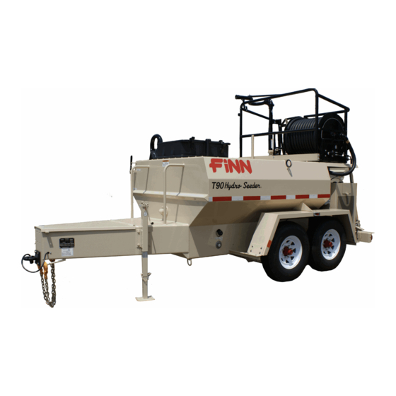
- Page 1 9281 LeSaint Drive • Fairfield, Ohio 45014 Phone (513) 874-2818 • Fax (513) 874-2914 Parts Dept.: 1-800-229-8707 Sales: 1-800-543-7166 ® ® T90/120 II HydroSeeder Parts and Operator’s Manual Model SS Serial No. _____________ LBT90-SS...
- Page 2 BLANK...
-
Page 3: Table Of Contents
T120 Series II Gooseneck Assembly ......54-55 ® HydroSeeder is a registered trademark of Finn Corporation... - Page 4 Skid Parts ...........56 Hatch Assembly .
-
Page 5: Safety First
SAFETY FIRST With any piece of equipment, new or used, the most important part of its operation is SAFETY! Finn Corporation encourages you and your employees to familiarize yourselves with your new equipment and to stress safe operation. The first four pages of this manual are a summary of all the main safety aspects associated with this unit. -
Page 6: Safety Summary Section
Practice all other usual and customary safe working precautions; and above all, remember that safety is up to you. The FINN HydroSeeder ® is designed to mix and apply water, seed, fertilizer, agricultural lime and hydraulic mulch to the prepared seedbed. The resultant slurry from mixing one or more of the above materials may react causing harmful or deadly gasses within the tank. - Page 7 5. The driver of the carrying or towing vehicle is respon- 2. Never engage the clutch sible for the safety of the operator(s) of the machine. when both the recirculation Make sure the driver is aware and avoids all possible and discharge valves are hazards to the operator(s) of the machine, such as low closed.
- Page 8 Make sure your company’s plan meets all the requirements of 29 CFR 1910.146. including the following: 9. It is recommended that only authorized genuine FINN a) Drain, flush and ventilate tank interior. replacement parts be used on the machine.
- Page 9 CURRENT SET OF SAFETY DECALS Before entering the tank: 1. Drain, flush and ventilate tank interior. 2. Turn off engine and disconnect battery cables. 3. Provide continuous ventilation or proper breathing apparatus. 4. Provide standby individual outside of tank able to communicate Never operate pump with with person inside and able to haul Do not aim stream...
-
Page 10: Definition Of Hydroseeding
FINN T90 & T120 HYDROSEEDERS ® This manual gives you step by step instructions for the operation and maintenance of the Finn HydroSeeder For best results and to insure longer life of the equipment, please follow the instructions carefully. For your safety read the entire manual before operation of this unit. -
Page 11: Mounting
Mounting the HydroSeeder to the truck must allow for tire clear- ance as well as frame twist. Place hard wood spacers along the length of truck rails or use Finn spring mounting kit (#011562) or equivalent. ® C. Place chains over the HydroSeeder and around truck bed and secure with binders. -
Page 12: Pre Start Check
4. Fill pumps with the capacity of 5,500 GPH (19,000 l/h) or 9,000 GPH (34,000 l/h) can either be ® carried on the truck or mounted on the HydroSeeder 5. Hardened pump parts. Pump casing, impeller, and suction cover treated with special material designed to resist wear. - Page 13 Turn thumb nut clockwise until stem rises to maximum height. b) Remove cap and fill cap with sodium (water soluble) base grease. (FINN part number 000698). Do not use lithium base (chassis lube) grease. c) Replace cap.
-
Page 14: Valve Operation
TWO VALVE OPERATION: ® This HydroSeeder is equipped with two independently operated ball valves to control slurry flow. One is located in the recirculation line below the platform, and the other is located in the discharge line above the platform. The recirculation valve is open when the handle is in line with the valve ports and is closed when the handle is at a right angle to the valve ports. - Page 15 1. Discharge Through Boom: Flow is through boom with no flow through closed recirculation valve (Figure 2). Flow through boom is controlled by engaging and disengaging slurry pump clutch. Do not use the discharge valve to control distance. Valve should be either completely open or complete- ly closed.
-
Page 16: Starting Procedure
® The following tables show loading versus coverage rates for the Finn HydroSeeder . Table A shows rates for ®... - Page 17 TABLE A Using Seed, Fertilizer and Mulch Unit Amount of Material in Tank (pounds(kilograms)) Coverage Area (sq. ft.(sq. m.)) Seed Fertilizer Mulch T90 II 92 (41) 107 (48.5) 400 (181) 11,600 (1075) T120 II 115 (52) 133 (60) 500 (227) 14,520 (1350) Above Table is based on 1500 pounds of mulch, 400 pounds of fertilizer and 345 pounds of seed (8 pounds/1000 square feet) per acre.
-
Page 18: Tank Capacity Chart
TANK CAPACITIES CHART: T90 II Gallons in. (cm) from in. (cm) from (Liters) bottom 900 (3407) 10 (25.4) 42 (106.7) 850 (3207) 12 (30.5) 40 (101.6) 800 (3028) 13.75 (34.9) 38.25 (97.2) 750 (2839) 15.75 (40.00) 36.25 (92.1) 700 (2650) 17.5 (44.4) 34.25 (87.6) 650 (2460) -
Page 19: Loading
LOADING (For wood fiber mulch, if liming see page 19): CAUTION: Take care not to lose pens, lighters, etc. from shirt pockets or drop pieces of paper or plastic bags into the tank, as these might plug the slurry system. 1. -
Page 20: Prior To Application
C. Fertilizer - Stand over hatch opening and drop the bag onto the bagcutter. Grasp both ends of the bag and dump material. D. All other additives - Consult with manufacturer for proper loading technique. 7. When all materials are loaded and in suspension, and the tank is full, move the agitator to neutral then full speed forward to insure all material is mixed. -
Page 21: Application Of Slurry
APPLICATION OF SLURRY: I. General Application Techniques DANGER: Do not spray toward power lines, transformers or other high voltage conductors. CAUTION: The driver of the carrying vehicle should remain alert for hazards to the operator, such as low power lines, hanging branches, etc. -
Page 22: Application Through Hoses
A. PUMP TAKE OFF SYSTEM OR HOSE REEL WITH REMOTE VALVE : 1. Open recirculation valve and close discharge valve and close remote valve at the end of the hose. 2. Engage clutch. When stream is flowing freely through the recirculation line, open the pump take off valve. -
Page 23: Reloading
RELOADING PROCEDURE: 1. Start at step 2 in loading procedure on page 15. 2. After last load of the day refer to the cleaning and maintenance section of the manual on pages 20-21. ® LIMING WITH THE HydroSeeder ® In using large concentrations of granular solids through the HydroSeeder , it is advisable to keep the slurry moving through the pump at all times. -
Page 24: Cleaning And Maintenance
CAUTION: To decrease pump wear and increase discharge distance, it may now be desirable to close the recirculation valve. However, the recirculation valve must be open BEFORE closing the discharge valve if the application of slurry is to be interrupted. Extreme heat, which will cause damage and/or bodily injury, will occur if both valves are closed. -
Page 25: Hydraulic System
The hydraulic oil filter must be replaced on schedule with a 10 micron filter - Finn part #021618. The hydraulic system relief is factory set at 2000 psi. -
Page 26: Lubrication Chart
Figure 4... - Page 27 LUBRICATION AND FLUIDS CHART (Reference Figure 4) Ref. No. Location Lubricant Frequency Number Check Grease Level in Pressure Lubricator Daily Check Clutch Lever Bearings Daily Grease Agitator Shaft Bearings Daily Grease Discharge Swivels Daily Check Engine Oil Level Daily Check Engine Oil and Filter See Engine Manual Grease Pump Bearings Weekly...
-
Page 28: Clutch/Pump Maintenance
CLUTCH/PUMP MAINTENANCE: CAUTION: Clutch/Pump maintenance to be done only while engine is not running, and battery cables are disconnected. Figure 5 Figure 6... - Page 29 CLUTCH/PUMP ASSEMBLY (Reference Figures 5 and 6) Ref. No. Part Number Description No. Req’d 005146 Suction Cover X0824SS Suction Cover Bolt Y08SS Suction Cover Nut 006437 O-Ring 005543 Impeller 006443 Mechanical Seal Assembly 005144 Pump Casing X0824SS Suction Cover Bolt W08FSS Suction Cover Washer 006444...
- Page 30 PUMP MAINTENANCE SECTION: (Reference Figures 5 and 6) CAUTION: Pump maintenance to be done only while engine is not running, and battery cables are disconnected. A. FACTORY-TOLERANCES. 1. To check pump tolerances loosen the two clamps on the pump suction piping and remove the inlet elbow.
- Page 31 D. INSTALLING NEW SEAL ASSEMBLY (#4) (Do not unwrap the new seal assembly until you are ready to install. All parts of the assembly are packed in sequence of installation.) 1. To replace the seal assembly (4), perform the above operations under cleaning and remove pump casing (5) by removing the three bolts (10B) holding the casing to the clutch housing (10).
- Page 32 B. LUBRICATION. 1. Lubricant: Use any high grade, Lithium Base #2, short fiber grease having an operating tempera- ture of 200˚ F (93˚ C), recommended for roller bearings may be used. Do not mix Sodium or Calcium base grease with Lithium grease. IMPORTANT: 2.
-
Page 33: Trouble Shooting The Hydroseeder
D. Engage the clutch by applying pressure on top of release sleeve and collar assembly (20) and lock clutch facings between the pressure plate and clutch body. If clutch facings are still free to move, disengage the clutch and turn adjusting ring COUNTER-CLOCKWISE just enough to lock the clutch facings in place when clutch is engaged. - Page 34 A. Obstruction in the discharge nozzle is determined by a change or stoppage of the spray pattern. a) Disengage clutch. b) Remove the nozzle. c) Clear the nozzle with the nozzle cleaning rod attached to the underside of the guard rail. DANGER: Severe injury can result from opening clamps when piping is hot.
- Page 35 ® TROUBLE SHOOTING YOUR HydroSeeder Problem Probable Causes Suggested Solutions LEAKS: Tank bearing Lack of lubrication - Replace seal and follow lube leaks. seal worn. schedule. Bolts not tightened. Tighten uniformly to 25 ft. lbs. properly. Pressure Clamps. Rubber seal cracked, Replace, always grease seal pinched or torn.
- Page 36 ® TROUBLE SHOOTING YOUR HydroSeeder (continued): Problem Probable Causes Suggested Solutions Suction partially plugged. Clean out machine see page 20. Nozzle worn or plugged. Clean nozzles, replace if necessary. Fertilizer. Change type. Clutch slippage. Readjust clutch page 27. VALVE: Valve stuck. Frozen.
- Page 37 ® TROUBLE SHOOTING YOUR HydroSeeder (continued): Problem Probable Causes Suggested Solutions PUMP: Excessive wear. Fertilizer with highly Change fertilizer. Avoid abrasive abrasive filler. fillers. Overloading machine with Load machine to recommended dry material. capacities. Too much time allowed After loading and mixing has been between loading and completed, set agitator at 1/2 speed discharging.
-
Page 38: Notes
NOTES... - Page 39 NOTES...
- Page 40 NOTES...
- Page 41 NOTES...
- Page 42 NOTES...
- Page 43 NOTES...
- Page 44 NOTES...
-
Page 45: Parts Manual Section
T90/120 II ® HydroSeeder Parts Manual Model SS LBT90-SS... - Page 46 WHEN ORDERING PARTS, BE SURE TO STATE SERIAL NUMBER OF MACHINE Parts Department: 1-800-229-8707 LBT90-SS...
-
Page 47: Suction, Discharge, And Recirculation Piping
SUCTION, DISCHARGE, AND RECIRCULATION PIPING Ref. No. Part Number Description No. Req’d T120 T120 005682 005682 Clutch/Pump Assembly (See pages 44-45 for parts) 002383 002383 Pressure Lubricator 005470 005470 Pump Shaft Guard 006144 006144 Pipe Clamp 006145 006145 Clamp Gasket 005699-01 006359 90˚... -
Page 48: Clutch/Pump Parts
WHEN ORDERING PARTS, BE SURE TO STATE SERIAL NUMBER OF MACHINE Parts Department: 1-800-229-8707 LBT90-SS... - Page 49 CLUTCH/PUMP ASSEMBLY Ref. No. Part Number Description No. Req’d 005682 Clutch/Pump Assembly consisting of: 005146 Suction Cover 006437 O-Ring 005543 Impeller 006443 Mechanical Seal Assembly 005144 Pump Casing 006444 Grease Retainer Seal 005446 Flange Bearing 005447 Grease Retainer Seal 005475 Bearing Retainer 005544-02 Sealing Gasket...
-
Page 50: Hydraulic Schematic
WHEN ORDERING PARTS, BE SURE TO STATE SERIAL NUMBER OF MACHINE Parts Department: 1-800-229-8707 LBT90-SS... - Page 51 HYDRAULIC SYSTEM Ref. No. Part Number Description No. Req’d 004900 Filler Breather Cap 023616 Straight Male Adapter 005551 Fill Adapter Hose 160763 Reducer Bushing 011466 Suction Strainer 160482 Pipe Nipple 021559 Ball Valve 005546 Male 90˚ Adapter Elbow 005550 Suction Hose FW71712 Straight Male Adapter 160111...
-
Page 52: Discharge Boom
DISCHARGE BOOM Ref. No. Part Number Description No. Req’d 005529 Discharge Boom Assembly Consisting of: 006102 2” Part D Coupler 006514 Gasket 005528-01 Boom Weldment Z0632SCP Boom Handle Set Screw 005528-03 Boom Collar Weldment Z0612SCP Boom Collar Set Screw 005527-05 Boom Handle 007286 Discharge Balance Spring... -
Page 53: Hydraulic Agitator Drive
HYDRAULIC AGITATOR DRIVE Ref. No. Part Number Description No. Req’d 070660 Hydraulic Motor (See page 70 for parts) X0824 1/2-13 UNC HHCS x 1-1/2 Lg. Y08L 1/2-13 UNC Lock Nut 005463 Torque Arrestor Plate 004630 Rubber Bushing 023156 Coupling Assembly X0625SH 1/2-13 UNC Socket Head x 1-1/2 Lg. - Page 54 Drive WHEN ORDERING PARTS, BE SURE TO STATE SERIAL NUMBER OF MACHINE Parts Department: 1-800-229-8707 LBT90-SS...
-
Page 55: Agitator Assembly
AGITATOR ASSEMBLY Ref. No. Part Number Description No. Req’d T120 T120 007420 007420 Bearing Assembly 007417 007417 Spacing Ring 1 per 1 per 007416 007416 Shaft Seal 1 per 1 per 007212 007212 Flangette 1 per 1 per 003022 003022 Bearing 1 per 1 per... -
Page 56: T90 Series Ii Trailer Assembly
WHEN ORDERING PARTS, BE SURE TO STATE SERIAL NUMBER OF MACHINE Parts Department: 1-800-229-8707 LBT90-SS... - Page 57 TRAILER ASSEMBLY PARTS Ref. No. Part Number Description No. Req’d T120 T120 005468 005468 Fender 005545 005545 Fender U-Bolt 005134 2-5/16” Ball Coupler 005135 2-5/16” Ball 080043 Tow Ring (Optional replaces #005134 & #005135) 005168 Safety Chain 005169 Clevis Grab Hook 005170 Chain Connector 005515-01...
-
Page 58: T120 Series Ii Gooseneck Assembly
WHEN ORDERING PARTS, BE SURE TO STATE SERIAL NUMBER OF MACHINE Parts Department: 1-800-229-8707 LBT90-SS... - Page 59 T120 GOOSENECK TRAILER ASSEMBLY Ref. No. Part Number Description No. Req’d 005600 Right Rear Guard Rail 005598 Left Rear Guard Rail 005596 Slide Gate 005599 Gooseneck Deck Rail 005617 Front Cross Rail 005698 Tool Box Mount 005619 U-Bolt 052160 Tool Box 004799 Gooseneck Coupler 004798...
-
Page 60: Skid Parts
SKID MOUNT PARTS Ref. No. Part Number Description No. Req’d 005600 Right Rear Guard Rail 005598 Left Rear Guard Rail 005596 Slide Gate 005536 Front Cross Rail 005698 Tool Box Mount 005619 U-Bolt 052160 Tool Box 005613 Square Tubing Plug WHEN ORDERING PARTS, BE SURE TO STATE SERIAL NUMBER OF MACHINE Parts Department: 1-800-229-8707... -
Page 61: Hatch Assembly
HATCH ASSEMBLY Ref. No. Part Number Description No. Req’d 005713 Hatch Assembly includes: 005486 Hatch Liner 012638 Hatch Lid 005484 Bag Cutter X0848SS 1/2-13 UNC HHCS x 3” Lg. - Stainless Steel Y08LSS 1/2-13 UNC Lock Nut - Stainless Steel W08FSS 1/2”... -
Page 62: Loose Parts
WHEN ORDERING PARTS, BE SURE TO STATE SERIAL NUMBER OF MACHINE Parts Department: 1-800-229-8707 LBT90-SS... - Page 63 COMMON LOOSE PARTS Ref. No. Part Number Description No. Req’d 005538 Right Guard Rail 005161 Rubber Strap with “S” Hook 002258 Boom Locking Handle 008454-02 Boom Clamping Strap 005528-02 Boom Holddown 005700 Pin Lanyard 031245 Snapper Pin 005540 Left Rear Guard Rail 005534-01 Left Rear Rail Strap 005536...
-
Page 64: Engine Assembly
WHEN ORDERING PARTS, BE SURE TO STATE SERIAL NUMBER OF MACHINE Parts Department: 1-800-229-8707 LBT90-SS... - Page 65 ENGINE PARTS Ref. No. Part Number Description No. Req’d 031390 Kubota V1505B-86 Engine 005682 Clutch Pump Assembly (See pages 44-45) 005679 Engine Mount 005676 Center Bushing Mount 055505 Subbing Washer 005680 Engine Top Cover 005694 Engine Cover Lid 005677 Radiator Shroud KU16665-72061 Radiator Assembly 031444 Upper Radiator Hose...
-
Page 66: Engine Wiring Diagram
16 Ga. Orange Brown Green Blue ENGINE WIRING Part Number Description No. Req’d 006499 Horn 055568 Temperature Switch 004934 Oil Switch 002256-12 Battery 031031 Battery Cable 000241 Ground Strap 080103 Fuel Pump KU16616-60010 Shutdown Solenoid 170028 Fuse with Holder 005561 Electrical Housing 023602 Electrical Housing Plug... -
Page 67: Trailer Wiring Diagram
TRAILER WIRING Ref. No. Part Number Description No. Req’d 060069 Trailer Plug 023424 Breakaway Switch 030934-01 Chain 005016 “S” Hook 005017 Snap FW71090 Amber Corner Marker Light 005434 Taillight 005435 Side Marker Light - Red 005437 3 Bar Light 005436 License Light 004720 License Light Bracket... - Page 68 WHEN ORDERING PARTS, BE SURE TO STATE SERIAL NUMBER OF MACHINE Parts Department: 1-800-229-8707 LBT90-SS...
-
Page 69: Control Box Wiring Diagram
CONTROL BOX WIRING Ref. No. Part Number Description No. Req’d 007274 Hour Meter 022119 Safety Switch KU15694-65592 Glow Plug Timer 020886 Horn Button U15403-64491 Glow Plug Indicator Light 006245 Generator Light KU66711-55131 Ignition Switch 023604 Electrical Housing 023601 Electrical Housing Plug 080304 Liquid Tight Fitting 005589... -
Page 70: Hose Reel Wiring
HOSE REEL WIRING Part Number Description No. Req’d 005691 Hose Reel Wiring Harness 008419 30 Amp Circuit Breaker 011654 40 Amp Circuit Breaker 020886 Hose Reel Button 008135 Solenoid WHEN ORDERING PARTS, BE SURE TO STATE SERIAL NUMBER OF MACHINE Parts Department: 1-800-229-8707 LBT90-SS... -
Page 71: Hose Reel
HOSE REEL Part Number Description No. Req’d 008212 Electric Hose Reel 008144 Ring Gear 008200 Chain with Connecting Link 008111 Brake Pad 008112 Brake Spring 008109 Brake Wheel 008313 Drive Side Bearing 008314 Idler Side Bearing 008433 Pin Lock Assembly with Brackets 008199 Chain Sprocket - 11 Tooth 008188... -
Page 72: Remote Valve And Discharge Hose Assembly
REMOTE VALVE AND DISCHARGE HOSE EXTENSIONS Part Number Description No. Req’d 007930 1-1/2” Semi-Rigid Hose Assembly,Boom Connection 007929 1-1/2” Hose x 50 feet Long 006102 Female Coupler 006514 Coupler Gasket 006096 Male Adapter 160763 Reducer Bushing 007930-01 1-1/2” Semi-Rigid Hose Assembly,Take-Off Connection 007929 1-1/2”... -
Page 73: Tool Kit
TOOL KIT Part Number Description No. Req’d 000698 Automatic Pressure Lubricator Grease, 1# Tub 005220 Impeller Wrench 008187 Long Distance Nozzle 006632 Long Distance Nozzle Assembly 001042 Long Distance Nozzle 006096 Brass Adapter 160309 Close Nipple 160763 Reducer Bushing 006619 Wide Ribbon Nozzle Assembly 006493 Wide Ribbon Nozzle... -
Page 74: Hydraulic Motor
Ref. No. Part Number Description No. Req’d 21618-002 Shaft and Bearing Kit 14559-006 Seal •3 9121-001 Seal, Exclusion •4 9057-009 Shaft Seal 7382-000 Ring, Back-up 21578-004 Bearing Housing • 7 9050-000 Seal, Shaft Face 22102-000 Wear Plate 21371-007 Main Drive 21625-007 Geroler 22134-000... -
Page 75: Hydraulic Valve
BRAND FLOW CONTROL VALVE SCDF SERIES All parts marked with a “•“ make up Seal Kit, Part Number 023120 AP52 Washer •SF322 O-Ring DC3705 Detent Plunger •SF323 Back Up DC7517A Shuttle Spool SF327 Cap Screw DC7548B Poppet 5/16-18 x 1-1/2” DC7550 Set Screw SF332-1... -
Page 76: Decal Location
WHEN ORDERING PARTS, BE SURE TO STATE SERIAL NUMBER OF MACHINE Parts Department: 1-800-229-8707 LBT90-SS... - Page 77 DECALS Ref. No. Part Number Description No. Req’d 011690 FINN Name Plate 023174 “FINN” Decal 011595 “HydroSeeder” Decal 005216 Decal “DANGER! OPEN RECIRCULATION” 021665 Decal “HYDRAULIC INSTRUCTIONS” 006869 Decal “PRESSURE LUBRICATOR” 020976 Decal “PATENT INFRINGEMENT” 008209 Decal “DANGER! BEFORE LOOSENING CLAMP”...
-
Page 78: Warranty
Finn to verify said nonconformity and verify the continuing existence of the warranty period, Finn will provide a new part or a repaired part, whichever Finn elects, to replace the part found to be defective. Such parts will...
Need help?
Do you have a question about the II HydroSeeder T90 and is the answer not in the manual?
Questions and answers