Table of Contents
Advertisement
Advertisement
Table of Contents

Related Manuals for Finn HydroSeeder T60-II MD


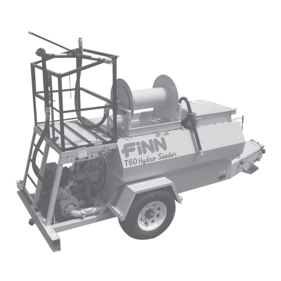
Summary of Contents for Finn HydroSeeder T60-II MD
- Page 1 Activate Activate Your Warranty Your Warranty By Registering By Registering TODAY!!! TODAY!!! 9281 LeSaint Drive • Fairfield, Ohio 45014 Phone (513) 874-2818 • Fax (513) 874-2914 Sales: 1-800-543-7166 T60-II HydroSeeder ® Parts and Operator’s Manual Model MD Serial No. LBT60-MO...
- Page 2 NOTES...
- Page 3 IF FINN CORPORATION DOES NOT HAVE YOUR COMPLETED REGISTRATION FORM ON FILE, YOUR WARRANTY CLAIM WILL BE DENIED. Once your FINN equipment has been registered, your FINN Limited Warranty will be activated per the warranty statement on the next page.
- Page 4 Follow the instruction sheet, on property damage sustained by a person claiming to be a third party how to use your Finn Oil Analysis Kit that comes with the Kit. Failure beneficiary of a surviving warranty under the law of any jurisdiction.
-
Page 5: Table Of Contents
Definition of Hydroseeding ........6 The FINN HydroSeeder® and How It Works ..... . . 6 Towing Vehicle . - Page 6 INDEX Pump Maintenance ........23–25 Factory Tolerances .
-
Page 7: Safety First
SAFETY FIRST With any piece of equipment, new or used, the most important part of its operation is SAFETY! FINN Corporation encourages you and your employees to familiarize yourselves with your new equipment and stresses safe operation. The first five pages of this manual are a summary of the main safety aspects associated with this unit. -
Page 8: Hydroseeder® Safety Summary Section
Practice all other usual and customary safe working precautions. Above all, remember that safety is up to you. The FINN HydroSeeder® is designed to mix and apply water, seed, fertilizer, agricultural lime, and hydraulic mulch to the prepared seedbed. The resultant slurry from mixing one or more of the above materials may react, causing harmful or deadly gasses within the tank. - Page 9 5. The driver of the carrying or towing vehicle is respon- 2. Never engage (turn on) sible for the safety of the operator(s) of the machine. clutch when both Make sure the driver is aware of and avoids all recirculation dis- possible hazards to the operator(s) of the machine, charge valves are closed.
- Page 10 Provide continuous ventilation or proper breath- 9. It is recommended that only authorized, genuine ing apparatus. FINN replacement parts be used on the machine. If tank must be entered, personnel entering the 10. Do not use either cold start fluid, if engine is tank must be tethered to a lifeline.
- Page 11 CURRENT SET OF SAFETY DECALS WA R NING B U R N H A Z A R D ! C ontents c ould be under pres s ure. DO NOT c ome in c ontac t with material. E ns ure material in line is not hot before loos ening c lamps or opening valves .
-
Page 12: Operation And Maintenance Section
® FOR FINN T60 SERIES II HYDROSEEDER This manual gives you step-by-step instructions for the operation and maintenance of the FINN T60 HydroSeeder®. For best results and to ensure longer life of the equipment, please follow the instructions carefully. For your safety, read the entire manual before operation of this unit. - Page 13 NOTICE Mounting the HydroSeeder® to the truck must allow for tire clearance and frame twist. Place hard wood spacers along the length of truck rails or use FINN Spring-Mounting Kit (part number 011562) or equivalent. 3. Place chains over the HydroSeeder® and around truck bed and secure with binders. Secure the HydroSeeder®...
-
Page 14: Attachments
ATTACHMENTS 1. Discharge Hoses: Discharge hoses are available in 50 ft (15.2 m) and 100 ft (30.5 m) lengths up to a total of 150 ft (45.7 m). Hose of a greater length may adversely affect the discharge distance and the discharge time of the HydroSeeder®. All connections are cam- lock, quick-operating fittings, including the connection to the end of the discharge piping. - Page 15 (see Figure 1, page 9): 1. Turn thumb nut clockwise until stem rises to maximum height. 2. Remove cap and fill cap with sodium- (water soluble) based grease (FINN part number 000698). Do not use lithium-based (chassis lube) grease. 3. Replace cap.
-
Page 16: Valve Operation
VALVE OPERATION A. THREE-VALVE OPERATION (BASE UNIT) The base HydroSeeder® is equipped with three independently operated ball valves to control slur- ry flow. See Figure 2 below. The first valve is the recirculation valve. An open recirculation valve allows flow back into the tank. The second valve is the pump discharge valve. An open pump dis- charge valve allows slurry to flow through the discharge hose. -
Page 17: Valve Operation (Platform/Boom Option)
B. VALVE OPERATION (PLATFORM/BOOM OPTION) The platform option is equipped with two independently operated ball valves to control slurry flow. See Figure 3 below. With the platform option, discharge of the slurry is accomplished two different ways; either through the discharge boom or through a discharge hose that is coupled to the end of the discharge boom. -
Page 18: Starting Procedure
The tables on page 13 show loading versus coverage rates for the FINN T60 II. Table A shows rates for one-step applications. The coverage area is determined by the fiber mulch capacity of the HydroSeeder®... - Page 19 TABLE A USING SEED, FERTILIZER, AND MULCH Unit Amount of Material in Tank in pounds (kilograms) Coverage Area Seed Fertilizer Mulch sq ft (sq. m) T60 II 46 (21) 53 (24) 200 (91) 5,790 (535) Table is based on 1,500 lb (680 kg) of mulch, 400 lb (181 kg) of fertilizer, and 345 lb (156 kg) of seed at 8 lb (3.6 kg) / 1,000-sq ft per acre.
-
Page 20: Tank Capacity Chart
TANK CAPACITY CHART 600 Gallons BOTTOM T-60 II Gallons in. (cm) From in. (cm) From (Liters) Bottom (2271) (20.3) 40.5 (102.9) (2082) 11.25 (28.6) 37.25 (94.6) (1893) 14.25 (36.2) 34.25 (87.0) (1703) 16.75 (42.5) 31.75 (80.6) (1514) 19.5 (49.5) (73.7) (1325) (55.9) 26.5... -
Page 21: Loading
LOADING WARNING Take care not to lose pens, lighters, etc. from shirt pockets, or drop pieces of paper or plas- tic bags into the tank, as these might plug the slurry system. Failure to comply could result in death or serious injury. Failure to comply could also result in product or property damage. 1. -
Page 22: Loading And Mixing Bfm, Fgm, Smm And Other Highly Viscous
NOTICE Hydraulic system will overheat if agitator shaft is jammed for extended period. This will damage hydraulic oil and system components. B. Fiber mulch – Empty the entire bag or cut open bag and drop in the sections of fiber. The amount of mulch to be used should be loaded by the time the water level is at 3/4 full. - Page 23 F. When discharge stream is clear, open recirculation valve and close discharge valve. After recirculation stream is clear, disengage (turn off) clutch. G. Replace coupler gasket in the remote valve coupler (or in boom on the platform option). 4. Continue filling tank with water. 5.
-
Page 24: Prior To Application
PRIOR TO APPLICATION 1. Operator should familiarize himself with the area to be seeded and develop a plan to ensure uniform application. PLATFORM OPTION 2. Develop a plan for communication between operator and driver of the carrying or towing vehicle to signal for start, stop, turn, etc. through the use of the signal horn. 3. -
Page 25: Application Of Slurry
APPLICATION OF SLURRY I. GENERAL APPLICATION TECHNIQUES DANGER Do not spray toward power lines, transformers or other high voltage conductors. Failure to comply will result in death or serious injury. CAUTION The driver of the carrying vehicle should remain alert for hazards to the operator, such as low power lines, hanging branches, etc. -
Page 26: Ii. Procedures When Using Hoses
II. PROCEDURES WHEN USING HOSES Always pump clear water through the hose before pumping mulch. If the inside hose liner is dry, it may dewater the mulch, causing hose to plug. A. DISCHARGE THROUGH HOSE OR HOSE REEL WITH REMOTE VALVE 1. -
Page 27: Reloading Procedure
RELOADING PROCEDURE 1. Start at step 2 in LOADING on page 15. 2. After last load of the day, refer to CLEANING AND MAINTENANCE. CLEANING AND MAINTENANCE AFTER FIRST 4 TO 8 HOURS OF OPERATION Torque wheel lugs. Torque again after 7 days (Trailer option only) to 75 lb-ft (102 N•m). DAILY 1. -
Page 28: Weekly Or Every 40 Hours Of Operation
WEEKLY OR EVERY 40 HOURS OF OPERATING TIME 1. Clean air cleaner following the instructions in the engine operator’s manual. 2. Lubricate all points on HydroSeeder® as outlined in DAILY in CLEANING AND MAINTE- NANCE on page 21. Additionally, lubricate the two grease fittings on clutch / pump. 3. -
Page 29: Hydraulic System
The hydraulic oil filter must be replaced on schedule with a 25 micron absolute filter – FINN part number 021618. The hydraulic system relief is factory-set at 2,250 psi (15,513 kPa). -
Page 30: Cleaning
C. CLEANING 1. To clean pump impeller (3), loosen the two Victaulic pipe clamps and remove suction pipe assembly. The eye of the pump impeller can then be seen through the pump suction cover (1) and is readily accessible for cleaning. 2. -
Page 31: Pump Assembly And Parts List
Drive Hub Locknut Suction Cover Bolt Clutch Retainer Suction Cover Washer 8 Retainer Bolt Radial Lip Seal 12LW Retainer Lockwasher Casing Bearing Electric Clutch Bearing Bolt Clutch Spacer Bearing Lockwasher Pump Frame Frame Bearing NOTE: See Parts Manual for FINN part numbers. -
Page 32: Troubleshooting Your Hydroseeder
TROUBLESHOOTING YOUR HYDROSEEDER® Because of the tremendous work load usually placed upon the HydroSeeder®, minor malfunctions will occur from time to time. If not remedied immediately, they could lead to poor performance and damage to the equipment. This section describes symptoms, possible causes, and the corrective actions to take. - Page 33 DANGER Severe injury can result from opening clamps when piping is hot. Before loosening any clamps, determine if the pipe is hot. If so, let it cool before attempting to perform repairs. Failure to comply will result in severe personal injury or death. B.
-
Page 34: Leaks
® TROUBLESHOOTING YOUR HYDROSEEDER Problem Probable Causes Suggested Solutions LEAKS: Tank Bearing Lack of lubrication – seal worn Replace seal and follow lube schedule. Bolts not tightened Tighten uniformly to 25 lb–ft (34 N•m). Pressure Pipe Clamps Rubber seal cracked, pinched, or Replace, always grease seal torn. -
Page 35: Valve
® TROUBLESHOOTING YOUR HYDROSEEDER Problem Probable Causes Suggested Solutions VALVE: Valve stuck Frozen Thaw out ice and lubricate; leave in discharge position during storage. Constant plugging during operation Foreign material in slurry Drain and clean out tank; check storage for foreign materials. Constant plugging during loading Loading HydroSeeder®... -
Page 36: Lubrication And Fluids Chart
Figure 7 – Lubrication and Adjustment Points... - Page 37 LUBRICATION AND FLUIDS CHART Ref. No. Location Lubricant Frequency Number Check Grease Level in Automatic Pressure Lubricator Daily Grease Agitator Shaft Bearings Daily Grease Discharge Swivel Daily Check Engine Oil Level Daily Change Engine Oil and Filter See Engine Manual Grease Pump Bearings Weekly Check Hydraulic Fluid Level...
- Page 38 NOTES...
-
Page 39: Parts Section
T60-II HydroSeeder ® Parts Manual Model MO WHEN ORDERING PARTS, BE SURE TO STATE SERIAL NUMBER OF MACHINE LBT60-MO... - Page 40 PLATFORM OPTION WHEN ORDERING PARTS, BE SURE TO STATE SERIAL NUMBER OF MACHINE LBT60-MO...
-
Page 41: Suction, Discharge, And Recirculation Piping
SUCTION, DISCHARGE, AND RECIRCULATION PIPING Ref. No. Part Number Description No. Required Base Platform Base Platform 080713 080713 Clump Assembly 002383 002383 Pressure Lubricator F60-0022-01 F60-0022-01 Clump Guard 080366 080366 Pipe Clamp 002439 002439 Clamp Gasket 1 per 1 per 002868 002868 90°... - Page 42 WHEN ORDERING PARTS, BE SURE TO STATE SERIAL NUMBER OF MACHINE LBT60-MO...
- Page 43 CLUTCH/PUMP ASSEMBLY Ref. No Part Number Description No. Required 080489 Pump Suction Cover 0X0720 Suction Cover Bolt 000Y07 Suction Cover Nut 080499 O-Ring 080488 Pump Impeller 080487 Pump Casing 080485 Mechanical Seal 0X0720 Suction Cover Bolt 000W07 Suction Cover Washer 080493 Radial Lip Seal 080498...
- Page 44 WHEN ORDERING PARTS, BE SURE TO STATE SERIAL NUMBER OF MACHINE LBT60-MO...
-
Page 45: Hydraulic System
HYDRAULIC SYSTEM Ref. No. Part Number Description No. Required 080806 Hydraulic Hose and Fittings Kit (Items 1- 16) 012044 Pressure Gauge 012087 MSAE - MJIC Adapter 023616 MNPT - MJIC Adapter 023911 FNPT - MSAE Adapter 055232 MSAE - MJIC Adapter 053019 MSAS - MJIC 45°... -
Page 46: Hydraulic Pump Drive Assembly
HYDRAULIC PUMP DRIVE ASSEMBLY Ref. No. Part Number Description No. Required 3/8 X 1 in. Lg. Bolt 080642 Hydraulic Pump F60-0016-03 Hydraulic Pump Mounting Plate 3/8 Hex Nut 080807 Coupling Half 5/8" Bore w/ Keyway 080809 Coupling Sleeve 080808 Coupling Half 1" Bore NOT SHOWN F60-0022-03 Hydraulic Pump Coupling Guard... -
Page 47: Hydraulic Agitator Drive Assembly
HYDRAULIC AGITATOR DRIVE ASSEMBLY Ref. No. Part Number Description No. Required 1/2 X 1-1/2 in. Lg. Bolt 080482 Hydraulic Motor F60-0016-01 Torque Arrestor Plate 1/2 Hex Nut 080523 Rigid Coupling Assembly 007420 Bearing and Seal Assembly (See page 40) 005081-02 Agitator Drive Stub Shaft NOT SHOWN F60-0022-02... - Page 48 NOTE: To tighten, turn nut, not bolt. Torque to 25 lb–ft (34 N m). 1-1/2" Agitator DO NOT OVER TORQUE! Shaft Through Back Side Outside Of Tank Wall Bearing Assy. #007420 (Includes Items 1–10) AGITATOR ASSEMBLY DRIVE WHEN ORDERING PARTS, BE SURE TO STATE SERIAL NUMBER OF MACHINE LBT60-MO...
-
Page 49: Agitator And Bearing Assembly
AGITATOR AND BEARING ASSEMBLY Ref. No. Part Number Description No. Required 007420 Bearing and Seal Assembly (Includes Items 1–10) 007417 Clamping Ring 1 per 007416 Agitator Rotary Gasket 1 per 006975 Agitator Bearing Gasket 1 per 007212-02 Flangette w/ Groove 1 per 003022 Bearing... -
Page 50: Discharge Boom
DISCHARGE BOOM OPTION Ref. No. Part Number Description No. Required 080736 Discharge Boom Assembly Consisting of: 080708 Boom Weldment 0X0624 3/8-16 UNC-2A x 1-1/2" Lg. Hex Hd Cap Screw 080559-01 Boom Handle 003299 Discharge Balance Torsion Spring 080560-02 Adjusting Collar Z0612SCP 3/8-16 x 3/4"... -
Page 51: Hatch Assembly
HATCH ASSEMBLY Ref. No. Part Number Description No. Required 080674 Hatch Lid 005565 Hatch Lid Lanyard 005433 Soft Latch 080675 Hatch Liner F60-0002-01 Hatch Shim 070627 Hatch Lid Hinge 002909 Handle 190044 Foam Gasket 12.5 (Ft) WHEN ORDERING PARTS, BE SURE TO STATE SERIAL NUMBER OF MACHINE LBT60-MO... - Page 52 WHEN ORDERING PARTS, BE SURE TO STATE SERIAL NUMBER OF MACHINE LBT60-MO...
-
Page 53: Common Loose Parts And Engine
COMMON LOOSE PARTS AND ENGINE Ref. No. Part Number Description No. Required F60-0005 Platform F75-0013 Right Support Angle F75-0012 Left Support Angle 080731 Fill Port Weldment 005280 Fill Port Plug 080378 Male Nyglass Coupler F60-0002 Tank Top 080589-02 Agitator Control Rod 022801 Clevis and Pin 080218... - Page 54 WHEN ORDERING PARTS, BE SURE TO STATE SERIAL NUMBER OF MACHINE LBT60-MO...
-
Page 55: Trailer Assembly Parts
TRAILER ASSEMBLY PARTS Ref. No. Part Number Description No. Required 085152 Rubber Stud Mount 005134 2-5/16" Ball Coupler OPTIONAL 005135 2-5/16" Ball 080043 2-1/2" Tow Ring 002909 Handle 080591-03 Safety Chain Rod Weldment 023915 Clevis Grab Hook - Self-Lock 190028 Safety Chain (3 ft) F60-0015 Fender... -
Page 56: Guard Rails
GUARD RAILS Ref. No. Part Number Description No. Required 080726 Right Guard Rail 080539-01 Gate 080521 Gate Spring Hinge 080537 Left Guard Rail 080536-18 Top Cross Rail 080536-13 Cross Rail F75-0008 Boom Support Plate NOT SHOWN F75-0014 Ladder WHEN ORDERING PARTS, BE SURE TO STATE SERIAL NUMBER OF MACHINE LBT60-MO... -
Page 57: Control Panel Wiring
(Black) CLUTCH BUTTON (White) IGNITION (Red) SWITCH CLUTCH SWITCH (Red) (White) (White) HOURMETER CLUTCH (White) HORN HORN BUTTON (Black) ENGINE PLUG CONTROL PANEL WIRING Ref. No. Part Number Description No. Required 007274 Hour Meter 080654 Ignition Switch 080654-K Ignition Key 020886 Horn Button 006499... -
Page 58: Trailer Wiring
LICENSE PLATE LIGHT BRAKE LH TAILLIGHT (Brown) (Brown) (Red) (Brown) TRAILER (Yellow) PLUG (Green) (Red) (White) BREAKAWAY SWITCH STARTER TAIL LIGHTS (Red) (Brown) NOT USED (Brown) RH TAILLIGHT BRAKE LEFT TURN RIGHT TURN (Yellow) (Green) GROUND ELECTRIC BRAKES (White) (Black) TRAILER PLUG CONNECTIONS TRAILER WIRING Ref. -
Page 59: Tool Kit / Seal Repair Kits
Narrow Fan Nozzle Assembly 006605 Narrow Fan Nozzle 080260 Male Adapter 160750 Reducer Bushing 006515 Coupler Gasket 012681A FINN Beige Aerosol Paint 080535 Remote Valve Assembly 012083 Full Port Ball Valve 080260 Male Adapter 080261 Female Coupler 160307 Close Nipple... - Page 60 NOTE: ITEM #4 (T60T DECAL KIT) INCLUDES ITEMS #5 – #35. Hydro Seeder Hydro Seeder WHEN ORDERING PARTS, BE SURE TO STATE SERIAL NUMBER OF MACHINE LBT60-MO...
-
Page 61: Decals
DECALS Ref. No. Part Number Description No. Required 023174 Decal "FINN" 012661-06 Decal "T60" 011595 Decal "Hydro Seeder" 080699 Decal Kit "T60" 031461 Decal "WARNING! Runaway Vehicle Hazard . . ." 012687 Decal "CAUTION! Hydraulic System Instructions . . ."... - Page 62 HOSE REEL WIRING MOTOR (Black) CIRCUIT BREAKER SOLENOID STARTER (Red) REEL (Blue) BUTTON WHEN ORDERING PARTS, BE SURE TO STATE SERIAL NUMBER OF MACHINE LBT60-MO...
-
Page 63: Hose Reel
HOSE REEL Ref. No. Part Number Description No. Required 080801 Hose Reel With 1/2 HP (12V) Motor 008188 Electric Motor 080801-01 Friction Brake Assembly 080801-02 90 Degree Inlet 080801-03 Bearing Housing Sub Assembly 080801-04 Spindle 1-1/2" Female Pipe - Ductile 080801-06 Gooseneck - 11"... - Page 64 NOTES...
Need help?
Do you have a question about the HydroSeeder T60-II MD and is the answer not in the manual?
Questions and answers