
Related Manuals for Henny Penny FSDE610


Summary of Contents for Henny Penny FSDE610
- Page 1 Installation Read the operating instructions prior to commissioning manual FlexFusion® ELECTRIC SPACE$AVER PLUS TEAM Model FSDE610 FM08-639-B en-US...
- Page 2 Henny Penny Corporation P.O.Box 60 Eaton,OH 45320 Phone +1 937 456-8400 Fax +1 937 456-8402 Toll free in USA Phone +1 937 417-8417 Fax +1 937 417-8434 www.hennypenny.com Installation instructions...
-
Page 3: Table Of Contents
Directory of contents 1 Introduction ................. 5 1.1 About this manual ................ 5 1.1.1 Explanation of signs .................. 6 1.2 Personnel qualifications .............. 7 1.3 Use of the unit ................... 7 1.4 Warranty .................... 7 2 Safety instructions ............. 8 3 Description of the unit ............. 10 3.1 Overview of the unit ............... 10 3.2 Unit and connection data ............... ... - Page 4 Directory of contents 7.3 Checking the inspection of the cooking chamber door ..... 36 7.4 Heating and rinsing the unit ............ 37 8 Putting the unit into service .......... 38 8.1 Nameplate .................. 38 8.2 Filling out the Start-up operation report ........ 38 Installation instructions...
-
Page 5: 1 Introduction
Introduction 1 Introduction 1.1 About this manual The installation instructions are part of the unit and contain information on safe installation of the unit. Observe the following notes and adhere to them: • Read the installation instructions completely prior to installation. •... -
Page 6: Explanation Of Signs
Introduction 1.1.1 Explanation of signs Imminent danger DANGER Failure to comply will lead to death or very severe injuries. Potential danger WARNING Failure to comply can lead to death or very severe injuries. Dangerous situation CAUTION Failure to comply can lead do slight to moderately severe injuries. Property damage NOTICE Failure to comply can cause property damage. -
Page 7: Personnel Qualifications
Introduction 1.2 Personnel qualifications Explanation of qualification Skilled personnel • A skilled person is someone who, on the basis of their technical training, knowledge and experience as well as familiarity with the applicable standards, can assess the assigned work and recognize pos- sible dangers. -
Page 8: 2 Safety Instructions
Safety instructions 2 Safety instructions The unit complies with applicable safety standards. Residual risks associated with operation or risks resulting from incorrect operation cannot be ruled out and are mentioned specifically in the safety instructions and warnings. The installation fitter must be familiar with regional regulations and observe them. - Page 9 Safety instructions Installation Risk of property damage and personal injury from improper installation • Ensure that the installation area has adequate load-bearing capacity. • Wear safety shoes and protective gloves. Electrical connection Risk of fire from improper connection • Observe applicable regional regulations of the electric supplier. •...
-
Page 10: 3 Description Of The Unit
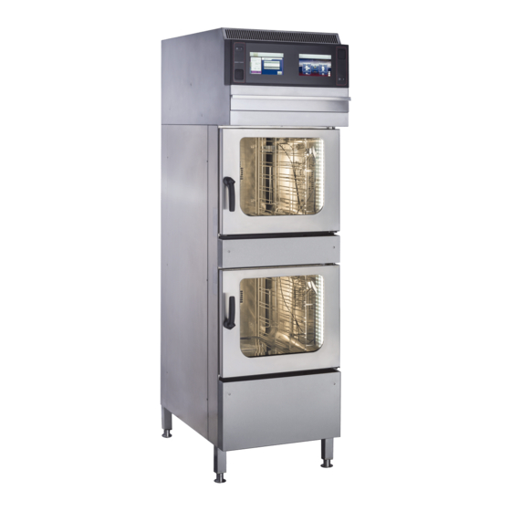
Description of the unit 3 Description of the unit 3.1 Overview of the unit Image: Floor-standing unit a Air outlet j Unit leg b Operating unit k Nameplate c Filter drawer l Discharge channel for bottom unit d Condensate baffle m Cooking chamber in bottom unit e Hang-in frame n Hand shower (optional) - Page 11 Description of the unit Size Emissions Heat dissipation at a connected load of 400 V Latent heat (W) 2808 Sensible heat dissipation (W) 1872 Noise level (db(A)) < 65 Operating environment Temperature (°C (°F)) 5 (41 ) — 40 (104 ) Relative air moisture (%) non-condensing Electrical connection...
- Page 12 Description of the unit Size Fuse (A) Voltage (V) Connected load (kW) 15.8 Fuse (A) Type of connection 2PE AC 50/60 Hz Voltage (V) Connected load (kW) 10.6 Fuse (A) Voltage (V) Connected load (kW) 13.8 Fuse (A) Type of connection 1NPE AC 50/60 Hz Voltage (V) Connected load (kW)
- Page 13 Description of the unit Size Softened drinking water (l/h 20 (5,28) (gal/h)) Water consumption for Combisteaming * Softened drinking water (l/h 4,4 (1,16) (gal/h)) Water consumption for WaveClean cleaning program * Softened drinking water (l (gal)) 2,5 l (0,66) Drinking water (l (gal)) 35 l (9,25) Waste water connection Waste water type...
- Page 14 Description of the unit Basic setting Parameter Standard Range of Explanation value adjustment Volume unit (ml) Milliliter (ml) (fl.oz.) Fluid ounce (fl.oz.) Imperial Imperial (fl.oz.) Imperial fluid ounces (fl.oz.) U.S. (fl.oz.) U.S. fluid ounces Water filter 0 — 99900 l Water quantity up to the maintenance maintenance (26393,66 gal)
- Page 15 Description of the unit Basic setting Parameter Standard Range of Explanation value adjustment Format for cooking 0 = hh:mm Display format for cooking program times program times 1 = mm:ss 2 = automatic Installation instructions...
-
Page 16: 4 Transporting The Unit
Transporting the unit 4 Transporting the unit Risk of property damage and personnel injury from tipping unit CAUTION • Stay clear of lifted unit. • Move lifted unit carefully. Risk of property damage from improper transport NOTICE • Transport the unit upright. •... - Page 17 Transporting the unit 1. Remove the packaging. 2. Pull the protective film off the unit. 3. Remove all packaging material from the cooking chamber. 4. Clean the unit (See Operating instructions). 5. Enter the information from the nameplate into the Start-up operation report.
-
Page 18: 5 Installing The Unit
Installing the unit 5 Installing the unit Risk of crushing from improper installation CAUTION • Protect the unit and work area during installation and alignment. Risk of fire from failure to observe applicable regional fire preven- CAUTION tion regulations • Observe applicable regional fire prevention regulations. Risk of property damage from overheating of the unit NOTICE •... -
Page 19: Lifting The Unit Off The Pallet
Installing the unit The following clearances from walls, ceilings or other equipment must be maintained when installing the unit: • Clearance to deep-fat fryers, at least one length of the hand shower at left and right. 5.2 Lifting the unit off the pallet Risk of property damage and personnel injury from tipping unit CAUTION •... -
Page 20: Inspecting The Recirculation Hood Filter
Installing the unit 5.5 Inspecting the recirculation hood filter Image: Recirculation hood filter a Condensation baffle e Vapor inlet b Filter drawer f Filter mat (yellow) c Air outlet g Air filter d Recirculation hood h Activated charcoal filter Prerequisite Unit dead Step ladder set up securely 1. - Page 21 Installing the unit • Follow the manufacturer's instructions for using the means of fastening. Depending on the size, it is essential that certain combisteamer types or combisteamers used in combination with a Stapelkit (stacking kit), a recirculation hood, an underframe or base cabinet be secured to prevent tipping.
- Page 22 Installing the unit Image: A: Position of floor plate; B: floor plate bolted to the floor a Cap nut d Floor plate b Holding plate e Lag bolt c Upright bolt f Unit leg Requirements The floor must support the weight of the unit The floor must be clean and suitable for the manner of fastening Unit set up and aligned in accordance with the planning drawing 1.
- Page 23 Installing the unit Image: A: Position of floor plate; B: floor plate glued to the floor a Cap nut d Floor plate b Holding plate e Unit leg c Upright bolt Requirements The floor must support the weight of the unit The floor must be clean and suitable for the manner of fastening Unit set up and aligned in accordance with the planning drawing 1.
-
Page 24: 6 Connecting The Unit
Connecting the unit 6 Connecting the unit Risk of personal injury and property damage from electric shock DANGER • Before working on the unit, ensure that the unit is dead. • Do not operate the unit with the housing open. Risk of injury from sharp edges CAUTION •... -
Page 25: Making The Electrical Connection
Connecting the unit 1. Carefully press in the rear panel. 2. Screw in the screws on the rear panel. The rear panel must be in contact with the unit on all sides. 6.2 Making the electrical connection Electrical installation work Electrical installation work on the electric system and the unit may only be performed by a specialist company, which is approved by the electric utility company in the particular region. - Page 26 Connecting the unit Install an all-pin separating device if the unit will be connected permanently to the electrical supply mains. Plug-in connection Risk of property damage and personal injury from improper instal- CAUTION lation • The plug-in connection must be readily accessible. If the unit is connected with a plug to the electrical supply mains, use plugs and sockets according to IEC60309.
-
Page 27: Connecting The Electrical Connection Line
Connecting the unit Potential equalization Image: Potential equalization symbol The unit can be included in a potential equalization system by means of appropriately sized wiring. 6.2.1 Connecting the electrical connection line Risk of personal injury and property damage from electric shock DANGER •... -
Page 28: Connecting The Power Optimization System
Connecting the unit 5. Close the housing (see "Opening and closing the housing"). 6. Fill out the start-up operation report. 6.2.2 Connecting the power optimization system Risk of personal injury and property damage from electric shock DANGER • Before working on the unit, ensure that the unit has been disconnected from the power supply. -
Page 29: Connecting The Potential Equalization
Connecting the unit 5. Register the power optimization system in the basic settings of the control (see "Making the basic settings of the control"). 6. Fill out the Start-up operation report. 6.2.3 Connecting the potential equalization Image: Connecting the potential equalization 1. - Page 30 Connecting the unit Image: Connecting the kitchen guiding system a RJ45 socket d Network cable b RJ45 connector e Ferrite ring c Threaded cable connection Prerequisite Unit dead Housing opened 1. Pull the network cable into the unit through the cable gland. 2.
-
Page 31: Performing The Basic Setting Of The Control
Connecting the unit 6.4 Performing the basic setting of the control Image: Main menu a Main menu d "Unit functions" button b FlexiHelp button e Back button c Language selection 6.4.1 Changing the basic setting of the control By entering the password "2100", the basic setting for the installation can be displayed and changed. -
Page 32: Making The Water Connection
Connecting the unit 6.5 Making the water connection Drinking water installation tasks Drinking water installation tasks on drinking water lines and the unit may only be performed by a specialist company, which is approved by the drinking water utility company in the particular region. The applicable regional regulations, standards and guidelines must be observed, as well as the connection conditions imposed by the drinking water utility company responsible. -
Page 33: Connecting The Drinking Water Connection Line
Connecting the unit 6.5.1 Connecting the drinking water connection line Image: Water connection a Softened drinking water d Drinking water connection b Connection line e Backflow preventer c Softened drinking water f Drinking water connection Prerequisite Water pressure complies with specifications (see "Unit and connection data") Backflow preventer installed Pressure-resistant connection lines suitable for tap water are... -
Page 34: Connecting Softened Drinking Water To Both Connections
Connecting the unit 6.5.2 Connecting softened drinking water to both connections Image: Connecting softened drinking water to both connections a Backflow preventer d T-piece b Connection line e Seal c Dirt filter f Softened drinking water If only softened drinking water is available at the installation site, use a T-piece to connect both water connections on the unit to each other. -
Page 35: Connecting The Waste Water Line To A Permanent Connection
Connecting the unit Technical qualifications for waste water installation tasks Waste water installation tasks on waste water lines and the unit may be carried out only by a waste water specialist provided by the specialist company contracted. 6.6.1 Connecting the waste water line to a permanent connection Image: Waste water line with vacuum breaker to a permanent connection a Waste water mains d Pipe clamp... -
Page 36: 7 Testing The Function
Testing the function 7 Testing the function Risk of personal injury and property damage from unsuccessful DANGER operational check • Do not put the unit into service. • Contact customer service. Prerequisite Electrical connection made Water connection made Waste water connection made Unit cleaned 7.1 Inspecting the recirculation hood Prerequisite Cooking chamber door closed... - Page 37 Testing the function 2. Open the cooking chamber door during operation. The unit shuts off the heating function. The fan comes to a stop. The monitoring of the cooking chamber door is functioning. 3. Close the cooking chamber door. 4. Switch off the unit. 5.
- Page 38 Putting the unit into service 8 Putting the unit into service If the unit is not put into service immediately after being connected and the INFORMATION function check, all inspections must be repeated. Prerequisite Electrical connection made Water connection made Waste water connection made Function successfully tested Housing closed...
- Page 39 Putting the unit into service General information Obvious damage to the unit? What and where?: Unit levelled? General information Unit fastened to floor? secured against tipping secured against shifting Screwed to floor Screwed to floor Glued to floor Glued to floor Electrical connection Electrical connection made properly? Potential equalization...
- Page 40 Putting the unit into service Basic setting of the control Volume unit set? fl.oz. (Imperial) fl.oz. (U.S.) Power optimization system set? Water filter maintenance set? No maintenance message Maintenance message at: l (gal) Network configuration set? DHCP IP address: Subnet mask: Gateway: Kitchen guiding system set? Active...
- Page 41 Putting the unit into service Final notes Was the unit put into service? Comments: Operator trained? Electrical installation was made by: Signature Company Installation fitter Place, date The connection to a kitchen guiding system was made by: Signature Company Installation fitter Place, date Water installation was made by: Signature...
- Page 42 Putting the unit into service Installation instructions...
- Page 44 Henny Penny Corporation P.O.Box 60 Eaton,OH 45320 Phone +1 937 456-8400 Fax +1 937 456-8402 Toll free in USA Phone +1 937 417-8417 *FM08-639-B* Fax +1 937 417-8434 www.hennypenny.com Henny Penny Corp., Eaton, Ohio 45320, Revised 12/13/2018...
Need help?
Do you have a question about the FSDE610 and is the answer not in the manual?
Questions and answers