Advertisement
Quick Links
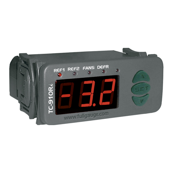
1. DESCRIPTION
TC-910Ri
The
is a temperature controller for freezing goods with two stages for freezing. It also
commands the evaporator fans and manages the defrosting cycles.
It includes two independent hourmeters for counting the refrigeration output operation time. When the
programmed amount of hours before maintenance is reached (ex: compressors) a display indication is
given.
In order to increase the system efficiency, the
time, which enables the collection of remaining gas before starting the defrosting cycle.
Product complies with CE (European Union) and UL Inc. (United States and Canada).
2. APPLICATION
• Counters
• Refrigerating balconies
3. TECHNICAL SPECIFICATIONS
- Power supply:
TC910Ri - 115 or 230Vac ±10%(50/60Hz)
TC910RiL - 12 or 24Vac/dc
- Control temperature:
-50 to 75° C / -58 to 167°F
- Operating temperature:
0 to 50°C / 32 to 122°F
- Operating humidity:
10 to 90% RH (without condensation)
- Resolution:
0.1°C from -10 to 75°C and 1°C outside this range
1°F in all range
- Load current (outputs):
REF1: 5(3)A/ 250Vac 1/8HP (compressor, solenoid valve or contactor)
REF2: 5(3)A/ 250Vac 1/8HP (compressor, solenoid valve or contactor)
FANS: 5(3)A/ 250Vac 1/8HP (evaporator fans)
DEFR: 5(3)A/ 250Vac (defrost - resistance or hot gas)
- Dimensions:
71 x 28 x 71mm
- Sensors:
S1: Room sensor - Black cable
S2: evaporator sensor - Gray cable
CLASSIFICATION ACCORDING TO IEC60730-2-9 STANDARD:
- Temperature limit of the installation surface:
- Type of construction:
Built-in electronic controller
- Automatic action:
Type 1
- Control of pollution:
Level 2
- Impulse voltage:
1,5kV
- Temperature for the test of sphere pressure:
- Insulation:
Class II
4.
CONFIGURATIONS
4.1 -
Control temperatures adjust (SETPOINTS):
SET
- Press
for 2 seconds until appears
working temperature adjusted
.
Use
and
record it.
Soon after
it
(economic setpoint ) will appear, repeats the procedure above modify the
value and leav the function.
e
Fun
Description
Access code:123 (one hundred and twenty-three)
Control differential for the 1st stage (hysteresis 1)
Control differential for the 2nd stage (hysteresis 2)
Minimum setpoint allowed to the end user
Maximum setpoint allowed to the end user
Delay when the instrument is powered on
Act point of high room temperature alert (S1)
Refrigeration time (interval between defrosts)
Compressor delay after on (on - off)
Compressor delay after off (off - on)
Compressor status with detached ambient sensor (S1)
Defrost when the instrument is powered on
Evaporator temperature (S2) for end defrost
Maximum duration of defrost (for security)
Fan turned on during defrost
Defrost type
Locked temperature indication (S1) during defrost
Draining time (dripping of defrost water)
Evaporator temperature (S2) for fan return after draining
Maximum time of fan return after draining (fan-delay)
Fan on with compressor off (refrigeration)
Fan stopped for high temperature in the evaporator
Offset indication for ambient sensor (Offset S1)
Offset indication for evaporator sensor (Offset S2)
Pre-defrosting time
Max. operation time for output REF1 before maintenance.
Max. operation time for output REF2 before maintenance
TC-910Ri
TWO STAGE CONTROLLER
FOR REFRIGERATION
Ver.01
TC-910Ri
allows the adjustment of a pre-defrosting
50°C
75°C and 125°C
, and release it after that
. It w
ill appear
keys to change the value and then press
4.3 - Parameters description
F01 - Access code (123)
To change the parameters it is necessary to use the access code.It is not necessary to use the access
code to visualize the adjusted parameters.
F02 -
Control differential for the 1st stage (hysteresis 1)
It is the difference of temperature (hysteresis) between to turn OFF and turn ON the 1st stage (REF1).
Example: To control the temperature in 4.0°C with differential of 1.0°C. Soon, the refrigeration will be
turned off in 4.0°C and turned on again in 5.0°C (4.0 + 1.0)
F03 -
Control differential for the 2nd stage (hysteresis 2)
It is the difference of temperature (hysteresis) between to turn OFF and turn ON the 2nd stage (REF2).
F04 - Minimum setpoint allowed to the end user
F05 - Maximum setpoint allowed to the end user
Electronic limits whose purpose is prevent that too high or too low setpoint temperatures are regulated.
F06 - Delay when the instrument is powered on
When the instrument is powered on, its control is kept disabled during a time, delaying the start of
process. During this time, it works only as temperature indicator. It serves to prevent demand of electric
energy peaks, in case of lack or return of the same and when exists a lot of equipment connected on the
same net. For this, just adjust different times for each equipment. This delay may be of compressor or
defrost (when exist defrost on turn on).
F07 - Act point of high room temperature alert
If the room temperature (sensor S1) reaches this point during refrigeration, this will be signaled visually
through the indication blinking on display.
08 - Refrigeration time (interval between defrosts)
It is the time which compressor will turn on and turn off only for room temperature and starts to be
counted when the fan is turned on , after fan-delay stage (fan return after draining).
Attention, the defrost will only initiate if the temperature in S2 (sensor of the evaporator) will be lesser of
what the indicated one in F13.
F09 - Compressor delay after on (on-off)
It is the minimum time that compressor will keep on, it means, space of time between the last drive and
the next stop. It serves to prevent high voltage events in the electric network.
F10 - Compressor delay after off (off-on)
It is the minimum time that compressor will keep off, it means, space of time between the last stop and
the next drive. It serves to alliviate the discharge pressure and to increase the time of useful life of the
compressor.
F11 - Compressor status with detached ambient sensor (S1)
If the room sensor (S1) will be danified or outside the specified range, the compressor assumes the
configured status in this function.
Example: For counters of fruits, it is better to keep the compressor off. In counters of meat it is better to
keep the compressor on.
and the
SET
to
F12 - Defrost when the instrument is powered on
to
It makes possible the accomplishment of a defrost at the moment that controller is energized, for
example, in the return of electrical energy (in case of energy lack)
CELSIUS
Min
Max
Unit
-
-
-
1
20.0
º C
1
20.0
º C
-50.0
75.0
º C
-50.0
75.0
º C
0
30
min.
-50.0
75.0
º C
1
999
min.
0
999
sec.
0
999
sec.
0 - off
1 - on
-
0 - no
1 - yes
-
-50.0
75.0
º C
0 - disable
90
min.
0 - no
1 - yes
-
0 - electric
1 - hot gas
-
0 - no
1 - yes
-
0
30
min.
-50.0
75.0
º C
0
30
min.
0 - no
1 - yes
-
-50.0
75.0
º C
-20.0
20.0
º C
-20.0
20.0
º C
0
120
seg.
0 - disable
999
x10h
0 - disable
999
x10h
FAHRENHEIT
Default
Min
Max
Unit
Default
-
-
-
-
1.5
1
36
º F
1.5
1
36
º F
-50
-58
167
º F
75
-58
167
º F
0
0
30
min.
75
-58
167
º F
240
1
999
min.
0
0
999
sec.
0
0
999
sec.
1 - on
0 - off
1 - on
-
0 - no
0 - no
1 - yes
-
40
-58
167
º F
45
0 - disable
90
min.
0 - no
0 - no
1 - yes
-
0 - electric
0 - electric
1 - hot gas
-
0
- electric
0 - no
0 - no
1 - yes
-
10
0
30
min.
0
-58
167
º F
1
0
30
min.
1 - yes
0 - no
1 - yes
-
1 - yes
75
-58
167
º F
0
-36
36
º F
0
-36
36
º F
0
0
120
seg.
500
0 - disable
999
x10h
500
0 - disable
999
x10h
UL-Underwriters Laboratories
-
3
3
-58
167
0
167
240
0
0
1 - on
0 - no
104
45
0 - no
0 - no
10
32
1
167
0
0
0
500
500
Advertisement

Related Manuals for Full Gauge Controls TC-910R


Summary of Contents for Full Gauge Controls TC-910R
- Page 1 TC-910Ri TWO STAGE CONTROLLER FOR REFRIGERATION Ver.01 UL-Underwriters Laboratories 1. DESCRIPTION 4.3 - Parameters description TC-910Ri is a temperature controller for freezing goods with two stages for freezing. It also commands the evaporator fans and manages the defrosting cycles. F01 - Access code (123) It includes two independent hourmeters for counting the refrigeration output operation time.
- Page 2 F13 - Evaporator temperature (S2) for end defrost 5.3 - Process stage, elapsed time, sensors S2 temperature If the temperature in the evaporator (sensor S2) reaches the adjusted value, the end of defrost will be for hourmeter time. temperature. With this, the defrost process is optimized. Press .
- Page 3 8. WIRING DIAGRAM PROTECTIVE VINYL: This adhesive vinyl (included inside the packing) protects the instruments against water drippings, as in commercial refrigerators, for example. Do the application after finishing the electrical connections. 115V 230V Remove the protective paper (12V ) (24V ) and apply the vinyl on the entire Power...
Need help?
Do you have a question about the TC-910R and is the answer not in the manual?
Questions and answers