Advertisement
Quick Links
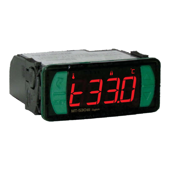
1. DESCRIPTION
e
MT-530
%uper
The
has three outputs: one for temperature control, one for humidity control and a
third auxiliary output that acts as a second stage temperature control, humidity control, alarm or timer
cyclical.
This controller is indicated for low and medium relative humidity (10-85% non-condensing). Its
temperature sensors and humidity are united in a single bulb, reducing installation space and wiring. It
also includes an audible alarm (buzzer) and an intelligent system locking functions, preventing
unauthorized people from changing the control parameters.
The instrument features a serial communication for connection to Sitrad .
Product complies with UL Inc. (United States and Canada).
2. APPLICATION
• Humidifiers / dehumidifiers
• Grains drying
• Laboratories
• Surgical rooms
• Climatized cellars
• Information technology centers
*For high percentage of humidity in the presence of water condensation, use the model AHC-80 Ri
plus.
3. TECHNICAL SPECIFICATIONS
MT-530E Super: 115 or 230 Vac ±10%(50/60 Hz)
Power Supply
MT-530EL Super:
-10 to 70.0 ºC
Control Temperature
14 to 158 ºF ±3°F (with resolution of 0.1°F)
Operation temperature
0 to 50°C / 32 to 122°F
Control humidity
10 to 85% RH
Operation humidity
10 to 85% RH (without condensation)
Therm :16(8)A/250Vac 1HP
Load current
Humid
Aux : 5(3)A/250Vac 1/8HP
76 x 34 x 77 mm / 2,9 x 1,33" x 3,03"
Dimensions (mm)
W H D
71 ± 0,5 x 29 ± 0,5 mm (see item 5)
Dimensions of the clipping for fixing
2,79" ± 0,02" x 1,14" ± 0,02"
of the instrument
4. INDICATIONS AND KEYS
Aux output led indicator
Humidity output led indicator
Therm output led indicator
Menu key facility
Key Set
%uper
MT-530
5. INSTALLATION - ELECTRICAL CONNECTIONS AND PANEL
Panel
(Side View)
IMPORTANT
THE USE OF APPROPRIATE TOOLS IS ESSENTIAL TO AVOID DAMAGE IN THE
CONNECTIONAT INSTRUMENT TERMINALS:
SCREWDRIVER SLOT 3/32''(2.4mm) FOR ADJUSTMENTS IN THE SIGNAL TERMINALS;
SCREWDRIVER PHILLIPS #1 FOR ADJUSTMENTS IN THE POWER TERMINALS.
ATTENTION
FOR INSTALLATIONS WHERE A SEALING IS REQUIRED TO AVOID LIQUID CONTACT, THE
CUT FOR THE CONTROLLER MUST BE OF 70,5X29mm MAXIMUM. THE SIDE LOCKS
MUST BE FIXED SO IT PRESSES THE RUBBER SEALING AVOIDING INFILTRATION
BETWEEN THE CUTAND THE CONTROLLER.
LEGEND
1
Yellow
2
Brown
3
Green
e
MT-530
%uper
DIGITAL CONTROLLER AND INDICATOR
OF TEMPERATURE AND HUMIDITY
WITH SERIAL COMMUNICATION TO SITRAD
Functions
Buzzer
System
Serial
lockdown
supervisor
programming
®
12 or 24 Vac/dc +10%
±1.5°C
(with resolution of 0.1°C)
± 5%R
H (with resolution of 0.1%RH)
: 5(3)A/250Vac 1/8HP
9"
x x
Buzzer output led indicator
Lock functions led indicator
Temperature unit led indicator
Con
71
± 0,5
mm
Dimension of the clipping
for setting of the
instrument in panel
Panel
(Front View)
Conne
5 6 7 8
1
4
Red
IP 65
FRONT
Protection
Modbus
level
Protocol
6. OPERATIONS
6.1 Facilitated menu map
By pressing the button
below:
FUNCTION SELECTION
;
MT-530
MANUAL
DEFROST*
;
MT-530
THERM OUTPUT SETPOINT
;
MT-530
HUMID OUTPUT SETPOINT
;
MT-530
AUX OUTPUT SETPOINT*
;
MT-530
INHIBITOR BUZZER*
;
MT-530
Upper key
LOCK FUNCTION
;
Lower key
MT-530
* These parameters are displayed when necessary.
nection
115 Vac
RS - 485
-
+
A B
POWER
5 6 7 8
SUPPLY
9
10 11 12 13 14 15 16 17
1
2 3 4
ction
24 Vac/dc
RS - 485
-
+
A B
POWER
SUPPLY
9
10 11 12 13 14 15 16 17
2 3 4
24 Vac/dc
e
e
%u per
%u per
%u per
e
M T- 53 0
M T- 53 0
M T- 53 0
;
, it is possible to navigate through the function menus. See the map functions
%uper
%uper
%uper
%uper
%uper
%uper
%uper
Conne
ction
230 Vac
RS - 485
-
+
A B
5 6 7 8
9
1
2 3 4
Conne
ction
12 Vac/dc
RS - 485
-
+
A B
5 6 7 8
SUPPLY
9
1
2 3 4
12 Vac/dc
Power
Loads
evolution
E251415
EXIT THE MENU
;
MT-530
%uper
PROCESS VIEWER
;
MT-530
%uper
TOGGLE MEASUREMENT
DISPLAY
;
MT-530
%uper
CLEAR VALUES
MAX. AND MIN.
;
MT-530
%uper
TEMPERATURE RECORD
M N.
I
AND
M X.
A
;
MT-530
%uper
CONTROL FUNCTIONS
SHUTDOWN
;
MT-530
%uper
POWER
SUPPLY
10 11 12 13 14 15 16 17
POWER
10 11 12 13 14 15 16 17
Power
Loads
Advertisement

Related Manuals for Full Gauge Controls Evolution MT-530E Super


Summary of Contents for Full Gauge Controls Evolution MT-530E Super
- Page 1 evolution MT-530 %uper DIGITAL CONTROLLER AND INDICATOR OF TEMPERATURE AND HUMIDITY WITH SERIAL COMMUNICATION TO SITRAD IP 65 FRONT %u per %u per %u per M T- 53 0 M T- 53 0 M T- 53 0 Functions Buzzer System Serial Protection Modbus...
-
Page 2: Advanced Operations
6.3.4 Registers of minimum and maximum measures 6.2 Facilitated key map < When the controller is on display temperature, the following shortcut keys are used for the following [rEg,] Pressing key or also through the quick access menu (see chapter 6), the message will functions: appear, followed by the minimum and maximum recorded temperatures.To turn the current minimum... - Page 3 CELSIUS FAHRENHEIT Description M n i Standard M x a Unit M n i M x a Unit Standard [,F24] -10.0 High ambient temperature alarm 70.0 158.0 °F 158.0 70.0 °C 14.0 [,F25] Low ambient humidity alarm [,f26] High ambient humidity alarm 100.0 100.0 [,F27]...
-
Page 4: Optional Items
Allows configuring the maximum time the output HUMID can stay activated without reaching the [eCal] Please contact Full Gauge Controls. setpoint before activating the audible alarm (BUZZER). To deactivate this function, just decrement the [no,,] value until the message is displayed. -
Page 5: Environmental Information
In case of any doubts, contact Full Gauge controls for assistance. Products manufactured by Full Gauge Controls, as of May 2005, have a two (02) year warranty, as of the date of the consigned sale, as stated on the invoice. They are guaranteed against manufacturing defects that make them unsuitable or inadequate for their intended use.
Need help?
Do you have a question about the Evolution MT-530E Super and is the answer not in the manual?
Questions and answers