Advertisement
Have this manual in the palm of
your hand by FG Finder application.
Manual
defrost
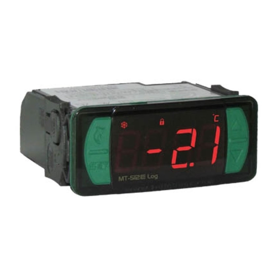
1. DESCRIPTION
Designed for cooling or heating application. MT-512
temperature sensor, 1 digital input, data logger, cyclic time for natural defrost, IP65 frontal, min-max
temperature record, sensor response time control, fast freezing mode, tamper-proof function, control
functions shutdown and RS485 serial communication port for Sitrad real-time monitoring and
e
management. The MT-512
Log allows you to configure the RS-485 communication port for the
MODBUS-RTU protocol. For more information about the implemented commands and the registration
table, contact Full Gauge Controls.
Product conforming to UL Inc. (United States and Canada) and NSF (United States).
2. SAFETY RECOMMENDATIONS
- Check the controller for correct assembling;
- Make sure that the power supply is off and that it is not turned on during the controller installation;
- Read the present manual before installing and using the controller;
- Use adequate Personal Protective Equipment (PPE);
- For application at sites subject to water spills, such as refrigerated cabinets, install the protecting vinyl
supplied with the controller;
- For protection under more critical conditions, we recommend the Ecase cover, which we make
available as an optional item (sold separately);
- The installation procedures should be performed by a qualified technician.
3. APPLICATIONS
• Refrigerated displays
• Walk-in coolers
• Hot cabinets
• Greenhouses
4. TECHNICAL SPECIFICATIONS
MT-512E Log 115 or 230 Vac ±10%(*) (50/60 Hz)
Power supply
MT-512EL Log
Control temperature
-50 to 105ºC (-58 to 221°F)(**)
Operating temperature
0 to 50 ºC / 32 to 122°F
NO -16A / 2HP
Maximum output current
NC - 500W / 1/10HP
Maximum consumption of device
1.5 VA
0,1°C / 0,1°F
Temperature resolution
Digital input
Configurable dry contact type
Operating humidity
10 to 90% RH (without condensation)
Dimensions (mm)
76 x 34 x 77 mm / 2,99" x 1,33" x 3,82 (WxHxD)
Cutout dimensions (mm)
71 ± 0,5 (2,79" ± 0,02") x 29 ± 0,5 mm (1,14 ± 0,02")
(*)
Admissible variation in relation to the voltage rating.
(**)
This device can measure and control temperatures of up to 200° C when used in conjunction with a model SB59 silicon
sensor cable (sold separately).
Note: Sensor cable length can be increased to up to 200 meters by the user by using a PP 2 x 24 AWG cable.
5. INDICATIONS AND KEYS
Defrost indication LED
Heating indication LED
Cooling indication LED
User-friendly
Menu Key (Flatec)
Set Key
e
MT-512
Log
6. WIRING DIAGRAM
6.1. Identifications (see Images I to IV)
- Image I: MT-512E Log, supplied at 115 Vac.
- Image II: MT-512E Log, supplied at 230 Vac.
- Image III: MT-512EL Log, supplied at 12 Vac/dc.
- Image IV: MT-512EL Log, supplied at 24Vac/dc.
IMPORTANT
THE USE OF APPROPRIATE TOOLS IS ESSENTIAL TO AVOID DAMAGE IN THE CONNECTION AT INSTRUMENT
TERMINALS:
SCREWDRIVER SLOT 3/32''(2.4mm) FOR ADJUSTMENTS IN THE SIGNAL TERMINALS;
SCREWDRIVER PHILLIPS #1 FOR ADJUSTMENTS IN THE POWER TERMINALS;
e
MT-512
DIGITAL INDICATOR AND CONTROLLER FOR
HEATING OR REFRIGERATION WITH NATURAL DEFROST
THROUGH COMPRESSOR SHUTDOWN AND
INTERNAL DATALOGGER
LOG
Datalogger
Function
Control
Serial
lock
functions
programming
shutdown
e
Log is equipped with 1 powerful 2HP relay, 1
12 or 24 Vac/dc +10%(*)
Functions lockdown indication LED
Control functions OFF indication LED
Temperature unit indication LED
Upper Key
Lower Key
Log
IP 65
FRONT
Supervisory
Degrees
Modbus
system
of protection
Protocol
Image I: MT-512E Log - 115Vac
A
B
D1
WIRING
TERMINALS
TEMPERATURE
SENSOR
Image II: MT-512E Log - 230 Vac
A
B
D1
WIRING
TERMINALS
TEMPERATURE
SENSOR
Image III: MT-512EL Log - 12Vac/dc
A
B
D1
WIRING
TERMINALS
POWER
12Vac/dc
TEMPERATURE
SENSOR
Image IV: MT-512EL Log - 24Vac/dc
A
B
D1
WIRING
TERMINALS
POWER
24Vac/dc
TEMPERATURE
SENSOR
6.2. Temperature sensor connection
- Connect the sensor wires to terminals '1 and 2': the polarity is not relevant.
- Length of the sensor cables can be increased by user himself to up to 200 meters, using a PP 2x24
AWG cable.
- For immersion in water, use a thermowell (Image VI - item 13), available in the Full Gauge Controls
product line (sold separately).
e
e
Lo g
Lo g
MT -51 2
MT -51 2
CONTROLLER
WIRING
TERMINALS
115 Vac
NC
NO
COMMON
LOAD
}
POWER
GRID
CONTROLLER
WIRING
TERMINALS
NC
NO
COMMON
230 Vac
LOAD
}
POWER
GRID
CONTROLLER
WIRING
TERMINALS
S u r g e P r o t e c t i v e
Device (SPD)
NC
NO
COMMON
(sold separately)
W i r i n g d i a g r a m f o r
i n s t a l a t i o n o f S P D i n
LOAD
magnectic contactor
A1 and A2 are the terminals of
the contactor coil.
}
POWER
GRID
CONTROLLER
W i r i n g d i a g r a m f o r
WIRING
instalation of SPD in line
TERMINALS
with loads
For direct drive take in to
consideration the specified
maximum current.
NC
NO
COMMON
LOAD
}
POWER
GRID
evolution
COMPONENT
E251415
A1
A2
LOAD
Advertisement
Table of Contents

Subscribe to Our Youtube Channel
Related Manuals for Full Gauge Controls MT-512e Log


Summary of Contents for Full Gauge Controls MT-512e Log
- Page 1 AWG cable. SCREWDRIVER SLOT 3/32''(2.4mm) FOR ADJUSTMENTS IN THE SIGNAL TERMINALS; - For immersion in water, use a thermowell (Image VI - item 13), available in the Full Gauge Controls SCREWDRIVER PHILLIPS #1 FOR ADJUSTMENTS IN THE POWER TERMINALS; product line (sold separately).
-
Page 2: Assembling Procedure
Use the pins according to table below, considering the set version: Hold the key down for 2 seconds until the message[SET,]. is displayed. The adjusted control temperature will be displayed when the key is released. Pins MT-512E Log MT-512EL Log < > Use the keys to change the value and then press to save. -
Page 3: Date And Time Adjustment
< > 8.3.8. Manual datalogger activation to change the value and press when ready to save the configured value and return to the function menu. To leave the menu and return to the normal operating mode (temperature indication), The manual activation requires function [,F23] to be configured with the value 2. By holding down the <... -
Page 4: Glossary Of Acronyms
B and , being the cable screen. [,,,2]- Manual operation The MT-512e Log allows you to configure the RS-485 communication port for the MODBUS-RTU protocol. For more information about the implemented commands and the registration table, contact Full Gauge Controls. - Page 5 If in doubt, please contact Full Gauge Controls. EXTENDED FRAME Products manufactured by Full Gauge Controls, as of May 2005, have a two (02) year SWITCHES warranty, as of the date of the consigned sale, as stated on the invoice. They are guaranteed...
Need help?
Do you have a question about the MT-512e Log and is the answer not in the manual?
Questions and answers