
Related Manuals for Allen-Bradley 1734


Summary of Contents for Allen-Bradley 1734
- Page 1 User Manual 1734 POINT I/O EtherNet/IP Adapters Catalog Number 1734-AENT, Series B...
- Page 2 Identifies information that is critical for successful application and understanding of the product. IMPORTANT Allen-Bradley, Rockwell Automation, ArmorPOINT, ControlLogix, Logix5000, POINT I/O, RSLinx, RSLogix 5000, Studio 5000, Studio 5000 Automation Engineering & Design Environment, Studio 5000 Logix Designer, and TechConnect are trademarks of Rockwell Automation, Inc.
-
Page 3: New And Updated Information
Added Set the Chassis Size by Using the Thumbwheels section. Updated Set the Network Address section with information about how to use a pen tip to set the thumbwheels. Rockwell Automation Publication 1734-UM018D-EN-E - September 2017... - Page 4 Summary of Changes Notes: Rockwell Automation Publication 1734-UM018D-EN-E - September 2017...
-
Page 5: Table Of Contents
Wire a POINT I/O Adapter ........17 Rockwell Automation Publication 1734-UM018D-EN-E - September 2017... - Page 6 Connection ..........65 Rockwell Automation Publication 1734-UM018D-EN-E - September 2017...
- Page 7 Configure the AB_ETHIP Driver ....... . 110 Rockwell Automation Publication 1734-UM018D-EN-E - September 2017...
- Page 8 Table of Contents Index viii Rockwell Automation Publication 1734-UM018D-EN-E - September 2017...
-
Page 9: Who Should Use This Manual
EtherNet/IP Adapter modules. Purpose of this Manual This manual is a reference guide for the 1734-AENT/B POINT I/O EtherNet/IP Adapter, a communications adapter for POINT I/O modules. It describes the procedures you use to install, wire, configure, troubleshoot, and use your adapter module. -
Page 10: System Components
4.0, Service Pack 6A or higher Ethernet switch Refer to manufacturer’s specifications 24V DC power supply 1734-EP24DC Associated media and connectors as needed Software RSLinx communications software, 9355-WAB, 9355-WABOEM, 9355-WABC version 2.31.00 or later Rockwell Automation Publication 1734-UM018D-EN-E - September 2017... -
Page 11: Related Documentation
Resource Description ® 1734 POINT I/O Selection Guide, publication 1734-SG001 A description and overview of the 1734 series I/O modules and compatible control platforms. EtherNet/IP Design Considerations Reference Manual, publication Using EtherNet/IP for Industrial Control. ENET-RM002. EtherNet/IP Modules in Logix5000 ™... -
Page 12: Common Techniques Used In This Manual
The Studio 5000® environment is the foundation for the future of Rockwell Automation® engineering design tools and capabilities. The Studio 5000 environment is the one place for design engineers to develop all elements of their control system. Rockwell Automation Publication 1734-UM018D-EN-E - September 2017... -
Page 13: Overview
Chapter Overview of the 1734 POINT I/O EtherNet/IP Adapter Overview This chapter provides an overview of the POINT I/O Series B EtherNet/IP adapter, its primary features, and how to use it. You need to understand the concepts discussed in this chapter to configure your adapter and use it in an EtherNet/IP control system. -
Page 14: What The Adapter Does
Chapter 1 Overview of the 1734 POINT I/O EtherNet/IP Adapter Some of the module’s features are as follows: • EtherNet/IP messages encapsulated within standard TCP/UDP/IP protocol • Common application layer with ControlNet and DeviceNet networks • Interfacing via Category 5 rated twisted pair cable •... -
Page 15: Physical Features Of Your Adapter
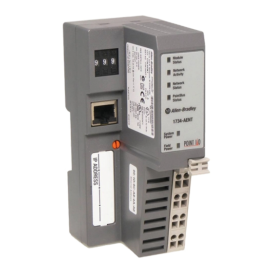
Overview of the 1734 POINT I/O EtherNet/IP Adapter Chapter 1 Physical Features of Your The 1734 Adapters have the following components: • Removable Terminal Block (RTB); Adapter • Network address Thumbwheel • Connector (one RJ45 EtherNet/IP connector) • Status indicators (Module Status; Network Status; POINTBus Status;... -
Page 16: Important Adapter Considerations
Considerations ATTENTION: You must only use Series C and above POINT I/O modules with 1734-AENT EtherNet/IP Adapters. Series A or Series B POINT I/O modules do not work with 1734-AENT EtherNet/IP Adapters (does not apply to POINTGuard modules). Thumbwheel Settings You can set the thumbwheels on the adapter to perform different functions. - Page 17 Overview of the 1734 POINT I/O EtherNet/IP Adapter Chapter 1 For example, if your system consists of one adapter and four I/O modules, set the chassis size to 5. One adapter Four I/O modules Chassis size = 5 1734-AENT Series B...
- Page 18 Chapter 1 Overview of the 1734 POINT I/O EtherNet/IP Adapter For example, set the thumbwheels to 802 to set the chassis size to 2, 803 to set the chassis size to 3, and so on up to 864 to set the chassis size to 64.
-
Page 19: Adapter Replacement
Overview of the 1734 POINT I/O EtherNet/IP Adapter Chapter 1 For more information, see Set the Network Address for POINT I/O Adapters on page Adapter Replacement Note that during a connection request from the controller, the chassis size setting is not communicated to the adapter. You must always set this chassis size using a separate operation. -
Page 20: Power Up A System For The First Time
Chapter 1 Overview of the 1734 POINT I/O EtherNet/IP Adapter • If a module separating two sets of contiguous missing modules is removed, the two sets merge into a single set. All the modules must be replaced before connections are permitted to any module in the set. -
Page 21: Understand The Producer/Consumer Model
Overview of the 1734 POINT I/O EtherNet/IP Adapter Chapter 1 Understand the Producer/ The CIP producer and consumer networking model replaces the old source and destination (master and slave) model. The producer and consumer model reduces Consumer Model network traffic and increases speed of transmission. In traditional I/O systems, controllers poll input modules to obtain their input status. -
Page 22: Connections
Chapter 1 Overview of the 1734 POINT I/O EtherNet/IP Adapter Analog, safety, and specialty modules cannot participate in the rack-optimization connection; these modules require an enhanced rack-optimization or direct I/O connection. Enhanced rack-optimization connections reduce the total number of connections needed to transfer data when using many digital and analog, or specialty modules in a system. -
Page 23: Before You Begin
• 1768-ENBT firmware revision 2.003 or later Understand Messaging Class 3 (Explicit Message) requests through the 1734-AENT adapter to a specific POINT I/O module may not always receive a response from the I/O modules. In the case where the I/O module does not reply to the request, the adapter responds with an error code indicating a timeout. - Page 24 Chapter 1 Overview of the 1734 POINT I/O EtherNet/IP Adapter Notes: Rockwell Automation Publication 1734-UM018D-EN-E - September 2017...
-
Page 25: Overview
ATTENTION: You must only use Series C and above POINT I/O modules with POINT I/O Adapters. Series A or Series B POINT I/O modules do not work with POINT I/O Adapters (does not apply to POINTGuard modules). Rockwell Automation Publication 1734-UM018D-EN-E - September 2017... -
Page 26: Mount The Point I/O Adapter On A Din Rail
1. Make sure the DIN rail locking screw (orange) is in horizontal position. 2. Position the adapter vertically above an IEC standard (35 x 7.5 x 1 mm) top-hat DIN rail at a slight angle (DIN rail: Allen-Bradley part number 199-DR1; 46277-3). -
Page 27: Install Point I/O Modules
Install Your 1734 POINT I/O EtherNet/IP Adapter Chapter 2 Install POINT I/O Modules The following instructions explain how to install your POINT I/O Modules onto the DIN rail. 1. Position the mounting base vertically above the DIN rail. 2. Make certain the adapter DIN rail locking screw (orange) is in the horizontal position. -
Page 28: Replace An Adapter
Chapter 2 Install Your 1734 POINT I/O EtherNet/IP Adapter Replace An Adapter Use these procedures to install a replacement POINT I/O adapter to an existing system. 1. Disconnect the Ethernet connector(s) from the adapter. 2. Pull up on the Removable Terminal Block (RTB) handle to remove the terminal block. -
Page 29: Wire The Adapter
Install Your 1734 POINT I/O EtherNet/IP Adapter Chapter 2 Wire the Adapter The POINT I/O adapter uses RJ45 EtherNet/IP connectors for its EtherNet/ IP connection. Connect the cord set you selected for your module to the appropriate port. Wire a POINT I/O Adapter Refer to the following illustration to wire the adapter. -
Page 30: Chapter Summary
Chapter 2 Install Your 1734 POINT I/O EtherNet/IP Adapter ATTENTION: Do not wire more than two conductors on any single terminal. WARNING: When you connect or disconnect the Removable Terminal Block (RTB) with field side power applied, an electrical arc can occur. -
Page 31: Introduction
Set the Network Address for POINT I/O Adapters Use the Rockwell BootP/DHCP Utility Save the Relation List Use DHCP Software to Configure Your Adapter Chapter Summary (1) From version 21 onwards, RSLogix 5000 is known as Logix Designer. Rockwell Automation Publication 1734-UM018D-EN-E - September 2017... -
Page 32: Configuration Requirements
DHCP server or the network address switches to configure these parameters. ATTENTION: You must only use Series C and above POINT I/O modules with 1734-AENT EtherNet/IP Adapters. Series A or Series B POINT I/O modules do not work with 1734-AENT EtherNet/IP Adapters (does not apply to POINTGuard modules). -
Page 33: Ip Address
Rockwell Automation assigns each 1734-AENT adapter a unique 48-bit hardware address at the factory. The address is printed on a label on the side of your 1734-AENT adapter as shown in the figure. It consists of six hexadecimal digits separated by colons. -
Page 34: Gateway Address
Network 1 and the second must be used by hosts on Network 2. To be usable, a gateway of a host must be addressed using a network ID matching its own. Rockwell Automation Publication 1734-UM018D-EN-E - September 2017... -
Page 35: Subnet Mask
Hosts B and C will use Gateway G to communicate with hosts not on Network 2.1. When B is communicating with D, G (the configured Gateway for B) will route the data from B to D through G2. Rockwell Automation Publication 1734-UM018D-EN-E - September 2017... -
Page 36: Set The Network Address
254 excluding 888), the adapter checks to see if DHCP is enabled. If DHCP is enabled, the adapter requests an address from a DHCP server. The DHCP server also assigns other Transport Control Protocol (TCP) parameters. Rockwell Automation Publication 1734-UM018D-EN-E - September 2017... -
Page 37: Use The Rockwell Bootp/Dhcp Utility
Be sure that power is removed or the area is nonhazardous before proceeding. Use the Rockwell BootP/ The 1734-AENT/B adapter should be configured using only DHCP. The Rockwell BootP/DHCP utility is a standalone program that incorporates the DHCP Utility functionality of standard BootP software with a user-friendly graphical interface. - Page 38 Configure the Adapter with RSLogix 5000 or Logix Designer Software 2. Double-click the hardware address of the device you want to configure. The New Entry dialog appears with the device’s Ethernet Address (MAC). Rockwell Automation Publication 1734-UM018D-EN-E - September 2017...
- Page 39 5. To enable DHCP for a device with DHCP disabled, highlight the device in the Relation List, and click the Enable DHCP button. You must have an entry for the device in the Relation List panel to re- enable DHCP. Rockwell Automation Publication 1734-UM018D-EN-E - September 2017...
-
Page 40: Save The Relation List
Save. You can leave the Save as type at the default setting: Bootp Config Files (*.bpc). You now have the option to open the file containing the Relation List at a later session. Rockwell Automation Publication 1734-UM018D-EN-E - September 2017... -
Page 41: Use Dhcp Software To Configure Your Adapter
Chapter Summary This chapter provided instructions on how to configure POINT I/O Adapter modules through the RSLogix 5000 software and included information on configuration requirements and setting the network address. Rockwell Automation Publication 1734-UM018D-EN-E - September 2017... - Page 42 Chapter 3 Configure the Adapter with RSLogix 5000 or Logix Designer Software Notes: Rockwell Automation Publication 1734-UM018D-EN-E - September 2017...
-
Page 43: Overview
Recover From an Overloaded Adapter Chapter Summary ATTENTION: You must only use Series C and above POINT I/O modules with 1734-AENT EtherNet/IP Adapters. Series A or Series B POINT I/O modules do not work with 1734-AENT EtherNet/IP Adapters (does not apply to POINTGuard modules). -
Page 44: Set Up The Hardware
1756-ENBT bridge module in slot 3. The 1734-AENT adapter is mounted on a DIN rail in slot 0, with a 1734-OW2/C relay output module in slot 1, a 1734- OV4E/C sink output module in slot 2, and a power supply (not shown). -
Page 45: Create The Example Application
1. Start RSLogix 5000 Enterprise Series software to open the RSLogix 5000 main dialog. 2. From the File menu, select New. 3. The New Controller dialog opens. 4. Enter an appropriate Name for the Controller, for example, POINT_IO_Controller. Rockwell Automation Publication 1734-UM018D-EN-E - September 2017... -
Page 46: Configure The I/O Modules
• Add the local 1756-ENBT Bridge module to the I/O configuration. • Add the 1734-AENT/B adapter as a child of the 1756-ENBT module on the Ethernet network. • Add the POINT I/O modules as children of the AENT/B adapter. -
Page 47: Add The Local Ethernet/Ip Bridge To The I/O Configuration
Configure the Adapter for Direct Connection in RSLogix 5000 or Logix Designer Software Chapter 4 Add the Local EtherNet/IP Bridge to the I/O Configuration 1. Right-click the I/O Configuration folder in the project dialog, and select New Module. The Select Module Type dialog opens. Rockwell Automation Publication 1734-UM018D-EN-E - September 2017... - Page 48 Note the module definition properties on the bottom left of the New Module dialog. You have the option to change these properties by clicking the Change button. Some of the properties cannot be modified while pending edits exists. To change the default module properties, Rockwell Automation Publication 1734-UM018D-EN-E - September 2017...
- Page 49 Time Sync Connection, noting that we used the following values: Series Revision Electronic Keying Compatible Module Rack Connection None Time Sync Connection None 8. Click OK to accept the configuration. The module appears indented under the I/O Configuration folder. Rockwell Automation Publication 1734-UM018D-EN-E - September 2017...
-
Page 50: Add The Point I/O Adapter To The I/O Configuration
In the Select Module Type dialog, you have options to search for a specific module, add modules to a Favorites list, filter by Category and/or Vendor, Hide and Show Filters, use Module Discovery, sort by vendor, or access your Favorites list. Rockwell Automation Publication 1734-UM018D-EN-E - September 2017... - Page 51 Name POINT IO Adapter IP Address 10.88.70.2 Note that the slot field is disabled because the slot is automatically 0 IMPORTANT for the 1734-AENT/B adapter. 5. Click Change... The Module Definition dialog opens. Rockwell Automation Publication 1734-UM018D-EN-E - September 2017...
- Page 52 OK. Note: There is no need to have a rack-optimization connection if all I/O connections to the POINT I/O modules are directly connected. A dialog box opens. 8. Click Yes. Rockwell Automation Publication 1734-UM018D-EN-E - September 2017...
-
Page 53: Add The Point I/O Modules To The I/O Configuration
You now add POINT I/O modules to the I/O Configuration List under the adapter. In this example, you add a 1734-OW2 relay output module and a 1734-OV4E sink output module with standard configurations. Use these steps as a guide when configuring different I/O modules for your system. - Page 54 Allen-Bradley). Note: to select only one category you will need to unselect those already selected. 3. From the modules listed select the 1734-OW2 digital relay output module and click Create. The New Module dialog opens. 4. Enter values for Name and Slot, noting that we used the following values.
- Page 55 To avoid overloading the I/O adapters, we recommend that RPI be no IMPORTANT less than 10 ms for rack-optimization and enhanced rack- optimization connections, and 50 ms for direct connections. 7. Click OK to save the configuration. The relay output module appears under Ethernet. Rockwell Automation Publication 1734-UM018D-EN-E - September 2017...
- Page 56 Digital) and Module Type Vendor (for the example, we selected Allen-Bradley). Note: to select only one category you will need to unselect those already selected. 3. From the modules listed select the 1734-OV4E sink output module and click Create. Rockwell Automation Publication 1734-UM018D-EN-E - September 2017...
- Page 57 Note that the RPI is selectable and has a default value. Because we are making a direct connection to each I/O module, we must specify an RPI to determine how often the data is exchanged with the adapter for each module. Rockwell Automation Publication 1734-UM018D-EN-E - September 2017...
- Page 58 Chapter 4 Configure the Adapter for Direct Connection in RSLogix 5000 or Logix Designer Software 6. Enter 10 ms as the RPI for the 1734-OV4E module. To avoid overloading the I/O adapters, we recommend that RPI be no IMPORTANT less than 10 ms for rack-optimization and enhanced rack- optimization connections, and 50 ms for direct connections.
-
Page 59: Edit The Controller Tags
For the example application you need to add one more controller tag. 1. Double-click the Controller Tags folder in the project dialog. The Controller Tags dialog opens. You see the tags created for the 1734-AENT adapter and its digital I/O modules. Tags created by the system Enter the new tag here 2. -
Page 60: Create The Ladder Program
Controller 1. From the main menu, choose Communications>Who-Active. The Who Active dialog opens. 2. Navigate to select the slot where the controller is located in the chassis. 3. Choose Set Project Path. Rockwell Automation Publication 1734-UM018D-EN-E - September 2017... -
Page 61: Verify The Module Chassis Size
RSLogix 5000 software used the chassis size from the 1734-AENT General tab. Size Now you need to download this new chassis size value into the 1734-AENT adapter hardware. This procedure synchronizes the chassis size value from the RSLogix 5000 software into the 1734-AENT adapter hardware. - Page 62 Chapter 4 Configure the Adapter for Direct Connection in RSLogix 5000 or Logix Designer Software 2. In the Project dialog, right-click the 1734-AENT adapter under I/O Configuration. 3. Select Properties. 4. Click the Connection tab. The Module Fault error code displays.
- Page 63 Notice the chassis size stored in the module has been changed to 3. At this point, your POINTBus status LED should be solid green. All the yellow triangles in your I/O configuration should be gone. 9. Click OK. Rockwell Automation Publication 1734-UM018D-EN-E - September 2017...
-
Page 64: Configure The Adapter With Fixed Ip Address
Physical Module IP Address 192.168.1.29 Subnet Mask 255.255.255.0 5. Click Set 6. Read and acknowledge the warning. 7. Click Yes. 8. Click the Refresh communication button to verify the changes. Rockwell Automation Publication 1734-UM018D-EN-E - September 2017... -
Page 65: Recover From An Overloaded Adapter
Adapter for Direct Connection through the RSLogix 5000 software. It included information about setting up the hardware and configuring the I/O, adding the adapter to the configuration, and configuring the adapter with a fixed IP address. Rockwell Automation Publication 1734-UM018D-EN-E - September 2017... - Page 66 Chapter 4 Configure the Adapter for Direct Connection in RSLogix 5000 or Logix Designer Software Notes: Rockwell Automation Publication 1734-UM018D-EN-E - September 2017...
-
Page 67: Overview
Add the POINT I/O Module and Configure For Direct Connection Download the Program to the Controller Verify the Module Chassis Size Access Module Data Chapter Summary (1) From version 21 onwards, RSLogix 5000 is known as Logix Designer. Rockwell Automation Publication 1734-UM018D-EN-E - September 2017... -
Page 68: Set Up The Hardware
1734-AENT adapter on a DIN rail in slot 0, with a 1734-OW2/C relay output module in slot 1, a 1734-OV4E/C sink output module in slot 3, and two other POINT I/O modules which will not be controlled by this Logix controller in slots 2 and 4. -
Page 69: Create The Example Application
To use redundancy in your system, select the Redundancy Enabled checkbox. This example does not use redundancy. 6. Complete the Create In entry by selecting the folder where you want to save the file. 7. Click OK. Rockwell Automation Publication 1734-UM018D-EN-E - September 2017... -
Page 70: Configure The I/O Modules
Add the Local EtherNet/IP Bridge to the I/O Configuration 1. Right-click the I/O Configuration folder in the project dialog and select New Module. Rockwell Automation Publication 1734-UM018D-EN-E - September 2017... - Page 71 Note: to select only one category you will need to unselect those already selected. 3. From the list of adapters displayed, select the 1756-ENBT EtherNet/IP Bridge and click Create. The New Module dialog opens. Rockwell Automation Publication 1734-UM018D-EN-E - September 2017...
- Page 72 Connection, and Time Sync Connection, noting that we used the following values: Series Revision Electronic Keying Compatible Module Rack Connection None Time Sync Connection None 7. Click OK to accept the configuration. The module appears indented under the I/O Configuration folder. Rockwell Automation Publication 1734-UM018D-EN-E - September 2017...
-
Page 73: Add The Point I/O Adapter To The I/O Configuration
In the Select Module Type dialog, you have options to search for a specific module, add modules to a Favorites list, filter by Category and/or Vendor, Hide and Show Filters, use Module Discovery, sort by vendor, or access your Favorites list. Rockwell Automation Publication 1734-UM018D-EN-E - September 2017... - Page 74 Chapter 5 Configure the Adapter for Direct Connection, Rack Optimization, and Enhanced Rack Optimization in RSLogix 5000 or Logix Designer Software 3. Select your adapter (in this example, we use the 1734-AENT/B) from the list and click Create. The New Module dialog opens.
- Page 75 7. Because we are making a mixed connection (both a direct connection and rack-optimization connection), choose Rack Optimization as the Connection for the 1734-AENT/B adapter and click OK. A dialog box opens. 8. Click Yes.
- Page 76 10.0 ms for rack-optimization and enhanced rack- optimization connections, and 50.0 ms for direct connections. 11. Click OK to accept the configuration. The 1734-AENT/B adapter appears indented under the local 1756-ENBT bridge module in the I/O Configuration folder. Rockwell Automation Publication 1734-UM018D-EN-E - September 2017...
-
Page 77: Add The Point I/O Modules And Configure For Rack-Optimization Connection
2. Select the appropriate filter for Module Type Category (for the example we selected Digital) and Module Type Vendor (for the example we selected Allen-Bradley). Note: to select only one category you will need to unselect those already selected. Rockwell Automation Publication 1734-UM018D-EN-E - September 2017... -
Page 78: Rockwell Automation Publication 1734-Um018D-En-E - September
Chapter 5 Configure the Adapter for Direct Connection, Rack Optimization, and Enhanced Rack Optimization in RSLogix 5000 or Logix Designer Software 3. From the modules listed select the 1734-OW2 digital relay output module and click Create. In the Select Module Type dialog, you have options to search for a... - Page 79 I/O modules. To avoid overloading the I/O adapter, we recommend that the RPI be IMPORTANT no less than 10 ms for rack-optimization and enhanced rack- optimization connections, and 50 ms for direct connections. Rockwell Automation Publication 1734-UM018D-EN-E - September 2017...
- Page 80 If not, change it to the correct value. 8. Click OK to accept the configuration. The digital output module appears indented under the local 1734-AENT/B adapter in the I/O Configuration folder. Rockwell Automation Publication 1734-UM018D-EN-E - September 2017...
-
Page 81: Optimization Connection
2. Select the appropriate filter for Module Type Category (for the example we selected Digital) and Module Type Vendor (for the example we selected Allen-Bradley). Note: to select only one category you will need to unselect those already selected. Rockwell Automation Publication 1734-UM018D-EN-E - September 2017... - Page 82 Chapter 5 Configure the Adapter for Direct Connection, Rack Optimization, and Enhanced Rack Optimization in RSLogix 5000 or Logix Designer Software 3. From the modules listed select the 1734-OW2 digital relay output module and click Create. In the Select Module Type dialog, you have options to search for a...
- Page 83 I/O modules. To avoid overloading the I/O adapter, we recommend that the RPI be IMPORTANT no less than 10 ms for rack-optimization and enhanced rack- optimization connections, and 50 ms for direct connections. Rockwell Automation Publication 1734-UM018D-EN-E - September 2017...
-
Page 84: Add The Point I/O Module And Configure For Direct Connection
Configure the Adapter for Direct Connection, Rack Optimization, and Enhanced Rack Optimization in RSLogix 5000 or Logix Designer Software 7. Click OK to accept the configuration. The digital input module appears indented under the local 1734-AENT/B adapter in the I/O Configuration folder. Add the POINT I/O Module and Configure For Direct Connection Add The Digital Sink Output Module 1. - Page 85 Configure the Adapter for Direct Connection, Rack Optimization, and Enhanced Rack Optimization in RSLogix 5000 or Logix Designer Software Chapter 5 3. From the modules listed select the 1734-OV4E/C Digital Sink Output module and click Create. In the Select Module Type dialog, you have options to search for a...
- Page 86 This configures the controller to make a Direct I/O Connection to the module. 7. From the New Module dialog, select the Connection tab to set the RPI value. RPI is selectable since it is a direct connection. Rockwell Automation Publication 1734-UM018D-EN-E - September 2017...
-
Page 87: Download The Program To The Controller
Controller 1. From the main menu, choose Communications>Who Active. 2. From the Who Active dialog, navigate to select the slot where the controller is located in the chassis. 3. Click Set Project Path. Rockwell Automation Publication 1734-UM018D-EN-E - September 2017... -
Page 88: Verify The Module Chassis Size
RSLogix 5000 software into the adapter hardware. You must be online to perform this procedure. 1. Verify that the RSLogix 5000 software is online. 2. Right-click the name of the adapter under I/O Configuration in the Project dialog. 3. Select Properties. Rockwell Automation Publication 1734-UM018D-EN-E - September 2017... - Page 89 Chapter 5 4. Click the Connection tab. The Module Fault error code displays at the bottom of the Connection tab. 5. Click the Chassis Size tab. 6. Click Set Chassis Size in Module. Rockwell Automation Publication 1734-UM018D-EN-E - September 2017...
- Page 90 At this point, your POINTBus status LED should be solid green. All the yellow triangles in your I/O configuration should be gone. 11. Click OK to close the dialog. 12. Click File Save to save the project. Rockwell Automation Publication 1734-UM018D-EN-E - September 2017...
-
Page 91: Access Module Data
– Each of the other bits (1 to 63) correspond to a POINT I/O module that you install in the POINT I/O backplane. – In this example, we configured the 1734-AENT adapter for both rack- optimization and direct connections. The slot status bits indicate that we installed the module in slot 2 with it... - Page 92 Chapter 5 Configure the Adapter for Direct Connection, Rack Optimization, and Enhanced Rack Optimization in RSLogix 5000 or Logix Designer Software Rockwell Automation Publication 1734-UM018D-EN-E - September 2017...
-
Page 93: Interpret The Status Indicators
Chapter Troubleshoot the Adapter This chapter describes the different status indicators available in the 1734 POINT I/O EtherNet/IP adapter and how to interpret these indicators to help troubleshoot the module. The following table lists where to find specific information Topic... -
Page 94: Status Indicators For Point I/O Adapters
Chapter 6 Troubleshoot the Adapter Status Indicators for POINT I/O Adapters The following describes the status indicators on the 1734-AENT. Module Status Network Activity Network Status POINTBus Status System Power Field Power 43264 Status Indicators for 1734-AENT Adapter Indicator Status... - Page 95 Not active; field power is off or DC-DC converter problem present. Solid green System power is on; DC-DC converter is active (5V). Field Power Not active; field power is off. Solid green Power is on; 24V DC is present. Rockwell Automation Publication 1734-UM018D-EN-E - September 2017...
- Page 96 Chapter 6 Troubleshoot the Adapter Notes: Rockwell Automation Publication 1734-UM018D-EN-E - September 2017...
-
Page 97: General Specifications
1.0 A for the adapter. •Backplane current can be extended beyond 1.0 A by 1734-EP24DC or 1734-EPAC backplane extension power supplies. •Add multiple 1734-EP24DC or 1734-EPAC modules to reach the 63 module max. -
Page 98: Power Supply
(1) Use this Conductor Category information for planning conductor routing. Refer to the Industrial Automation Wiring and Grounding Guidelines, publication 1770-IN041and to the appropriate System Level Installation Manual. Power Supply The 1734-AENT modules have the following power supply specifications: Power Supply Specifications Attributes Description... -
Page 99: Ethernet Communication
5V DC @ 1.0 A Interruption Output voltage stays within specifications when input drops out for 10 ms @ 10V with max load EtherNet Communication The 1734-AENT adapter modules have the following EtherNet communication specifications. EtherNet Communication Specifications Attributes Description... - Page 100 ±1 kV line-line (DM) and ±2 kV line-earth (CM) on power ports ±2 kV line-earth (CM) on communications ports Conducted RF immunity IEC 61000-4-6: 10Vrms with 1kHz sine-wave 80% AM from 150kHz...80MHz North American temp code IEC Temp Code Rockwell Automation Publication 1734-UM018D-EN-E - September 2017...
-
Page 101: Certifications
Specifications Appendix A Certifications The 1734-AENT EtherNet/IP Adapter modules have the following Certifications. Certifications Certification 1734-AENT, Series B (when product is marked) c-UL-us UL Listed Industrial Control Equipment, certified for US and Canada. See UL File E65584. UL Listed for Class I, Division 2 Group A,B,C,D Hazardous Locations, certified for U.S. - Page 102 Appendix A Specifications Notes: Rockwell Automation Publication 1734-UM018D-EN-E - September 2017...
-
Page 103: Overview
• Host Name • Module Name • Module Description • Module Location • IP Address • Ethernet Address (MAC) • DHCP Enabled • Status • Serial Number • Product Revision • Firmware Version Date Rockwell Automation Publication 1734-UM018D-EN-E - September 2017... - Page 104 Diagnostics, Configuration, and Browse Chassis options without the expansion. Click Expand to show options. 3. From the Home page, complete one of these, as desired. • Click one of the following to access www.ab.com. Rockwell Automation Publication 1734-UM018D-EN-E - September 2017...
-
Page 105: Work With The Diagnostics
Adapter Web Dialogs Appendix B – Allen-Bradley logo at the top of the page – Visit for additional information statement under Resources ab.com • Click Rockwell Automation at the top right to go to www.rockwellautomation.com. • Click the following to see additional diagnostics web pages. -
Page 106: Use The Diagnostic Overview Page
– Network Status – Ring Supervisor • System Resource Utilization – CPU Utilization – Module Uptime • CIP Connection Statistics – Current CIP MSG Connections – CIP MSG Connection Limit – Max Msg Connections Observed Rockwell Automation Publication 1734-UM018D-EN-E - September 2017... -
Page 107: Use The Network Settings Page
1. Click Network Settings from the tab at the top of the page or panel on the left. This opens the Network Settings page. 2. From the Network Settings page, view the following: • Network Interface – Ethernet Address (MAC) – IP Address Rockwell Automation Publication 1734-UM018D-EN-E - September 2017... -
Page 108: Use The Ethernet Statistics Page
To use the Ethernet Statistics page for information about the Ethernet link and interface and media counters, use this procedure. 1. Click the Ethernet Statistics tab at the top of the page or on the left panel. Rockwell Automation Publication 1734-UM018D-EN-E - September 2017... - Page 109 – Single Collisions – Multiple Collisions – SQE Test Errors – Deferred Transmissions – Late Collisions – Excessive Collisions – MAC Transmit Errors – Carrier Sense Errors – Frame Too Long – MAC Receive Errors Rockwell Automation Publication 1734-UM018D-EN-E - September 2017...
-
Page 110: Use The I/O Connections Page
• Lost/Slot that shows the number of lost packets and the slot number for the connection, with a slot value of 0 indicating that this is a rack- optimization connection • Size of data in bytes Rockwell Automation Publication 1734-UM018D-EN-E - September 2017... -
Page 111: Use The Advanced Diagnostics Page
1. Click Advanced Diagnostics from the tab at the top of the page or panel on the left. The Advanced Diagnostics page opens. 2. From the Advanced Diagnostics page, select Backplane Statistics to see values similar to that shown. Rockwell Automation Publication 1734-UM018D-EN-E - September 2017... -
Page 112: Work With The Configuration
The password for this page resets to the factory default which is “password”. Note the value of the switches before you enter the 888 value because you must return the adapter to those values once this process is complete. Rockwell Automation Publication 1734-UM018D-EN-E - September 2017... - Page 113 4. Click OK to log in. After you log in, you can go to any of the Configuration pages without having to log in again. 5. Refer to the section of this manual that corresponds to the section you clicked: • Identity • Network Configuration • Services Rockwell Automation Publication 1734-UM018D-EN-E - September 2017...
-
Page 114: Use The Identity Page
• Chassis Size - the value that shows the number of I/O modules plus the adapter. This value must match the number of I/O modules plus 1 for the adapter before any I/O connections are allowed. 3. Click Apply Changes to save the modified values. Rockwell Automation Publication 1734-UM018D-EN-E - September 2017... -
Page 115: Use The Network Configuration Page
Autonegotiate Speed and Duplex is selected. • For Initial Network Configuration: – Ethernet Interface Configuration - Static - Dynamic DHCP • For Network Interface, select from these choices: – IP Address – Subnet Mask – Gateway Address Rockwell Automation Publication 1734-UM018D-EN-E - September 2017... -
Page 116: Use The Services Page
• Click in the Enable box to change whether the web server runs after the module is reset. • Click in the Enable box to change whether QoS is enabled or disabled after the module is reset. Rockwell Automation Publication 1734-UM018D-EN-E - September 2017... -
Page 117: Work With The Browse Chassis Page
1. From the Home page, click Browse Chassis The following page displays. 2. Click START to run a query. A Browser Chassis page opens. Note that module hyperlinks are inactive before the query completes or is cancelled. Rockwell Automation Publication 1734-UM018D-EN-E - September 2017... - Page 118 3. To view information about a particular module, click the corresponding Module Description hyperlink. In the following example, the first Module has been selected: The 1734 Module Information page opens showing this information about the module: • Product Name • Vendor •...
-
Page 119: Overview
Configure the AB_ETHIP Driver ATTENTION: You must only use Series C and above POINT I/O modules with 1734-AENT EtherNet/IP Adapters. Series A or Series B POINT I/O modules do not work with 1734-AENT EtherNet/IP Adapters (does not apply to POINTGuard modules). -
Page 120: Configure The Ab_Eth Driver
2. From the Communications menu, select Configure Drivers. 3. Select Ethernet Devices from the list and click Add/New... 4. Select the default driver name (for example, AB_ETH-1) or type in a name and click OK. The Configure driver dialog opens. Rockwell Automation Publication 1734-UM018D-EN-E - September 2017... - Page 121 8. Click OK to close the Configure driver dialog. The new driver appears in the list of configured drivers. Your list displays the drivers you configured on your workstation. 9. Close the RSLinx software Rockwell Automation Publication 1734-UM018D-EN-E - September 2017...
-
Page 122: Configure The Ab_Ethip Driver
To configure the AB-ETHIP Ethernet communication driver, perform the following steps. Driver 1. Start the RSLinx software. 2. From the Communications menu, select Configure Drivers. 3. Select EtherNet/IP Devices from the list and click Add/New... Rockwell Automation Publication 1734-UM018D-EN-E - September 2017... - Page 123 The RSLinx software browses your local subnet and automatically reads the IP address. 4. Click OK. The AB-ETHIP driver is now configured and appears in the configured drivers window. 5. Close the RSLinx software Rockwell Automation Publication 1734-UM018D-EN-E - September 2017...
- Page 124 Appendix C Configure the RSLinx Ethernet Communication Driver Notes: Rockwell Automation Publication 1734-UM018D-EN-E - September 2017...
- Page 125 ESD immunity 88 option 101 EtherNet page 100 configure adapter 79 Ethernet adapter 31 driver dialog 109 device 109 for direct connection 31 link 103 connection statistics 93 direct 31 controller ControlLogix 31 L63 32 Rockwell Automation Publication 1734-UM018D-EN-E - September 2017...
- Page 126 Media Speed 96 I/O configuration messaging folder 58 I/O Connection 98 explicit 2 implicit 2 I/O connection direct 55 enhanced rack-optimization 10 enhanced rack-optimization 55 rack-optimization 10 rack-optimization 55 model master/slave 9 producer consumer 9 Rockwell Automation Publication 1734-UM018D-EN-E - September 2017...
- Page 127 81 subgroup 23 subnet 23 Subnet Mask 96 QoS Quality of Service 104 subnet mask 19 surge transient immunity 88 TCP/IP network 29 temperature ambient 87 nonoperating 87 operating 87 Rockwell Automation Publication 1734-UM018D-EN-E - September 2017...
- Page 128 91 Advanced Diagnostics 99 Browse Chassis 92 Diagnostic Overview 94 Ethernet Address 95 Ethernet Link 97 Ethernet Statistics 93 web page diagnostics 93 web server disable 104 Weight, approx. 86 wiring 17 Rockwell Automation Publication 1734-UM018D-EN-E - September 2017...
- Page 130 Rockwell Automation maintains current product environmental information on its website at http://www.rockwellautomation.com/rockwellautomation/about-us/sustainability-ethics/product-environmental-compliance.page. Rockwell Otomasyon Ticaret A.Ş., Kar Plaza İş Merkezi E Blok Kat:6 34752 İçerenköy, İstanbul, Tel: +90 (216) 5698400 Rockwell Automation Publication 1734-UM018D-EN-E - September 2017 Supersedes Publication 1734-UM018C-EN-P - March 2015...
Need help?
Do you have a question about the 1734 and is the answer not in the manual?
Questions and answers