Table of Contents
Advertisement
Quick Links
Advertisement
Table of Contents

Related Manuals for Dometic Go Power! GP-MPPT-60-10


Summary of Contents for Dometic Go Power! GP-MPPT-60-10
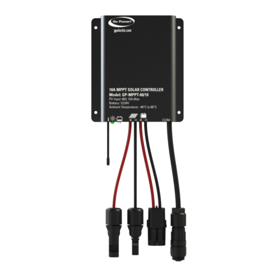
- Page 1 MPPT SOLAR CONTROLLER User Manual GP-MPPT-60-10 © 2022 Go Power! Worldwide Technical Support and Product Information gpelectric.com Go Power! | Dometic 201-710 Redbrick Street Victoria, BC, V8T 5J3 Tel: 1.866.247.6527 GP-MPPT-60-10_User Manual - RevB...
- Page 2 Congratulations on purchasing your Go Power! MPPT Solar Controller! Record the unit’s model and serial number below. It is much easier and quicker to record this information now at the pre-installation stage. Model Number: Serial Number: Date of Install: Battery Bank Information: (size, install date, battery type) Product Packaging Please safely store the packing the IC Series was delivered in or recycle the packaging components as outlined below:...
-
Page 3: Table Of Contents
CONTENTS 1. SAFETY PRECAUTIONS ................5 2. MAXIMUM POWER POINT TECHNOLOGY ..........6 3. OVERVIEW ....................8 4. FEATURES ....................8 5. WIRING ....................9 6. LED INDICATORS ..................10 7. PROTECTION ..................10 8. TECHNICAL SPECIFICATIONS ..............11 9. TROUBLESHOOTING .................12 10. WARRANTY ...................13 11. PRODUCT DIMENSIONS .................14 12. - Page 4 [page 4] | gpelectric.com...
-
Page 5: Safety Precautions
1. SAFETY PRECAUTIONS Important safety information is contained throughout this manual that should be carefully observed and followed. This information is presented using the following format. Warning / Caution: Result Description of condition leading to result SYMBOL The information is categorized in two ways: Warning: Bodily harm could occur if instructions are not explicitly followed. -
Page 6: Maximum Power Point Technology
2. MAXIMUM POWER POINT TECHNOLOGY Maximum Power Point Tracking (MPPT) is an advanced charging technology that more efficiently harvests power from solar panels in all conditions. It does this by continuously tracking the I-V curve of the solar array and modifying operating conditions to maximize output power. - Page 7 MAXIMUM POWER POINT TECHNOLOGY The graph below shows how the IV curve of a solar panel changes with varying temperatures. In partially shaded conditions there can also be multiple peaks in the P-V curve that can confuse an MPPT algorithm. Shown in the diagram below is a series string of solar panels.
-
Page 8: Overview
3. OVERVIEW Solar controllers, or solar charge controllers, continuously monitors the solar panel’s generating power and tracks the highest voltage and current values (VI) in real time, enabling the system to charge the battery to maximum power. It’s designed to be used in off-grid solar photovoltaic systems to coordinate operation of the solar panel, battery, and load, functioning as the core control unit in off-grid photovoltaic systems. -
Page 9: Wiring
5. WIRING Connection Order: Connect components to the charge controller in the sequence as shown above. Pay attention to the “+” and “-”. Please don’t insert the fuse or turn on the breaker during the installation. When disconnecting the system, reverse this order. The BATTERY LED will show green once the unit powers on. -
Page 10: Led Indicators
6. LED INDICATORS INDICATOR COLOR STATUS INSTRUCTION Green On Solid Not charging. PV connection normal but low voltage from PV, Green No PV voltage (night time) or PV connection problem Green Slowly Flashing Charging Green Fast Flashing PV over voltage Green On Solid Normal... -
Page 11: Technical Specifications
8. TECHNICAL SPECIFICATIONS Temperature sensor break down • If the temperature sensor is damaged or short-circuited, the controller will be reset to chargingn/discharging at the default tem- perature 25 ºC to prevent battery damage. High Voltage Transients • The controller is protected against small high voltage transients. In lightning prone areas, additional external suppression is rec- ommended. -
Page 12: Troubleshooting
9. TROUBLESHOOTING FAULTS POSSIBLE REASONS TROUBLESHOOTING LED Charging indicator turns off during Confirm that PV and battery wires are connected daytime when PV modules are in full PV array disconnection and secure sunlight Measure battery voltage with the multi-meter. No LED indicator Battery voltage may be less than 8.5V Min.8.5V can start up the controller Check if battery voltage is higher than OVD, and... -
Page 13: Warranty
10. WARRANTY 1. Go Power warrants the GP-MPPT-61/10 for a period of five (5) years from the date of shipment from its factory. This warranty is valid against defects in materials and workmanship for the five (5) year warranty period. It is not valid against defects resulting from, but not limited to: •... -
Page 14: Product Dimensions
11. PRODUCT DIMENSIONS 4.36 3.93 110.8 99.8 4.36 3.5 (X4) 3.5 (X4) 110.8 4.90 4.00 4.00 124.4 101.6 101.6 4.90 124.4 4.00 101.6 4.00 101.6 1.18 29.9 MARKETING CONTENT MARKETING CONTENT 1.18 29.9 MARKETING CONTENT UNLESS OTHERWISE SPECIFIED PROPRIETARY UNLESS OTHERWISE SPECIFIED VALTERRA DO NOT SCALE DRAWING DO NOT SCALE DRAWING... -
Page 15: Template
12. TEMPLATE 12. TEMPLATE gpelectric.com | [page 15] gpelectric.com | [page 15]... - Page 16 © 2022 Go Power! Worldwide Technical Support and Product Information gpelectric.com Go Power! | Dometic 201-710 Redbrick Street Victoria, BC, V8T 5J3 Tel: 1.866.247.6527 GP-MPPT-60-10_User Manual - RevB...
Need help?
Do you have a question about the Go Power! GP-MPPT-60-10 and is the answer not in the manual?
Questions and answers