Advertisement
Quick Links
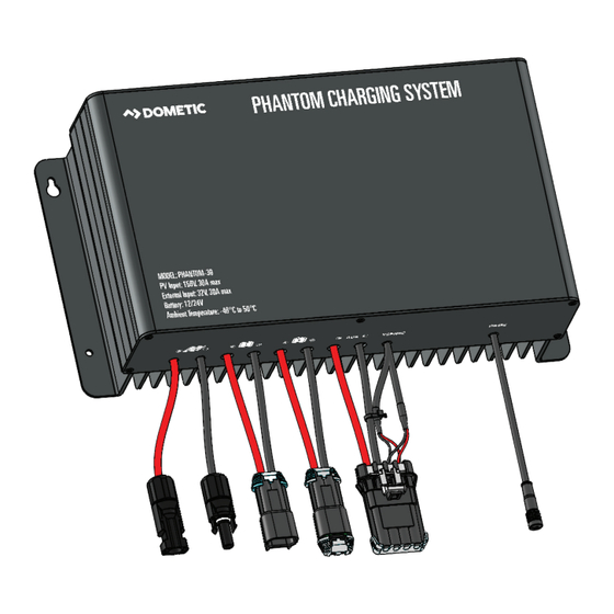
PHANTOM DUAL-SOURCE
SOLAR CONTROLLER
User Manual
GP-PHANTOM-30
© 2024 Go Power!
Worldwide Technical Support and Product Information
gopowersolar.com
Go Power! | Dometic
201-710 Redbrick Street Victoria, BC, V8T 5J3
Tel: 1.866.247.6527
83649REVA MANUAL_GP-PHANTOM-30
Advertisement

Subscribe to Our Youtube Channel
Related Manuals for Dometic Go Power! GP-PHANTOM-30


Summary of Contents for Dometic Go Power! GP-PHANTOM-30
- Page 1 PHANTOM DUAL-SOURCE SOLAR CONTROLLER User Manual GP-PHANTOM-30 © 2024 Go Power! Worldwide Technical Support and Product Information gopowersolar.com Go Power! | Dometic 201-710 Redbrick Street Victoria, BC, V8T 5J3 Tel: 1.866.247.6527 83649REVA MANUAL_GP-PHANTOM-30...
- Page 3 CONTENTS 1. INSTALLATION OVERVIEW ................5 1.1 INTRODUCTION ..................... 5 1.2 REGULATORY INFORMATION ................. 5 1.3 SPECIFICATIONS .................... 6 2. IMPORTANT SAFETY INSTRUCTIONS ............7 3. CHOOSING A LOCATION ................8 4. CHOOSING AN ARRAY ................8 5. INSTALLATION ..................8 5.1 TOOLS AND MATERIALS NEEDED ..............8 5.2 INSTRUCTIONS ....................
- Page 4 Congratulations on purchasing your Go Power! Phantom-30 Dual-Source Solar Controller! Record the unit’s model and serial number below. It is much easier and quicker to record this information now at the pre-installation stage. Model Number: Serial Number: Date of Install: Battery Bank Information: (size, install date, battery type) Product Packaging...
- Page 5 1. INSTALLATION OVERVIEW 1.1 INTRODUCTION The Phantom-30 Charging System is designed to increase the life and performance of up to two battery banks (12V or 24V). An example of two battery banks that you would want to charge would be your liftgate batteries (12V) and pallet jack batteries (24V).
- Page 6 INSTALLATION OVERVIEW 1.2 REGULATORY INFORMATION [page 6] | gopowersolar.com...
- Page 7 2. IMPORTANT SAFETY INSTRUCTIONS Electricity can be very dangerous. Installation should be performed Disconnect all power sources only by a licensed electrician or qualified personnel. Observe all safety precautions of the battery manufacturer when Battery and wiring safety handling or working around batteries. When charging, batteries produce hydrogen gas, which is highly explosive.
- Page 8 3. PLANNING FOR LOCATIONS AND HARNESSING The Phantom-30 is designed to be mounted in any orientation. Allow at least 2in (5cm) of space around Phantom-30 for cooling. Install on non-flammable surface. WHITE (Ground) BLUE (AUX & ABS Power) Phantom-30 Make sure there is room for the Phantom-30 to be mounted close to the 12V battery bank (e.g. near or on the liftgate battery box). If charging a pallet jack, move the pallet jack inside the truck/trailer to a suitable location for charging when stored.
- Page 9 4. INSTALLATION Solar Panels Remove the thin protective layer from the top surface of the panel. Peel back a small portion (~5”) of the nonstick layer of the adhesive backing tape (Figure 1) on the top or bottom of the solar module. Place the side of the panel with the exposed adhesive in the desired panel location.
- Page 10 INSTALLATION Phantom-30 Install the Phantom-30 in your selected location using the locking machine screws (blunt end). (Figure 6 and 7) The self-tapping screws are designed for use with sheet metal. Alternate fasteners may be used for increased mounting strength or for other wall compositions. Route the Liftgate Battery Harness (83255) from the Battery 1 connector on the Phantom-30 to the liftgate batteries.
- Page 11 5. TESTING THE PHANTOM-30 CHARGING SYSTEM Ensure the solar panels are charging the batteries: • Ensure the solar panels are in the sunlight (opaque material removed). • Attach a clamp-on ammeter around the positive wire of the Liftgate Battery Harness (83255) between the Phantom-30 and the liftgate batteries.
- Page 12 [page 12] | gopowersolar.com...
- Page 13 6. WARRANTY Go Power! warrants the Phantom-30 for a period of five (5) years from the date of shipment from its factory. This warranty is valid against defects in materials and workmanship for the five (5) year warranty period. It is not valid against defects resulting from, but not limited to: •...
- Page 14 © 2024 Go Power! Worldwide Technical Support and Product Information gopowersolar.com Go Power! | Dometic 201-710 Redbrick Street Victoria, BC, V8T 5J3 Tel: 1.866.247.6527 83649REVA - MANUAL_GP-Phantom-30...
Need help?
Do you have a question about the Go Power! GP-PHANTOM-30 and is the answer not in the manual?
Questions and answers