Advertisement
Quick Links
Installation and Instruction Manual
HIGH BAY DUAL SENSE SENSOR
1. Technical Specifications
Product type
Tri-level control dual sense sensor
Operating voltage
220-240VAC 50/60Hz
800VA(Capacitive)
Rated load
1000W(Resistive)
Power consumption
< 1W
o
Detection angle
360
Max installation height:15m (forklift)/12m (human)
Detection area (Max.)*
Max detection range:
HF: Ø = 24m (forklift)/14m (human)
PIR: Ø = 24m (forklift)/20m (human)
Detection range
10% / 50% / 75% / 100%
Hold time
2s / 30s / 1min / 5min / 10min / 15min / 20min / 30min
Stand-by time
0s / 10s / 1min / 5min / 10min / 30min / 1h / + ∞
Stand-by dimming level
10% / 20% / 30% / 50%
Daylight threshold
2 ~ 500Lux, Disable
Warmming up time
30s
o
o
Operating temperature
-20
C ~ +50
C
IP rating
IP65
Sensor mode
HF, PIR, HF+PIR, HF / PIR
2. Rotary Switch Settings
A rotary switch is built inside the sensor for
Rotary switch preset (Please
scene selection / fast programming. Total of
see the location in 2. Installation)
16 channels available:
Detection
Hold
Stand-by
Stand-by
Channel
range
time
time
dimming level
0
100%
5s
10s
10%
1
100%
1min
5min
10%
2
100%
5min
10min
10%
3
100%
5min
30min
10%
4
100%
5min
0s
Disable
5
100%
5min
+∞
10%
6
100%
5min
+∞
30%
7
100%
10min
10min
10%
8
100%
10min
30min
10%
9
100%
10min
+∞
10%
A
100%
10min
+∞
30%
B
75%
10min
+∞
10%
C
50%
10min
+∞
10%
D
100%
30min
+∞
10%
E
100%
30min
+∞
30%
F
100%
5s
10s
10%
Note: settings can also be changed by remote control HRC-11. The last action controls.
3. Functions
3.1 Tri-level Control (Corridor Function)
Hytronik builds this function inside the motion sensor to achieve tri-level control, for some areas it requires
a light change notice before switch-off.
It offers 3 levels of light: 100%-->dimmed light-->off; and 2 periods of selectable waiting time: motion
hold-time and stand-by period; Selectable daylight threshold and freedom of detection area.
3.2 Lux Off Function
The built-in daylight sensor can read ambient natural light and switch off the fixture automatically
whenever artificial light is unnecessary (natural light lux level exceeds daylight threshold).
Note: if the stand-by time is preset at "+∞", the fixture never switches off even when natural light
is sufficient.
3.3 Load Indication
The light will flash ONCE rapidly after receiving the command from the remote controller.
Note: There is no load indication (the light will not flash) when button ON/OFF, POWER 100%
or POWER 80% is pressed.
4. Installation
Warnings:
1. Installation of the sensor involves connecting it to the mains supply. This work must be
carried out by a specialist in accordance with electrotechnical regulations.
2. Disconnect power supply before installing.
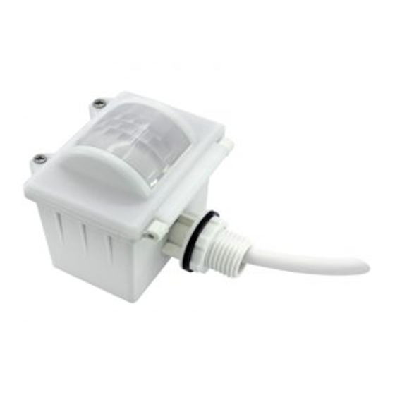
A. Ceiling mount
Infrared receiver
LED indicator
Rotary switch for programing
Daylight sensor
PIR
Sensor module
Cable entry
Installation rack
B. Screw to the Luminaire by conduit
Daylight
threshold
Infrared receiver
LED indicator
Disable
Rotary switch for programing
Daylight sensor
2Lux
PIR
10Lux
30Lux
10Lux
30Lux
Disable
Sensor module
2Lux
Cable entry
10Lux
30Lux
Disable
30Lux
10Lux
50Lux
C. Attach to the shade by clamp
Disable
2Lux
Rotary switch for programing
LED indicator
Infrared receiver
Daylight sensor
Angle adjustment
Luminaire clamp
PIR
Sensor module
Note:We recommend the mounting distance between sensor to sensor
should be more than 2m to prevent sensors from false-triggering.
5. Wiring Diagram
L
HIM31
N
4.1
66.6
6. Three Options for PIR Lens and Detection Patterns
81.5
* For single person walking across, the detection range is reduced by 1/3.
1
59.6
0.825"
Detection pattern for forklift
43
66.6
15m(forklift)
89.9
PIR detection: Ø = 24m (max.)
HF detection: Ø = 24m (max.)
Detection pattern for human
15
4.5
28.5
66.6
96.8
163.2
12m(human)
HF detection: Ø = 14m (max.)
PIR detection: Ø = 20m (max.)
HIM31-20230620-A1
Brown
Blue
Grey
L
Red
LED driver
N
Black
1-10V+
1-10V-
HIM31
———This product should be installed by a qualified electrician.
(End user can choose the suitable lens in real application for various requirements)
2
PIR
PIR
HF
HF
15m(forklift)
PIR detection: Ø = 24m (max.)
HF detection: Ø = 24m (max.)
PIR
PIR
HF
HF
12m(human)
HF detection: Ø = 14m (max.)
PIR detection: Ø = 20m (max.)
3
PIR
HF
15m(forklift)
PIR & HF: max. 24m
PIR detection: Ø = 24m (max.)
HF detection: Ø = 24m (max.)
PIR
HF
12m(human)
HF : max. 14m
PIR: max. 20m
HF detection: Ø = 14m (max.)
PIR detection: Ø = 20m (max.)
HIM31-20230620-A1
Advertisement

Related Manuals for Hytronik HIM31


Summary of Contents for Hytronik HIM31
- Page 1 163.2 12m(human) 12m(human) Hytronik builds this function inside the motion sensor to achieve tri-level control, for some areas it requires 12m(human) a light change notice before switch-off. It offers 3 levels of light: 100%-->dimmed light-->off; and 2 periods of selectable waiting time: motion Sensor module hold-time and stand-by period;...
- Page 2 Press button “RX STBY%”, the light(s) oes to pre-set stand-by dimming level directly. 1.Press button “Shift” ,the red LED on. HF+PIR 2. Choose one of the four detecion mode “HF only”, “PIR only”, “HF& PIR” or“ HF/PIR”. HF/ PIR HIM31-20230620-A1 HIM31-20230620-A1...
- Page 3 9. Additional Information / Documents 1. Regarding precautions for microwave sensor installation and operation, please kindly refer to www.hytronik.com/download ->knowledge ->Microwave Sensors - Precautions for Product Installation and Operation 2. Regarding precautions for PIR sensor installation and operation, please kindly refer to www.hytronik.com/download ->knowledge ->PIR Sensors - Precautions for Product Installation and Operation 3.
Need help?
Do you have a question about the HIM31 and is the answer not in the manual?
Questions and answers