Advertisement
Quick Links
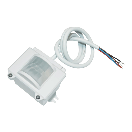
HIGH BAY DUAL SENSE SENSOR HIM34
1. Technical Specifications
Product type
High bay dual sense DALI sensor (Daylight harvest)
Operating voltage
220-240VAC 50/60Hz
Switched power
Maximum 20pcs DALI devices Maximum 40mA
Power consumption
< 1W
o
Detection angle
360
Detection area (DxH)
18 x 15m (Maximum)
Detection range
10% / 50% / 75% / 100%
Hold time
2s / 30s / 1min / 5min / 10min / 15min / 20min / 30min
Stand-by time
0s / 10s / 1min / 5min / 10min / 30min / 1h / + ∞
Stand-by dimming level
10% / 20% / 30% / 50%
Daylight threshold
50 ~ 500Lux , Disable
Warmming-up time
30s
o
Operating temperature
-35
C ~ +50
IP rating
IP65
Sensor mode
HF, PIR, HF+PIR, HF / PIR
3. Rotary Switch Settings
A rotary switch is built inside the sensor for
scene selection / fast programming. Total
16 channels available:
Detection
Hold
Channel
range
time
0
100%
5s
1
100%
1min
2
100%
5min
3
100%
5min
4
100%
5min
5
100%
5min
6
100%
10min
7
100%
10min
8
100%
10min
9
100%
10min
A
100%
20min
B
100%
20min
C
100%
30min
D
100%
30min
E
100%
30min
F
100%
5s
Note: settings can also be changed by remote control HRC-11. The last action controls.
4. Functions
4.1 Daylight Harvest (Daylight Regulating)
Daylight sensor measures the available natural light of the surrounding, calculates how much electrical
light is needed to reach the total lux expected. The demand is given to the LED driver by DALI signal, so as
to deliver the needed amount of electric light.
Light level
Energy Saving Zone
0
Installation and Instruction Manual
o
C
Rotary switch preset (Please
see the location in 2. Installation)
Stand-by
Stand-by
Daylight
time
dimming level
threshold
10s
10%
Disable
5min
10%
50Lux
10min
10%
50Lux
+∞
10%
75Lux
+∞
10%
100Lux
+∞
30%
200Lux
30min
10%
50Lux
+∞
10%
75Lux
+∞
10%
100Lux
+∞
30%
200Lux
1h
10%
100Lux
+∞
30%
200Lux
+∞
10%
100Lux
+∞
30%
200Lux
+∞
50%
400Lux
10s
10%
100Lux
Hold time
Normal Electric Light
Daylight controlled light
Stand-by time
Natural light
24
Time (hrs)
2. Installation
Warnings:
1. Installation of the sensor involves connecting it to the mains supply. This work must be
carried out by a specialist in accordance with electrotechnical regulations.
2. Disconnect power supply before installing.
A. Ceiling mount
Infrared receiver
LED indicator
Rotary switch for programing
Photocell
PIR
Sensor module
Installation rack
B. Screw to the Luminaire by conduit
Infrared receiver
LED indicator
Rotary switch for programing
Photocell
PIR
Sensor module
C. Attach to the shade by clamp
Infrared receiver
LED indicator
Rotary switch for programing
Photocell
Angle adjustment
PIR
Sensor module
4.2 Lux Off Function
The built-in daylight sensor can read ambient natural light and switch off the fixture automatically
whenever artificial light is not required (natural light lux level exceeds daylight threshold).
Note: if the stand-by time is preset at "+∞", the fixture never switches off even when natural light
is sufficient.
4.3 Load Indication
The light will flash ONCE rapidly after receiving the command from the remote controller.
Note: There is no load indication (the light will not flash) when button ON/OFF, POWER 100%
or POWER 80% is pressed.
5. Wiring Diagram
L
N
Brown
Blue
Red
Black
HIM34
4.1
66.6
81.5
Cable entry
59.6
43
66.6
89.9
Cable entry
53
Luminaire clamp
80
66.6
146.6
L
LED
Driver
N
+
DALI
-
DALI
HIM34-20180525-A3
0.825"
Advertisement

Subscribe to Our Youtube Channel
Related Manuals for Hytronik HIM34


Summary of Contents for Hytronik HIM34
-
Page 1: Wiring Diagram
HIGH BAY DUAL SENSE SENSOR HIM34 Installation and Instruction Manual 1. Technical Specifications 2. Installation Product type High bay dual sense DALI sensor (Daylight harvest) Warnings: 1. Installation of the sensor involves connecting it to the mains supply. This work must be... - Page 2 To set daylight sensor at 100Lux / 300 Lux / 500Lux, press button Shift at first. Hytronik Industrial Ltd. | www.hytronik.com 3rd Floor, block C, complex building, 155#, Bai'gang road south, Bai'gang village, Xiao Jin Kou town, Huicheng district, Huizhou 516023...
Need help?
Do you have a question about the HIM34 and is the answer not in the manual?
Questions and answers