Table of Contents
Advertisement
Quick Links
IP65 High Bay Dual Sense Sensor
HIM34
HF and PIR, Daylight Harvest for Independent DALI
Technical Data
Input Characteristics
Model No.
Mains voltage
Stand-by power
Switched power
Warming-up
Safety and EMC
EMC standard (EMC)
Safety standard (LVD)
Radio Equipment (RED)
Certi cation
Mechanical Structures and Installations
For more details, please refer to user manual.
A. Ceiling mount
Subject to change without notice.
HIM34
120~277VAC 50/60Hz
<1W
Max. 20pcs devices, 40mA
30s
EN55015, EN61000
EN60669, AS/NZS60669
EN300440, EN301489-1,
EN62479
Semko, CB, CE , EMC, RED, SAA
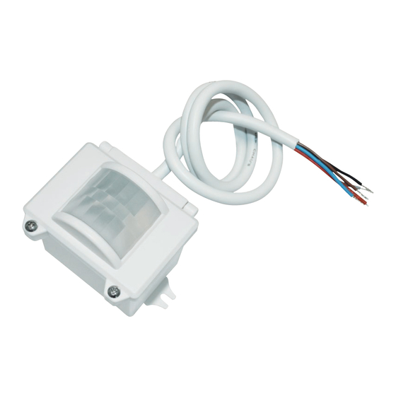
LED indicator
Daylight sensor
PIR
Sensor module
Installation rack
TM
Sensor Data
Model No.
Sensor principle
High Frequency (microwave), PIR
Operation frequency
Transmission power
Sensor mode
4 modes: PIR, HF, PIR+HF, PIR/HF
Detection angle
Environment
Operation temperature
IP rating
RED
Infrared receiver
Rotary switch for programing
Cable entry
Edition: 26 Feb. 2020
HIM34
5.8GHz +/- 75MHz (HF)
<0.2mW (HF)
Max. ( O x H) 18m x 15m
O
360
O
O
Ta: -20
C ~ +50
C
IP65
IP65
4.1
66.6
81.5
Ver. A0
Page 1/6
Advertisement
Table of Contents

Related Manuals for Hytronik HIM34


Summary of Contents for Hytronik HIM34
- Page 1 IP65 High Bay Dual Sense Sensor HIM34 HF and PIR, Daylight Harvest for Independent DALI Technical Data Sensor Data Input Characteristics Model No. Model No. HIM34 HIM34 Sensor principle High Frequency (microwave), PIR Mains voltage 120~277VAC 50/60Hz Stand-by power Operation frequency <1W...
- Page 2 B. Screw to the Luminaire by conduit 59.6 0.825” Infrared receiver LED indicator Rotary switch for programing Photocell 66.6 89.9 Sensor module Cable entry C. Attach to the shade by clamp Infrared receiver LED indicator Rotary switch for programing Photocell Angle adjustment 28.5 Luminaire clamp...
- Page 3 Wiring Diagram Brown Blue Driver Black DALI + DALI HIM34 Subject to change without notice. Edition: 26 Feb. 2020 Ver. A0 Page 3/6...
- Page 4 Detection Pattern End user can choose the suitable PIR lens in real application to ful ll various requirements. Three options are offered for selection: PIR detection: L x W x H:18 x 5 x 15m (max.) PIR detection: L x W x H:5 x 18 x 15m (max.) PIR detection: H x D:15 x 18m (max.) HF detection: H x D:15 x 14m (max.) HF detection: H x D:15 x 14m (max.
- Page 5 Settings (Remote Control HRC-11) Permanent ON/OFF function Press button “ON/OFF” to select permanent ON or permanent OFF mode. * Press button “AUTO”, “RESET” to quit this mode. The mode will change to AUTO Mode after power failure. Reset Settings Press button “RESET”, all settings go back to rotary switch settings. Shift Button Press button “Shift”, the LED on the top left corner is on to indicate mode selection.
- Page 6 Additional Information / Documents 1. Regarding precautions for microwave sensor installation and operation, please kindly refer to www.hytronik.com/download ->knowledge ->Microwave Sensors - Precautions for Product Installation and Operation 2. Regarding precautions for PIR sensor installation and operation, please kindly refer to www.hytronik.com/download ->knowledge ->PIR Sensors - Precautions for Product Installation and Operation...
Need help?
Do you have a question about the HIM34 and is the answer not in the manual?
Questions and answers