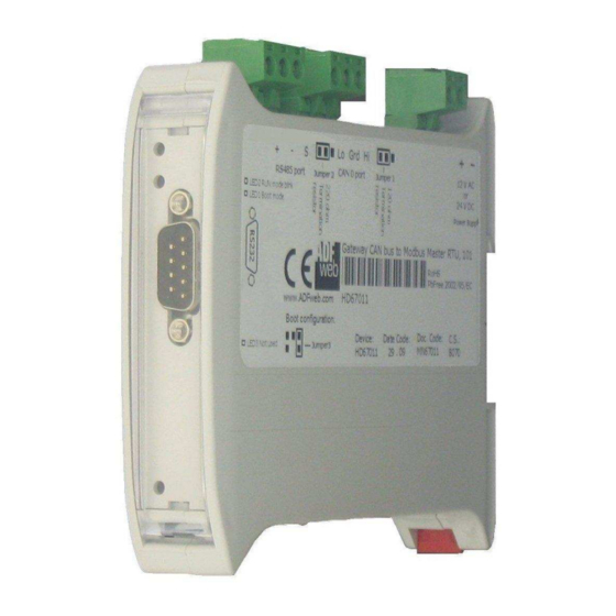
Summary of Contents for ADF Web HD67146-A1
- Page 2 User Manual Document code: MN67146_ENG Revision 1.001 Page 1 of 18 Industrial Electronic Devices User Manual Revision 1.001 English (Order Code: HD67146)A1) for Website information: www.adfweb.com/?Product=HD67146 for Price information: For others Modbus devices, see also the following links: www.adfweb.com/?Price=HD67146)A1 www.adfweb.com?Product=HD67141 www.adfweb.com?Product=HD67506 www.adfweb.com?Product=HD67011 Very easy to configure...
- Page 3 User Manual Document code: MN67146_ENG Revision 1.001 Page 2 of 18 Industrial Electronic Devices Dear customer, we thank you for your attention and we remind you that Page you need to check that the following document is: INDEX UPDATED DOCUMENTATION Updated;...
- Page 4 User Manual Document code: MN67146_ENG Revision 1.001 Page 3 of 18 Industrial Electronic Devices %"$ / * " " * #" To ensure safe operation, the device must be operated according to the instructions in the manual. When using the device are required for each individual application, legal and safety regulation.
- Page 5 User Manual Document code: MN67146_ENG Revision 1.001 Page 4 of 18 Industrial Electronic Devices !* # Used to communicate with some Modbus slave from two Modbus Master. " # $ %...
- Page 6 User Manual Document code: MN67146_ENG Revision 1.001 Page 5 of 18 Industrial Electronic Devices &' * +, $+- " # $ %...
- Page 7 User Manual Document code: MN67146_ENG Revision 1.001 Page 6 of 18 Industrial Electronic Devices 1 " "$ The configurable “Modbus Slave / Modbus Slave ) Converter” has the following characteristics: Galvanic isolation between the two Modbus ports. Mountable on 35mm Rail DIN; Power Supply 8...19V AC or 8...35V DC;...
- Page 8 User Manual Document code: MN67146_ENG Revision 1.001 Page 7 of 18 Industrial Electronic Devices !#, " %!!*/ The devices can be powered between a wide range of tensions. For more details see the two tables below. 1 34563 Consumption at 24V DC: HD67146)A1 ;...
- Page 9 User Manual Document code: MN67146_ENG Revision 1.001 Page 8 of 18 Industrial Electronic Devices The device has got two functions mode depending of the position of the Jumper 3 (Boot Jumper): The first, without Jumper 3, is used for the normal working of the device. The second, with Jumper 3 in position Boot Mode, is used for upload the Project/Firmware.
- Page 10 User Manual Document code: MN67146_ENG Revision 1.001 Page 9 of 18 Industrial Electronic Devices The device has got three LEDs that are used to give information of the functioning status. The various meanings of the LEDs are described in the table below. Blinks slowly (~1Hz) 1: LED1 (green) Blinks quickly...
- Page 11 User Manual Document code: MN67146_ENG Revision 1.001 Page 10 of 18 Industrial Electronic Devices " 67: terminate RS485 line with 220R resistor necessary to put the jumper near terminal block, like in figure. The RS485 0 is Isolated. The maximum length of the cable should be 1200m (4000 feet). Here some codes of cables: Belden: p/n 8132 ) 2x 28AWG stranded twisted pairs conductor + foil shield + braid shield;...
- Page 12 User Manual Document code: MN67146_ENG Revision 1.001 Page 11 of 18 Industrial Electronic Devices $-%" #" ,34563 To configure the Converter, use the available software that runs with Windows, called SW67147. downloadable site www.adfweb.com and its operation is described in this document. ) )! ) 0.
- Page 13 User Manual Document code: MN67146_ENG Revision 1.001 Page 12 of 18 Industrial Electronic Devices This section defines the fundamental communication parameter of three ports Modbus. By pressing the “ ” button from the main window for SW67146 (Fig. 2) the window “Set Communication” appears (Fig.
- Page 14 User Manual Document code: MN67146_ENG Revision 1.001 Page 13 of 18 Industrial Electronic Devices By pressing the “%+ ” button it is possible to load the created Configuration into the device; and also the Firmware, if is necessary. In order to load the parameters or update the firmware in the device, follow these instructions: Turn off the Device;...
- Page 15 User Manual Document code: MN67146_ENG Revision 1.001 Page 14 of 18 Industrial Electronic Devices Note: When you install a new version of the software it is better if the first time you do the update of the Firmware in the HD67146)A1. Note: When you receive the device, for the first time, you have to update also the Firmware in the HD67146)A1 devices.
- Page 16 User Manual Document code: MN67146_ENG Revision 1.001 Page 15 of 18 Industrial Electronic Devices &' * +, $+- " # $ %...
- Page 17 User Manual Document code: MN67146_ENG Revision 1.001 Page 16 of 18 Industrial Electronic Devices #" "$ - $ #" The ordering part number is formed by a valid combination of the following: 1 34563 ? 1: Removable 5mm Screw Terminal A: 1M, 35mm DIN Rail mounting HD67146: Modbus Master / Modbus MultiSlave ) Converter Order Code: 1 34'563...
- Page 18 User Manual Document code: MN67146_ENG Revision 1.001 Page 17 of 18 Industrial Electronic Devices " All technical content within this document can be modified without notice. The content of the document content is a recurring audit. For losses due to fire, earthquake, third party access or other accidents, or intentional or accidental abuse, misuse, or use under abnormal conditions repairs are charged to the user.
- Page 19 User Manual Document code: MN67146_ENG Revision 1.001 Page 18 of 18 Industrial Electronic Devices , "" %!!#" For fast and easy technical support for your ADFweb.com SRL products, consult our internet support at www.adfweb.com. Otherwise contact us at the address support@adfweb.com "...


Need help?
Do you have a question about the HD67146-A1 and is the answer not in the manual?
Questions and answers