Table of Contents
Advertisement
Quick Links
Advertisement
Table of Contents
Troubleshooting

Related Manuals for Miller Bobcat 260 Diesel


Summary of Contents for Miller Bobcat 260 Diesel
- Page 1 OM-286506D 2020-10 Processes Stick (SMAW) Welding MIG (GMAW) Welding Flux Cored (FCAW) Welding TIG (GTAW) Welding Description Engine Driven Welder/Generator Bobcat 260 Diesel ™ OWNER’S MANUAL For product information, Owner’s Manual translations, and more, visit www.MillerWelds.com...
- Page 2 We know you don’t have time to do it any other way. That’s why when Niels Miller first started building arc welders in 1929, he made sure his products offered long-lasting value and superior quality.
-
Page 3: Table Of Contents
TABLE OF CONTENTS SECTION 1 – SAFETY PRECAUTIONS – READ BEFORE USING..............1 Symbol Usage . - Page 4 TABLE OF CONTENTS SECTION 7 – OPERATING AUXILIARY EQUIPMENT................36 Generator Power Receptacles .
-
Page 5: Section 1 - Safety Precautions - Read Before Using
SECTION 1 – SAFETY PRECAUTIONS – READ BEFORE USING Protect yourself and others from injury—read, follow, and save these important safety precautions and operating instructions. 1-1. Symbol Usage DANGER! – Indicates a hazardous situation which, if not avoided, will result in death or serious injury. The possible hazards are shown in the adjoining symbols or explained in the text. - Page 6 HOT PARTS can burn. WELDING can cause fire or explosion. � Do not touch hot parts bare handed. � Allow cooling period before working on equipment. Welding on closed containers, such as tanks, drums, or pipes, can cause them to blow up. �...
-
Page 7: Engine Hazards
� Never weld on a pressurized cylinder — explosion will result. CYLINDERS can explode if � Use only correct compressed gas cylinders, regulators, hoses, damaged. and fittings designed for the specific application; maintain them Compressed gas cylinders contain gas under high and associated parts in good condition. -
Page 8: Compressed Air Hazards
1-4. Compressed Air Hazards � Reinstall doors, panels, covers, or guards when servicing is fin- COMPRESSED AIR EQUIPMENT can ished and before starting unit. injure or kill. � If ANY air is injected into the skin or body seek medical help immediately. - Page 9 � Follow the guidelines in the Applications Manual for the Revised HIGH PRESSURE FLUIDS can injure NIOSH Lifting Equation (Publication No. 94-110) when manually or kill. lifting heavy parts or equipment. � Engine fuel system components can be under high OVERHEATING can damage motors.
-
Page 10: California Proposition 65 Warnings
� To reduce possible interference, keep weld cables as short as ARC WELDING can cause possible, close together, and down low, such as on the floor. interference. � Locate welding operation 100 meters from any sensitive electronic equipment. � Electromagnetic energy can interfere with sensitive electronic equipment such as microprocessors, �... -
Page 11: Section 2 - Consignes De Sécurité - Lire Avant Utilisation
SECTION 2 – CONSIGNES DE SÉCURITÉ - LIRE AVANT UTILISATION Pour écarter les risques de blessure pour vous-même et pour autrui — lire, appliquer et ranger en lieu sûr ces consignes relatives aux précautions de sécurité et au mode opératoire. 2-1. - Page 12 � N’utiliser qu’un matériel en bon état. Réparer ou remplacer sur-le- � Ne pas souder dans des endroits situés à proximité d’opérations champ les pièces endommagées. Entretenir l’appareil conformé- de dégraissage, de nettoyage ou de pulvérisation. La chaleur et ment à ce manuel. les rayons de l’arc peuvent réagir en présence de vapeurs et for- mer des gaz hautement toxiques et irritants.
-
Page 13: Dangers Existant En Relation Avec Le Moteur
� Le soudage effectué sur un plafond, plancher, paroi ou séparation Les CHAMPS peut déclencher un incendie de l’autre côté. ÉLECTROMAGNÉTIQUES (CEM) � Ne pas couper ou souder des jantes ou des roues. Les pneus peu- peuvent affecter les implants vent exploser s’ils sont chauffés. -
Page 14: Dangers Liés À L'air Comprimé
� Ne pas faire le plein en fumant ou proche d’une source d’étincelles � Ne pas toucher aux pièces chaudes, utiliser les outils recomman- ou d’une flamme nue. dés et porter des gants de soudage et des vêtements épais pour éviter les brûlures. -
Page 15: Symboles De Dangers Supplémentaires En Relation Avec L'installation, Le Fonctionnement Et La Maintenance
MÉTAL CHAUD provenant du Une PRESSION D’AIR RÉSIDUELLE découpage ou du gougeage à l’arc ET DES FLEXIBLES QUI FOUETTENT risque de provoquer un incendie ou risquent de provoquer des une explosion. blessures. � Détendre la pression pneumatique des outils et circuits avant �... - Page 16 � Suivre les consignes du Manuel des applications pour l’équation � Ne charger que des batteries plomb-acide. Ne pas utiliser le char- de levage NIOSH révisée (Publication Nº94-110) lors du levage geur de batterie pour alimenter un autre circuit électrique basse manuelle de pièces ou équipements lourds.
-
Page 17: Proposition Californienne 65 Avertissements
� Effectuer l’installation, l’entretien et toute intervention selon les LE SOUDAGE À L’ARC risque de manuels d’utilisateurs, les normes nationales, provinciales et de provoquer des interférences. l’industrie, ainsi que les codes municipaux. � L’énergie électromagnétique risque de provoquer LE RAYONNEMENT HAUTE des interférences pour l’équipement électronique FRÉQUENCE (H.F.) risque de sensible tel que les ordinateurs et l’équipement... -
Page 18: Informations Relatives Aux Cem
2-8. Informations relatives aux CEM 3. Ne pas courber et ne pas entourer les câbles autour de votre Le courant électrique qui traverse tout conducteur génère des corps. champs électromagnétiques (CEM) à certains endroits. Le courant is- su d’un soudage à l’arc (et de procédés connexes, y compris le sou- 4. -
Page 19: Section 3 - Definitions
Safe8 For single phase operation, insulate and isolate red conducto � Include extra length in grounding conductor and connect grou Complete Parts List is available at www.MillerWelds.com conductor first. Connect black, white, and red wires (L1, L2, L Never use generator inside a home or garage, even if doors a SECTION 3 –... - Page 20 � Complete Parts List is available at www.MillerWelds.com Shielded Metal Arc Battery (Engine) Engine Welding (SMAW) Gas Metal Arc Fuel Glow Plug Welding (GMAW) Engine Oil Welding Hour Meter Gas Tungsten Arc Check Valve Welding (GTAW) / Belt Drive Clearance Tungsten Inert Gas (TIG) Welding Single Phase...
-
Page 21: Section 4 - Specifications
Information About Default Weld Parameters And Settings NOTICE – Each welding application is unique. Although certain Miller Electric products are designed to determine and default to certain typical welding parameters and settings based upon specific and relatively limited application variables input by the end user, such default settings are for reference purposes only;... -
Page 22: Dimensions, Weights, And Operating Angles
� Complete Parts List is available at www.MillerWelds.com 4-7. Dimensions, Weights, And Operating Angles Do not exceed tilt angles or engine could be damaged or unit could tip. Do not move or operate unit where it could tip. Weight: 638 lb (289 kg) Lifting Eye Weight Rating: 1250 lb (567 kg) Support Assembly Dimensions 259 701 / 259 702... -
Page 23: Duty Cycle And Overheating
� Complete Parts List is available at www.MillerWelds.com 4-8. Duty Cycle And Overheating 1 100% Duty Cycle Duty cycle is the percentage of 10 minutes that unit can weld at rated load without overheating. � This unit is rated at 260 amperes for continuous welding. -
Page 24: Volt-Ampere Curves
� Complete Parts List is available at www.MillerWelds.com 4-9. Volt-Ampere Curves The volt-ampere curve shows the minimum CC/AC Mode and maximum voltage and amperage output capabilities of the welder/generator. Curves of all other settings fall between the curves shown. CC/DC Mode CV/DC Mode OM-286506 Page 20... -
Page 25: 4-10. Generator Power Curve
� Complete Parts List is available at www.MillerWelds.com 4-10. Generator Power Curve The generator power curve shows the gener- ator power in amperes available at the receptacles. Amps 4-11. Fuel Consumption On a typical job using 1/8 in. 7018 electrodes (125 amps, 20% duty cycle), expect about 24 hours of operation per fuel fill. -
Page 26: Section 5 - Installation
� Complete Parts List is available at www.MillerWelds.com 1-1. Installing Welder/Generator SECTION 5 – INSTALLATION 1-1. Installing Welder/Generator 5-1. Installing Welder/Generator Complete Parts List available at www.MillerWelds.com Do not move or operate unit where Movement it could tip. Do not lift unit from end. Do not weld on base. -
Page 27: Grounding Generator To Truck Or Trailer Frame
� Complete Parts List is available at www.MillerWelds.com 5-2. Grounding Generator to Truck or Trailer Frame 1-1. Grounding Generator To Truck Or Trailer Frame GND/PE Bed liners, shipping skids, and 1 Equipment Grounding Terminal Always ground generator frame to some running gear insulate the Front Panel) vehicle frame to prevent electric welding generator from the vehicle... -
Page 28: Connecting The Battery
259 703 � Complete Parts List is available at www.MillerWelds.com 5-4. Connecting The Battery 259 707 / Ref. S-0756-D 3/8, 1/2 in. Connect negative (–) cable last. (+) cable to the positive (+) battery ter- � Never use a quick battery charger to ps head wrench crescent wrench... - Page 29 OM-286506 Page 25...
-
Page 30: Engine Prestart Checks And Overview
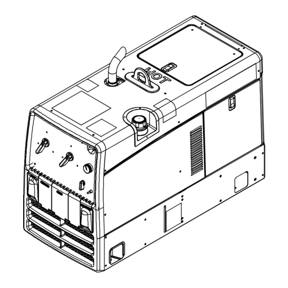
� Complete Parts List is available at www.MillerWelds.com 5-5. Engine Prestart Checks And Overview 804 249-A / 804 250-A OM-258413 Page 8 OM-286506 Page 26... - Page 31 � Complete Parts List is available at www.MillerWelds.com 1 Generator Power Receptacles (see Section 7-1) 2 Weld Output Terminals (see Section 5-7) 3 Operator Controls (see Section 6-1) 4 Fuel Gauge/Maintenance Display 5 Fuel Filler Cap 6 Exhaust Pipe 7 Engine Maintenance Label 8 Radiator Cap 9 Water Bypass Hose 10 Oil Fill Cap...
-
Page 32: Selecting Cable Sizes
� Complete Parts List is available at www.MillerWelds.com 5-6. Selecting Cable Sizes* NOTICE – The Total Cable Length in Weld Circuit (see table below) is the combined length of both weld cables. For example, if the power source is 100 ft (30 m) from the workpiece, the total cable length in the weld circuit is 200 ft (2 cables x 100 ft). Use the 200 ft (60 m) column to determine cable size. -
Page 33: Connecting Weld Output Cables
Complete Parts List available at www.MillerWelds.com � Complete Parts List is available at www.MillerWelds.com 5-8. Connecting Weld Output Cables Stop engine. Failure to properly connect weld cables may cause excessive heat and start a fire, or damage your machine. � Do not place anything between weld cable terminal and copper bar. -
Page 34: Section 6 - Operation
� Complete Parts List is available at www.MillerWelds.com SECTION 6 – OPERATION 6-1. Front Panel Controls 5 Coarse Range Switch NOTICE – Disconnect equipment from auxil- Glow Plug Time iary power receptacles during start-up and NOTICE – Do not switch while welding. 70°F (21°C) 0 seconds shutdown. -
Page 35: Using Wireless Remote
� Complete Parts List is available at www.MillerWelds.com 6-2. Using Wireless Remote Place Engine Control switch in Off position when welder/generator is not in use to prevent unexpected starting. Check that all doors, panels, cov- ers, and guards are closed and se- curely in place before starting. -
Page 36: Typical Stick Welding Connections And Control Settings
� Set Weld Process Selector switch to + Stick position. � Set Coarse Range switch to 60-160 (1/ 8”) position. � Set Fine control at 7 or higher for best results. � Miller recommends Hobart filler metals. 3/4 in. ps head wrench crescent wrench OM-286506 Page 32... -
Page 37: Typical Mig Welding Connections And Settings
� Complete Parts List is available at www.MillerWelds.com 6-4. Typical MIG Welding Connections And Settings Stop engine. � This section provides general guide- lines and may not suit all applications. 1 Work Clamp 2 Wire Feeder 3 MIG Gun 4 Gun Trigger Plug 5 Voltage Sensing Clamp 6 Gas Cylinder: 75/25 Argon/CO... -
Page 38: Typical Mig Connections And Settings Using Weld Control And Spoolgun
Connect AC power cord (item 12) to 120 volt increase/decrease arc length. AC receptacle on welder/generator. 12 Input Power Cord � 13 Unused Contactor Terminal Connect gas hose from spoolgun to regula- Miller recommends Hobart filler clamp wirecutter frontcutter 14 Work tor on Argon bottle. -
Page 39: Fuel/Hour Gauge Descriptions
� Complete Parts List is available at www.MillerWelds.com 6-6. Fuel/Hour Gauge Descriptions OM-286506 Page 35... -
Page 40: Section 7 - Operating Auxiliary Equipment
� Complete Parts List is available at www.MillerWelds.com SECTION 7 – OPERATING AUXILIARY EQUIPMENT 7-1. Generator Power Receptacles SECTION 2 OPERATING AUXILIARY EQUIPMENT 259 707 / 258 070 RC2 and RC3 supply 60 Hz single-phase Use GFCI protection when operating �... -
Page 41: Gfci Receptacle Information, Resetting, And Testing
� Complete Parts List is available at www.MillerWelds.com 7-2. GFCI Receptacle Information, Resetting, And Testing Use GFCI protection when operating If a ground fault is detected, the GFCI Reset Resetting GFCI Receptacles auxiliary equipment. If unit does not button pops out, and the circuit opens to dis- If a GFCI fault occurs, stop engine and dis- have GFCI receptacles, use GFCI- connect power to the faulty equipment. -
Page 42: Simultaneous Weld And Power
� Complete Parts List is available at www.MillerWelds.com 7-3. Simultaneous Weld And Power Weld Current in Amperes Total Power in Watts 120 V Full kVA Receptacle 240 V Full kVA Receptacle Amperes Amperes 2200 3500 Complete Parts List available at www.MillerWelds.com 5200 8000 11,000 (Peak) -
Page 43: Section 8 - Maintenance And Troubleshooting
� Complete Parts List is available at www.MillerWelds.com SECTION 3 MAINTENANCE AND TROUBLESHOOTING SECTION 8 – MAINTENANCE AND TROUBLESHOOTING 3-1. Maintenance Label 8-1. Maintenance Label OM-258413 Page 15 OM-286506 Page 39... -
Page 44: Routine Maintenance
This flowchart is intended as a general guide only. Al- ways read and follow the safety information and specific � Complete Parts List is available at www.MillerWelds.com instructions given elsewhere in this Technical Manual. 8-2. Routine Maintenance owered welder/generator, always perform the following basic before contacting the engine manufacturer. -
Page 45: Replacing Air Cleaner
� Complete Parts List is available at www.MillerWelds.com 8-3. Replacing Air Cleaner Stop engine. NOTICE – Do not run engine without air cleaner or with dirty element. Engine dam- age caused by using a damaged element is not covered by the warranty. 1 Air Intake Tube 2 Hose Clamp 3 Air Cleaner... -
Page 46: Engine Maintenance Activities
� Complete Parts List is available at www.MillerWelds.com 8-5. Engine Maintenance Activities 259707 Stop engine and let cool. 5 Primary Fuel Filter 8 Water Bypass Hose Oil And Fuel Replace filter according to engine manual. Remove water bypass hose. Add coolant to radiator until coolant trickles out of water by- 1 Oil Drain Valve Wipe up any spilled fuel. -
Page 47: Adjusting Engine Speed
� Complete Parts List is available at www.MillerWelds.com 8-6. Adjusting Engine Speed � If engine does not start and stop properly, verify fuel solenoid is installed properly before adjusting engine speed (see Sections A. and B. following). If engine does not stay at idle speed, verify the throttle solenoid is installed and adjusted properly before adjusting engine speed (see Sec- tion C. - Page 48 � Complete Parts List is available at www.MillerWelds.com B. Checking Fuel Solenoid Run Position Stop engine. Top View If the engine is low on power or does not start and stop when using the Engine Control switch, check the position of the fuel sole- noid in the Off and Run positions, and check solenoid movement.
- Page 49 � Complete Parts List is available at www.MillerWelds.com C. Checking Throttle Solenoid A. Checking Throttle Solenoid Stop engine. If the engine does not stay at idle speed, ver- ify the throttle solenoid and linkage is in- stalled properly. Adjusting Throttle Solenoid 1 Throttle Solenoid 2 Jam Nut 3 Solenoid Link...
- Page 50 � Complete Parts List is available at www.MillerWelds.com D. Making Engine Speed Adjustments Perform engine speed adjustments only through side door. � Before adjusting engine speed, verify throttle solenoid is installed properly (see Section C. on previous page). Check engine speeds with a tachometer or frequency meter (see Maintenance Label).
-
Page 51: Troubleshooting Tables
� Complete Parts List is available at www.MillerWelds.com 8-7. Troubleshooting Tables A. Welding Trouble Remedy Low or no weld output; generator Check control settings. power output okay at AC receptacles. Check weld connections. Check fuse F1, and replace if open (see Section 8-4). Have Factory Authorized Service Agent check brushes, slip rings, integrated rectifiers SR2 and SR3, and main rectifier SR1. - Page 52 � Complete Parts List is available at www.MillerWelds.com C. Engine Maintenance Display Action noFUEL Place Engine Control switch in the Off position, refuel, and start engine. HI H2O Coolant temperature is too high. Allow engine to cool and check coolant level (see Section 8-5). LO OIL Oil pressure is too low.
- Page 53 � Complete Parts List is available at www.MillerWelds.com D. Wireless Remote Troubleshooting Trouble Remedy Fob Communication LED (1st LED) Check that the Engine Control switch is set to Run or Run/Idle blinks rapidly after start or stop se- Remove obstructions between fob and unit. quence button presses.
-
Page 54: Section 9 - Parts List
� Complete Parts List is available at www.MillerWelds.com SECTION 9 – PARTS LIST 9-1. Recommended Spare Parts Recommended Spare Parts Item No. Dia. Mkgs. Part No. Description Quantity 259935 Filter Kit, Kubota (Includes air cleaner element, fuel, oil filters) 258349 Air Cleaner, Intake Dry Straight Outlet 213858 Filter, Fuel In-line 5/16x5/16 Mic 125–175... - Page 55 OM-286506 Page 51...
-
Page 56: Section 10 - Electrical Diagrams
SECTION 10 – ELECTRICAL DIAGRAMS Figure 10-1. Circuit Diagram For Welder/Generator OM-286506 Page 52... - Page 57 OM-286506 Page 53...
-
Page 58: Section 11 - Generator Power Guidelines
SECTION 11 – GENERATOR POWER GUIDELINES � The views in this section are intended to be representative of all engine-driven welder/generators. Your unit may differ from those shown. 11-1. Selecting Equipment 1 Generator Power Receptacles – Neutral Bonded To Frame 2 3-Prong Plug From Case Grounded Equipment 3 2-Prong Plug From Double Insulated... - Page 59 11-3. Grounding When Supplying Building Systems 1 Equipment Grounding Terminal 2 Grounding Cable GND/PE Use #8 AWG or larger insulated copper wire. 3 Ground Device � Use ground device as stated in electri- cal codes. Ground generator to system earth ground if supplying power to a premises (home, shop, farm) wir- ing system.
- Page 60 11-5. Approximate Power Requirements For Industrial Motors Industrial Motors Rating Starting Watts Running Watts Split Phase 1/8 HP 1/6 HP 1225 1/4 HP 1600 1/3 HP 2100 1/2 HP 3175 Capacitor Start-Induction Run 1/3 HP 2020 1/2 HP 3075 3/4 HP 4500 1400 1 HP...
- Page 61 Farm/Home Equipment Rating Starting Watts Running Watts Refrigerator or Freezer 3100 Shallow Well Pump 1/3 HP 2150 1/2 HP 3100 1000 Sump Pump 1/3 HP 2100 1/2 HP 3200 1050 11-7. Approximate Power Requirements For Contractor Equipment Contractor Equipment Rating Starting Watts Running Watts Hand Drill...
- Page 62 11-8. Power Required To Start Motor 1 Motor Start Code 2 Running Amperage 3 Motor HP 4 Motor Voltage AC MOTOR VOLTS AMPS Step 1: Find code and use table to find kVA/ CODE HP. If code is not listed, multiply running am- PHASE perage by six to find starting amperage.
- Page 63 11-10. Typical Connections To Standby Power 1. Utility Electrical 2. Transfer Switch 3. Fused Disconnect 4. Welder/Generator Service Switch (If Required) Output 5. Essential Loads Have only qualified persons perform 1 Utility Electrical Service 4 Welder/Generator Output these connections according to all 2 Transfer Switch (Double-Throw) Generator output voltage and wiring must applicable...
- Page 64 11-11. Selecting Extension Cord (Use Shortest Cord Possible) A. Cord Lengths For 120 Volt Loads Use GFCI protection when operating auxiliary equipment. If unit does not have GFCI receptacles, use GFCI-protected extension cord. Do not use GFCI receptacles to power life support equipment. Maximum Allowable Cord Length In ft (m) for Conductor Size In AWG (mm Current (Amperes)
-
Page 65: Section 12 - Stick Welding (Smaw) Guidelines
SECTION 12 – STICK WELDING (SMAW) GUIDELINES tools/ 12-1. Stick Welding Procedure wrench crescent wrench allen_set flathead philips head wrench crescent wrench Weld current starts when electrode Tools Needed: touches workpiece. Weld current can damage elec- tronic parts in vehicles. Discon- nect both battery cables before welding on a vehicle. - Page 66 12-2. Electrode And Amperage Selection Chart 6010 DEEP 3/32 MIN. PREP, ROUGH HIGH SPATTER 6011 DEEP 6010 5/32 & 6013 EP,EN GENERAL 3/16 6011 7/32 SMOOTH, EASY, 7014 EP,EN FAST 1/16 LOW HYDROGEN, 7018 5/64 STRONG 3/32 FLAT SMOOTH, EASY, 7024 EP,EN 6013...
- Page 67 12-4. Positioning Electrode Holder 1 End View Of Work Angle Groove Welds 2 Side View Of Electrode Angle After learning to start and hold an arc, prac- tice running beads of weld metal on flat 10 -30 10 -30 plates using a full electrode. Hold the electrode nearly perpendicular to the work, although tilting it ahead (in the di- rection of travel) will be helpful.
- Page 68 12-7. Conditions That Affect Weld Bead Shape Electrode Angle � Weld bead shape is affected by elec- trode angle, arc length, travel speed, and thickness of base metal. 1 Angle Too Small 2 Correct Angle 3 Drag 4 Angle Too Large 5 Too Short 6 Normal Arc Length...
- Page 69 12-9. Welding Lap Joints 1-1. Welding Lap Joints 1 Electrode 2 Single-Layer Fillet Weld 1-1. Welding Lap Joints Move electrode in circular motion. 3 Multi-Layer Fillet Weld Weld a second layer when a heavier fillet is needed. Remove slag before making anoth- er weld pass.
- Page 70 12-11. Welding T-Joints 1-3. Welding T-Joints 1/16 in. (1.6 mm) 1 Electrode 2 Fillet Weld Keep arc short and move at definite rate of speed. Hold electrode as shown to provide fusion into the corner. Square edge of the weld surface. For maximum strength weld both sides of up- 1-3.
- Page 71 Excessive Spatter - scattering of molten metal particles that cool to solid form near weld bead. Possible Causes Corrective Actions Amperage too high for electrode. Decrease amperage or select larger electrode. Arc length too long or voltage too high. Reduce arc length or voltage. Incomplete Fusion - failure of weld metal to fuse completely with base metal or a preceding weld bead.
- Page 72 Distortion - contraction of weld metal during welding that forces base metal to move. Illustration: Base metal moves in the direction of the weld bead. Possible Causes Corrective Actions Excessive heat input. Use restraint (clamp) to hold base metal in position. Make tack welds along joint before starting welding operation.
-
Page 73: Section 13 - Gmaw Welding (Mig) Guidelines When Using A Voltage-Sensing Feeder
SECTION 1 GMAW WELDING (MIG) GUIDELINES WHEN SECTION 13 – GMAW WELDING (MIG) GUIDELINES WHEN USING A VOLTAGE-SENSING FEEDER USING A VOLTAGE-SENSING FEEDER 13-1. Typical GMAW (MIG) Process Connections Using A Voltage-Sensing Wire Feeder Weld current can damage elec- tronic parts in vehicles. Discon- nect both battery cables before welding on a vehicle. - Page 74 Holding And Positioning Welding Gun 13-2. Holding And Positioning Welding Gun � Welding wire is energized when gun trigger is pressed. Before lowering hel- met and pressing trigger, be sure wire is no more than 1/2 in. (13 mm) past end of nozzle, and tip of wire is posi- tioned correctly on seam.
- Page 75 13-3. Conditions That Affect Weld Bead Shape Gun Angles and Weld Bead Profiles � Weld bead shape depends on gun an- gle, direction of travel, electrode exten- sion (stickout), travel speed, thickness of base metal, wire feed speed (weld current), and voltage. 1 Push 2 Perpendicular 3 Drag...
- Page 76 13-4. Gun Movement During Welding � Normally, a single stringer bead is sat- isfactory for most narrow groove weld joints; however, for wide groove weld joints or bridging across gaps, a weave bead or multiple stringer beads works better. 1 Stringer Bead - Steady Movement Along Seam 2 Weave Bead - Side To Side Movement Along Seam...
- Page 77 13-7. Troubleshooting – Excessive Spatter Excessive Spatter - scattering of molten metal particles that cool to solid form near weld bead. Possible Causes Corrective Actions Wire feed speed too high. Select lower wire feed speed. Voltage too high. Select lower voltage range. Electrode extension (stickout) too long.
- Page 78 13-10. Troubleshooting – Lack Of Penetration Lack Of Penetration - shallow fusion between weld metal and base metal. Possible Causes Corrective Actions Improper joint preparation. Material too thick. Joint preparation and design must provide access to bottom of groove while maintaining proper welding wire extension and arc characteristics.
- Page 79 13-14. Troubleshooting – Distortion Distortion - contraction of weld metal during welding that forces base metal to move. Illustration: Base metal moves in the direction of the weld bead. Possible Causes Corrective Actions Excessive heat input. Use restraint (clamp) to hold base metal in position. Make tack welds along joint before starting welding operation.
- Page 80 13-16. Troubleshooting Guide For Semiautomatic Welding Equipment Problem Probable Cause Remedy Wire feed motor operates, but wire does not Too little pressure on wire feed rolls. Increase pressure setting on wire feed rolls. feed. Incorrect wire feed rolls. Check size stamped on wire feed rolls, re- place to match wire size and type if necessary.
- Page 81 Notes...
- Page 82 Notes...
-
Page 83: Warranty
Effective January 1, 2020 (Equipment with a serial number preface of NA or newer) This limited warranty supersedes all previous Miller warranties and is exclusive with no other guarantees or warranties expressed or implied. LIMITED WARRANTY − Subject to the terms and conditions Supplied Air Respirator (SAR) Boxes and Panels below, Miller Electric Mfg. - Page 84 File a claim for loss or damage during For International Locations Visit shipment. www.MillerWelds.com For assistance in filing or settling claims, con- tact your distributor and/or equipment manu- facturer’s Transportation Department. ORIGINAL INSTRUCTIONS – PRINTED IN USA © Miller Electric Mfg. LLC 2020-10...
Need help?
Do you have a question about the Bobcat 260 Diesel and is the answer not in the manual?
Questions and answers