Table of Contents
Advertisement
Visit our website at
www.MillerWelds.com
Big Blue 700 Duo Pro
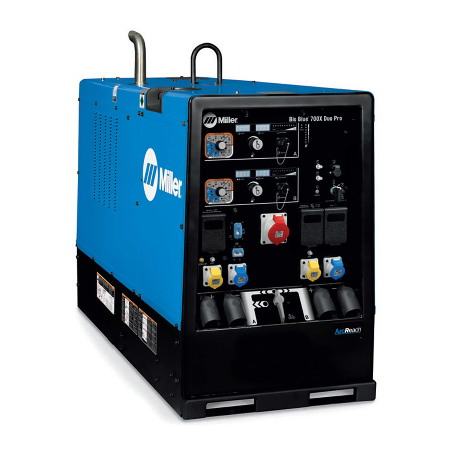
Big Blue 700X Duo Pro
OM-252 624D
Processes
Processes
Description
Engine Driven Welding Generator
)
)
2012−06
MIG (GMAW) Welding
Flux Cored (FCAW) Welding
Stick (SMAW) Welding
TIG (GTAW) Welding
Air Carbon Arc (CAC-A)
Cutting and Gouging
)
)
File: Engine Drive
Advertisement
Table of Contents
Troubleshooting

Subscribe to Our Youtube Channel
Related Manuals for Miller big blue 700x duo pro


Summary of Contents for Miller big blue 700x duo pro
- Page 1 Flux Cored (FCAW) Welding Stick (SMAW) Welding TIG (GTAW) Welding Air Carbon Arc (CAC-A) Cutting and Gouging Description Engine Driven Welding Generator Big Blue 700 Duo Pro Big Blue 700X Duo Pro File: Engine Drive Visit our website at www.MillerWelds.com...
- Page 2 We know you don’t have time to do it any other way. That’s why when Niels Miller first started building arc welders in 1929, he made sure his products offered long-lasting value and superior quality.
-
Page 3: Table Of Contents
TABLE OF CONTENTS SECTION 1 − SAFETY PRECAUTIONS − READ BEFORE USING ....... . 1-1. - Page 4 TABLE OF CONTENTS 6-4. Arc Control ............... . . 6-5.
-
Page 5: Section 1 − Safety Precautions − Read Before Using
SECTION 1 − SAFETY PRECAUTIONS − READ BEFORE USING rom_2011−10 Protect yourself and others from injury — read, follow, and save these important safety precautions and operating instructions. 1-1. Symbol Usage DANGER! − Indicates a hazardous situation which, if Indicates special instructions. not avoided, will result in death or serious injury. - Page 6 D Do not weld on containers that have held combustibles, or on FUMES AND GASES can be hazardous. closed containers such as tanks, drums, or pipes unless they are properly prepared according to AWS F4.1 and AWS A6.0 (see Welding produces fumes and gases. Breathing these Safety Standards).
-
Page 7: Engine Hazards
1-3. Engine Hazards EXHAUST SPARKS can cause fire. BATTERY EXPLOSION can injure. D Do not let engine exhaust sparks cause fire. D Always wear a face shield, rubber gloves, and protective clothing when working on a battery. D Use approved engine exhaust spark arrestor in required areas —... -
Page 8: Additional Symbols For Installation, Operation, And Maintenance
HOT METAL from air arc cutting and MOVING PARTS can injure. gouging can cause fire or explosion. D Keep away from moving parts such as fans, D Do not cut or gouge near flammables. belts and rotors. D Watch for fire; keep extinguisher nearby. D Keep all doors, panels, covers, and guards closed and securely in place. - Page 9 BATTERY CHARGING OUTPUT and BATTERY STATIC (ESD) can damage PC boards. EXPLOSION can injure. D Put on grounded wrist strap BEFORE handling Battery charging not present on all models. boards or parts. D Use proper static-proof bags and boxes to D Always wear a face shield, rubber gloves, and protective store, move, or ship PC boards.
-
Page 10: California Proposition 65 Warnings
1-6. California Proposition 65 Warnings For Gasoline Engines: Welding or cutting equipment produces fumes or gases which contain chemicals known to the State of California to Engine exhaust contains chemicals known to the State of cause birth defects and, in some cases, cancer. (California California to cause cancer, birth defects, or other reproduc- Health &... -
Page 11: Section 2 − Consignes De Sécurité − Lire Avant Utilisation
SECTION 2 CONSIGNES DE SÉCURITÉ − LIRE AVANT − UTILISATION fre_rom_2011−10 Pour écarter les risques de blessure pour vous−même et pour autrui — lire, appliquer et ranger en lieu sûr ces consignes relatives aux précautions de sécurité et au mode opératoire. 2-1. - Page 12 Il reste une TENSION DC NON NÉGLIGEABLE dans les LES RAYONS DE L’ARC peuvent sources de soudage onduleur UNE FOIS le moteur coupé. provoquer des brûlures dans les yeux et sur la peau. D Couper l’alimentation du poste et décharger les condensateurs d’entrée comme indiqué...
-
Page 13: Dangers Existant En Relation Avec Le Moteur
D Protéger les bouteilles de gaz comprimé d’une chaleur excessive, LE BRUIT peut affecter l’ouïe. des chocs mécaniques, des dommages physiques, du laitier, des flammes ouvertes, des étincelles et des arcs. Le bruit des processus et des équipements peut D Placer les bouteilles debout en les fixant dans un support station- affecter l’ouïe. -
Page 14: Dangers Liés À L'air Comprimé
LA VAPEUR ET LE LIQUIDE DE L’ACIDE DE LA BATTERIE peut pro- REFROIDISSEMENT CHAUD peuvent voquer des brûlures dans les YEUX et provoquer des brûlures. sur la PEAU. D Il est préférable de vérifier le liquide de refroi- D Ne pas renverser la batterie. dissement une fois le moteur refroidi pour éviter D Remplacer une batterie endommagée. -
Page 15: Dangers Supplémentaires En Relation Avec L'installation, Le Fonctionnement Et La Maintenance
détendre la pression et s’assurer que le circuit d’air ne peut être L’INHALATION D’AIR COMPRIMÉ risque mis sous pression par inadvertance. de provoquer des blessures ou même D Demander seulement à un personnel qualifié d’enlever la mort. les dispositifs de sécurité ou les recouvrements pour effectuer, s’il y a lieu, des travaux d’entretien et de dépannage. - Page 16 LA SORTIE DE RECHARGE et L’EXPLO- LES CHARGES ÉLECTROSTATI- SION BATTERIE peuvent QUES peuvent endommager les provoquer des blessures. circuits imprimés. D Établir la connexion avec la barrette de terre La recharge de batterie n’existe pas sur tous les avant de manipuler des cartes ou des pièces. modèles.
-
Page 17: Proposition Californienne 65 Avertissements
2-6. Proposition californienne 65 Avertissements Pour les moteurs à essence : Les équipements de soudage et de coupage produisent des fumées et des gaz qui contiennent des produits chimiques Les gaz d’échappement des moteurs contiennent des pro- dont l’État de Californie reconnaît qu’ils provoquent des mal- duits chimiques dont l’État de Californie reconnaît qu’ils formations congénitales et, dans certains cas, des cancers. -
Page 18: Section 3 − Definitions
SECTION 3 − DEFINITIONS 3-1. Additional Safety Symbols And Definitions Some symbols are found only on CE products. Warning! Watch Out! There are possible hazards as shown by the symbols. Safe1 2012−05 Wear dry insulating gloves. Do not touch electrode with bare hand. Do not wear wet or damaged gloves. Safe2 2012−05 Protect yourself from electric shock by insulating yourself from work and ground. - Page 19 Do not work on unit if engine is running. Stop engine first. Safe21 2012−05 Do not smoke while fueling or if near fuel. Safe22 2012−05 Stop engine before fueling. Safe23 2012−05 Do not fuel a hot engine. Safe24 2012−05 Use lift eye to lift unit and properly installed accessories only, not gas cylinders. Do not exceed maximum lift eye rating (see Specifications).
- Page 20 0 - 50 h std During the first 50 hours of operation keep welding load above 200 amperes. Do not weld below 200 amperes of output. Safe54 2012−05 50 h std After the first 50 hours of operation, change the engine oil and filter. Safe55 2012−05 Notes Work like a Pro!
-
Page 21: Miscellaneous Symbols And Definitions
3-2. Miscellaneous Symbols And Definitions Fast (Run, Weld/ Stop Engine Slow (Idle) Start Engine Power) Starting Aid Engine Oil Battery (Engine) Engine Oil (Preheat) Pressure Check Injectors/ Check Valve Protective Earth Fuel Pump Clearance (Ground) Certified/Trained Positive Negative Welding Arc Mechanic Amperes Volts... -
Page 22: Section 4 − Specifications
SECTION 4 − SPECIFICATIONS 4-1. Weld, Power, And Engine Specifications Weld Output Weld Weld Output Rated at Maximum Generator Power Sound Process Mode Output 1045F (405C) Open- Output Rated at Level at Range Circuit 1045F (405C) Rated Out- Voltage put, 23ft (7m) CC/DC Paralleled... -
Page 23: Dimensions, Weights, And Operating Angles
4-3. Dimensions, Weights, And Operating Angles Dimensions 60 in. (1524 mm) Height (to top of muffler) 28-1/2 in. (724 mm) (mtg. brackets turned in) Width 30-3/4 in. (781 mm) (mtg. brackets turned out) Depth 65-1/8 in. (1654 mm) Do not exceed tilt angles or engine could 65-1/8 in. -
Page 24: Volt-Ampere Curves
4-4. Volt-Ampere Curves The volt-ampere curves show the A. Stick Mode minimum and maximum voltage and amperage output capabilities of the welding generator. Curves of all other settings fall between the curves shown. DC AMPERES B. TIG Mode DC AMPERES C. -
Page 25: Volt-Ampere Curves For Paralleled Output
4-5. Volt-Ampere Curves For Paralleled Output The volt-ampere curves show the A. Stick Mode minimum and maximum voltage and amperage output capabilities of the welding generator. Curves of all other settings fall between the curves shown. PARALLELED OUTPUT DC AMPERES B. -
Page 26: Fuel Consumption
4-6. Fuel Consumption The curve shows typical fuel use under weld or power loads. 2.75 10.41 9.46 2.50 Paralleled Arc Dual Arcs 2.25 8.52 7.57 2.00 6.62 1.75 1.50 5.69 Single Arc 4.73 1.25 3.79 1.00 2.84 0.75 1.90 0.50 IDLE 0.25 0.00... -
Page 27: Ac Generator Power Curves
4-8. AC Generator Power Curves The AC power curve shows the generator power in amperes. A. Single Phase 4 kW 2 8 0 2 6 0 2 4 0 2 2 0 2 0 0 1 8 0 AC AMPERES B. - Page 28 4-7. AC Generator Power Curves (Continued) The AC power curve shows the generator power in amperes. C. Single Phase 12 kW AC AMPERES D. Three Phase North American 20 kW AC AMPERES 254 115-A / 254 114-A OM-252 624 Page 24...
-
Page 29: Section 5 − Installation
SECTION 5 − INSTALLATION 5-1. Serial Number And Rating Label Locations The serial number and rating information for this product is located on the front. Use rating label to determine input power requirements and/or rated output. For future reference, write serial number in space provided on back cover of this manual. 5-2. -
Page 30: Mounting Welding Generator
5-3. Mounting Welding Generator Do not weld on base. Weld- ing on base can cause fuel tank fire or explosion. Weld only on the four mounting brackets or bolt unit down. Supporting The Unit NOTICE − Do not mount unit by supporting the base only at the four mounting brackets. -
Page 31: Grounding Generator To Truck Or Trailer Frame
5-4. Grounding Generator To Truck Or Trailer Frame GND/PE rot_grnd2 2012−03 − 800 652-D frame. Always connect a ground Equipment Grounding Terminal (On Always ground generator frame to wire from the generator equipment Front Panel) vehicle frame to prevent electric grounding terminal to bare metal on shock and static electricity hazards. -
Page 32: Connecting The Battery
5-6. Connecting The Battery Connect negative (−) battery cable last. Close cover after connecting bat- tery. Tools Needed: 1/2 in. − Ref. 236 970 / 907 520−4 Notes WELD POSITION: FLAT HORIZONTAL VERTICAL OVERHEAD BUTT BUTT WELD JOINT BUTT BUTT TYPES T−JOINT T−JOINT... -
Page 33: Engine Prestart Checks
5-7. Engine Prestart Checks NOTICE − Follow run-in Full procedure in engine manual. If unburned fuel and oil collect in exhaust pipe, see Section 10. Diesel Full 907 520−4 Fuel Check all engine fluids daily. To improve cold weather starting: NOTICE −... -
Page 34: Connecting To Weld Output Terminals
5-8. Connecting To Weld Output Terminals Stop engine. Failure to properly connect weld cables may cause excessive heat and start a fire, or damage your ma- Tools Needed: chine. 3/4 in. Do not place anything between weld cable terminal and copper bar. Make sure that the surfaces of the weld cable terminal and copper bar are clean. -
Page 35: Making Dual Operator Cc Weld Connections W/ Separate Work Cables
5-9. Making Dual Operator CC Weld Connections w/ Separate Work Cables Tools Needed: 3/4 in. Optional Weld Selector switch shown. Direct Current Electrode Positive Welder A (Left) Side Welder B (Right) Side (DCEP) connections are shown. Ref. 251 340-A / Ref. 802 292-A Electrode Holder Cables For Stick/TIG Direct Current Electrode Stop engine. -
Page 36: Making Dual Operator Mode Cc Weld Connections W/ Common Work Cable
5-10. Making Dual Operator Mode CC Weld Connections w/ Common Work Cable Tools Needed: 3/4 in. Optional Weld Selector switch shown. Direct Current Electrode Positive Welder A (Left) Side (DCEP) connections are shown. Welder B (Right) Side Ref. 251 340-A / Ref. 802 292-A work cable must be able to carry combined other end of work jumper cable to Welder A Stop engine. -
Page 37: Making Dual Operator Cv Weld Connections W/ Separate Work Cables
5-11. Making Dual Operator CV Weld Connections w/ Separate Work Cables Tools Needed: 3/4 in. Optional Weld Selector switch shown. Direct Current Electrode Positive Welder A (Left) Side (DCEP) connections are shown. Welder B (Right) Side Ref. 251 340-A / Ref. 802 292-A Wire Feeder Cables For MIG and FCAW Direct Current Elec- Stop engine. -
Page 38: Making Dual Operator Cv Weld Connections W/ Common Work Cable
5-12. Making Dual Operator CV Weld Connections w/ Common Work Cable Tools Needed: 3/4 in. Optional Weld Selector switch shown. Direct Current Electrode Positive Welder A (Left) Side (DCEP) connections are shown. Welder B (Right) Side Ref. 251 340-A / Ref. 802 292-A weld output of both modules (see Section mon work cable and work jumper cable to Stop engine. -
Page 39: Making Dual Operator Cc And Cv Weld Connections W/ Separate Work Cables
5-13. Making Dual Operator CC And CV Weld Connections w/ Separate Work Cables Tools Needed: 3/4 in. Optional Weld Selector switch shown. Direct Current Electrode Positive (DCEP) connections are shown. Welder A (Left) Side Welder B (Right) Side Ref. 251 340-A / Ref. 802 292-A For Stick/TIG welding Direct Current Elec- For MIG and FCAW welding Direct Current Stop engine. -
Page 40: Making Dual Operator Cc And Cv Weld Connections W/ Common Work Cable
5-14. Making Dual Operator CC And CV Weld Connections w/ Common Work Cable Tools Needed: 3/4 in. Optional Weld Selector switch shown. Direct Current Electrode Positive Welder A (Left) Side (DCEP) connections are shown. Welder B (Right) Side Ref. 251 340-A / Ref. 802 292-A 5-16 for proper cable size). -
Page 41: Making Single Operator Cc Weld Connections
5-15. Making Single Operator CC Weld Connections Welder B (right) Terminals Optional Weld Selector switch shown. Inactive In Single Operator Mode Direct Current Electrode Positive Welder A (Left) Side (DCEP) connections are shown. Tools Needed: 3/4 in. Ref. 251 340-A / Ref. 802 292-A For Stick/TIG welding Direct Current Elec- Stop engine. -
Page 42: Weld Output Terminals And Selecting Cable Sizes
**Weld cable size (AWG) is based on either a 4 volts or less drop or a current density of at least 300 circular mils per ampere. ( ) = mm for metric use ***For distances longer than those shown in this guide, call a factory applications rep. at 920-735-4505 (Miller) or 1-800-332-3281 (Hobart). Ref. S-0007-J 2011−07 OM-252 624 Page 38... -
Page 43: Connecting To Remote 14 Receptacle
5-17. Connecting To Remote 14 Receptacle Socket* Socket Information Not all models have contactor control. See description of front panel controls and circuit diagram. 24 volts AC. Protected by supplementary protector. 24 VOLTS AC Contact closure to A completes 24 volt AC contactor control circuit. -
Page 44: Section 6 − Operating Welding Generator
SECTION 6 − OPERATING WELDING GENERATOR 6-1. Front Panel Controls (See Section 6-2) 251 246-A / 251 340-A OM-252 624 Page 40... -
Page 45: Description Of Front Panel Controls (See Section 6-1)
- 60 psi (207 - 414 kPa). perage control to the remote control (see Sec- NOTICE − Diesel engines in MILLER equip- NOTICE − Do not run engine until trouble is tion 6-6). ment are meant to operate optimally at rated fixed. -
Page 46: Process/Contactor Switch
6-3. Process/Contactor Switch Process/Contactor Switch Weld output terminals are ener- gized when Process/Contactor switch is in an Electrode Hot position and the engine is run- ning. Use switch to select weld process and weld output on/off control (see table be- low). -
Page 47: Arc Control
6-4. Arc Control Arc Control Stick Control adjusts Dig when Stick is se- lected on mode switch. When control is set toward minimum, short-circuit amperage at low arc voltage is the same as normal weld- ing amperage. When set toward maximum, short- circuit amperage is increased at low arc voltage to help prevent the elec- trode from sticking while welding (see... -
Page 48: Lift-Arct Tig With Auto-Stopt
6-5. Lift-Arct TIG With Auto-Stopt Arc Start With Lift-Arc TIG Lift-Arc is used for the DCEN GTAW process when HF Start method is not permitted. Arc Start With Lift-Arc Select Lift-Arc TIG at Process/ Contactor switch. Turn gas on. Touch or scratch. Lift at any angle. -
Page 49: Remote Voltage/Amperage Control
6-6. Remote Voltage/Amperage Control Remote 14 Receptacle Connect optional remote control to receptacle (see Section 5-17). When a remote control is connected to the Remote receptacle, the Auto Sense Re- mote feature automatically switches volt- age/amperage control to the remote con- trol. -
Page 50: Oil Pan Heater
6-7. Oil Pan Heater Oil Heater Plug Use heater to maintain a constant engine oil temperature. To turn on heater, connect heater plug to 120 volts AC receptacle. Heater rated at 300 watts. Do not run engine while oil pan heater is on. NOTICE −In extremely cold weath- er, heater should be connected to power source when engine oil is... -
Page 51: Fuel/Hour Gauge Descriptions
6-8. Fuel/Hour Gauge Descriptions OM-252 624 Page 47... -
Page 52: Section 7 − Operating Auxiliary Equipment
SECTION 7 − OPERATING AUXILIARY EQUIPMENT 7-1. North American Auxiliary Power Receptacles 251 249-A / 248 894-A Single-Phase Generator Power CB6 protects RC1 and RC2, and the gen- (240 V x 13 A) + (120 V x 7 A) = erator winding from overload. -
Page 53: Export Auxiliary Power Receptacles
7-2. Export Auxiliary Power Receptacles Ref. 251 252-A / 251 965-A 110 V 16 A AC Receptacle RC1 Supplementary Protector CB1 10 Supplementary Protector CB8 (Deluxe Model) 220 V 16 A AC Receptacle RC3 CB8 protects GFCI2 and RC2 from over- load. -
Page 54: Gfci Receptacle Information, Resetting And Testing
7-3. GFCI Receptacle Information, Resetting And Testing Test and reset GFCI only at Run speed. RotGFCI1 2012−05 If a ground fault is detected, the GFCI Reset Check for damaged or wet tools, cords, Use GFCI protection when operat- button pops out, and the circuit opens to plugs, etc. -
Page 55: Section 8 − Maintenance & Troubleshooting
SECTION 8 − MAINTENANCE & TROUBLESHOOTING 8-1. Maintenance Label DEUTZ DEUTZ Service: http://www.deutzamericas.com To ensure rapid, efficient service support, you should initially contact your nearest DEUTZ ser- vice distributor or dealer: http://www.deutzamer- icas.com/deutznew/distributors/index.htm. They are staffed with highly qualified parts, ser- vice and engine specialists to handle your differ- ent needs. -
Page 56: Routine Maintenance
8-2. Routine Maintenance Stop engine before maintaining. See Engine Manual and Maintenance Label Recycle engine for important start-up, service, and storage fluids. information. Service engine more often if used in severe conditions. n = Check Z = Change ~ = Clean l = Replace Reference * To be done by Factory Authorized Service Agent... -
Page 57: Checking Generator Brushes
8-3. Checking Generator Brushes Stop engine and let cool. Generator Brush Mark and disconnect leads at brush hold- er cap. Remove brushes. Minimum Length: Replace brushes if damaged or if brush 5/8 in. (16 mm) material is at or near minimum length. New Length: 1-1/4 in. -
Page 58: Servicing Air Cleaner
8-4. Servicing Air Cleaner Keep nozzle 2 in. (51 mm) from element. Optional Blow Inspect Unlatch dust cover, allow it to drop. Remove primary ele- ment. Dust cover can then be removed for cleaning. aircleaner1 2011−08− ST-153 929-B / ST-153 585 / Ref. S-0698-B stalling an optional safety element to Wipe off cover and housing. -
Page 59: Adjusting Engine Speed
8-5. Adjusting Engine Speed Stop engine and let cool. For operation at high altitude, engine may require adjust- ment. If adjustment is neces- sary, contact engine manufac- turer’s Factory Authorized Ser- vice Agent. Engine speed is factory set and 1860 rpm Max. should not require adjustment. -
Page 60: Servicing Fuel And Lubrication Systems
8-6. Servicing Fuel And Lubrication Systems Tools Needed: 907 520−4 in base. See engine manual and engine To replace secondary fuel filter: Stop engine and let cool. maintenance label for oil/filter change in- See engine manual. After servicing, start engine and formation. -
Page 61: Overload Protection
8-7. Overload Protection Stop engine. When a supplementary protector, cir- cuit breaker or fuse opens, it usually indicates a more serious problem ex- ists. Contact Factory Authorized Ser- vice Agent. Fuse F1 Fuse F2 F1 and F2 protect the stator exciter wind- ing from overload. -
Page 62: Voltmeter/Ammeter Help Displays
8-8. Voltmeter/Ammeter Help Displays HL.P HL.P HL.P HL.P HL.P Use the Voltmeter/Ammeter help displays side) on the heat sink has failed. If this dis- and then disconnected. Clear fault by stop- to diagnose and correct fault conditions. play is shown, have Factory Authorized ping and restarting the unit or by turning Service Agent check TH1 (each side), and Process/Contactor switch to another posi-... -
Page 63: Troubleshooting
8-9. Troubleshooting Also see Voltmeter/Ammeter help displays to assist in troubleshooting weld problems (see Section 8-8). A. Welding Trouble Remedy No weld output; generator power output Place Process/Contactor switch in an Electrode Hot position, or place switch in a Remote On/Off Re- okay at AC receptacles. - Page 64 Trouble Remedy Min or max CV weld output only. Check position of Voltage/Amperage Adjust control and Process/Contactor switch. Repair or replace remote control device. Have Factory Authorized Service Agent check Amperage/Voltage Adjust Control and field current regulator board. B. Standard Generator Power Trouble Remedy No generator power output at AC recept-...
- Page 65 D. Engine Trouble Remedy Engine will not crank. Supplementary protector CB2 open. Reset CB2. Check battery connections and tighten if necessary. Check battery, and replace if necessary. Circuit breaker CB10 may be open. CB10 automatically resets when fault is corrected (see Section 8-7). Have Factory Authorized Service Agent check engine wiring harness and components.
-
Page 66: Section 9 − Electrical Diagrams
SECTION 9 − ELECTRICAL DIAGRAMS Figure 9-1. Circuit Diagram For Export Welding Generator OM-252 624 Page 62... - Page 67 250 340-E OM-252 624 Page 63...
- Page 68 Figure 9-2. Circuit Diagram For North American Welding Generator OM-252 624 Page 64...
- Page 69 249 603-D OM-252 624 Page 65...
-
Page 70: Section 10 − Run-In Procedure
SECTION 10 − RUN-IN PROCEDURE Ref: run_in1 2007−04 Duo Pro 10-1. Wetstacking NOTICE − Do not perform run-in procedure at less than 20 volts weld output and do not exceed duty cycle or equipment damage may occur. Welding Generator Run diesel engines near rated volt- age and current during run-in period to properly seat piston rings and prevent wetstacking. -
Page 71: Run-In Procedure Using Load Bank
10-2. Run-In Procedure Using Load Bank Stop engine. Do not touch hot exhaust pipe, engine parts, or load bank/grid. Keep exhaust and pipe away from flammables. NOTICE − Do not perform run-in procedure at less than 20 volts weld output and do not exceed duty cycle or equipment damage may occur. -
Page 72: Run-In Procedure Using Resistance Grid
10-3. Run-In Procedure Using Resistance Grid Stop engine. Do not touch hot exhaust pipe, engine parts, or load bank/grid. Keep exhaust and pipe away from flammables. NOTICE − Do not perform run-in procedure at less than 20 volts weld output and do not exceed duty cycle or equipment damage may occur. -
Page 73: Section 11 − Generator Power Guidelines
SECTION 11 − GENERATOR POWER GUIDELINES The views in this section are intended to be representative of all engine-driven welding generators. Your unit may differ from those shown. 11-1. Selecting Equipment Generator Power Receptacles − Neutral Bonded To Frame 3-Prong Plug From Case Grounded Equipment 2-Prong Plug From Double Insulated Equipment... - Page 74 11-3. Grounding When Supplying Building Systems Equipment Grounding Terminal Grounding Cable Use #8 AWG or larger insulated copper wire. GND/PE Ground Device Use ground device as stated in electrical codes. Ground generator to system earth ground if supplying power to a premises (home, shop, farm) wiring system.
- Page 75 11-5. Approximate Power Requirements For Industrial Motors Industrial Motors Rating Starting Watts Running Watts Split Phase 1/8 HP 1/6 HP 1225 1/4 HP 1600 1/3 HP 2100 1/2 HP 3175 Capacitor Start-Induction Run 1/3 HP 2020 1/2 HP 3075 3/4 HP 4500 1400 1 HP...
- Page 76 11-7. Approximate Power Requirements For Contractor Equipment Contractor Rating Starting Watts Running Watts Hand Drill 1/4 in 3/8 in 1/2 in Circular Saw 6-1/2 in 7-1/4 in 8-1/4 in 1400 1400 Table Saw 9 in 4500 1500 10 in 6300 1800 Band Saw 14 in...
- Page 77 11-8. Power Required To Start Motor Single-Phase Induction Motor Starting Requirements Motor Start Code KVA/HP 10.0 11.2 12.5 14.0 Motor Start Code Running Amperage Motor HP Motor Voltage To find starting amperage: Step 1: Find code and use table to find kVA/HP.
- Page 78 11-10. Typical Connections To Supply Standby Power Have only qualified persons perform these connections according to all applicable codes and safety practices. Properly install, ground, and operate this equipment ac- cording to its Owner’s Manu- Fused Welding Utility al and national, state, and lo- Disconnect Electrical Generator...
- Page 79 11-11. Selecting Extension Cord (Use Shortest Cord Possible) Cord Lengths for 120 Volt Loads Use GFCI protection when operating auxiliary equipment. If unit does not have GFCI receptacles, use GFCI-protected exten- sion cord. Do not use GFCI receptacles to power life support equipment. Maximum Allowable Cord Length in ft (m) for Conductor Size (AWG)* Current Load (Watts)
-
Page 80: Section 12 − Parts List
SECTION 12 − PARTS LIST Hardware is common and not available unless listed. 907 520−5 Figure 12-1. Main Assembly − Part 1 OM-252 624 Page 76... - Page 81 Item Dia. Part Mkgs. Description Quantity Figure 12-1. Main Assembly − Part 1 ......Front Panel see Figure 12-4 thru Figure 12-8 .
- Page 82 66 67 907 520−7 Figure 12-2. Main Assembly − Part 2 OM-252 624 Page 78...
- Page 83 Item Dia. Part Mkgs. Description Quantity Figure 12-2. Main Assembly − Part 2 ....201934 Cover, Top ............
- Page 84 Item Dia. Part Mkgs. Description Quantity Figure 12-2. Main Assembly − Part 2 (Continued) ....252810 Channel, Stiffener Engine Access ........
- Page 85 Hardware is common and not available unless listed. 250 987-A Figure 12-3. Control Box Assembly Item Dia. Part Mkgs. Description Quantity Figure 12-3. Control Box Assembly (Figure 12-1 Item 21) ....046432 Holder, Fuse Mintr .250 X 1.250 .
- Page 86 Hardware is common and not available unless listed. 12 13 907 520−6A Figure 12-4. Panel, Front Engine & Weld Controls Item Dia. Part Mkgs. Description Quantity Figure 12-4. Panel, Front Engine & Weld Controls ....218764 Knob, Pointer 1.625 Dia .
- Page 87 Hardware is common and not available unless listed. 907 520−6B Figure 12-5. Panel, Weld Output Item Dia. Part Mkgs. Description Quantity Figure 12-5. Panel, Weld Output ....186621 Boot, Generic Output Stud .
- Page 88 907 520−6C Figure 12-6. Panel, Auxiliary Power North America Item Dia. Part Mkgs. Description Quantity Figure 12-6. Panel, Auxiliary Power North America ....214927 Boot,Circuit Breaker 1 Pole .
- Page 89 907 520−6D Figure 12-7. Panel, Auxiliary Power Export Item Dia. Part Mkgs. Description Quantity Figure 12-7. Panel, Auxiliary Power Export ....209056 Cover, Receptacle W/Gasket .
- Page 90 907 520−6E Figure 12-8. Panel, Auxiliary Power Export Deluxe Item Dia. Part Mkgs. Description Quantity Figure 12-8. Panel, Auxiliary Power Export Deluxe ....209056 Cover, Receptacle W/Gasket .
- Page 91 907 520−9 Figure 12-9. Weld Control Assembly Item Dia. Part Mkgs. Description Quantity Figure 12-9. Weld Control Assembly (Figure 12-1 Item 11) ....250348 Bus Bar, Negative .
- Page 92 Hardware is common and not available unless listed. 802 404-C Figure 12-10. Generator Item Dia. Part Mkgs. Description Quantity Figure 12-10. Generator (Figure 12-2 Item 27) ....132053 Screw, 375-16 X 1.50hexhd Pln Gr 5pld .
- Page 93 Item Dia. Part Mkgs. Description Quantity Figure 12-10. Generator (Continued) ....049026 Screw, M10−1.5x 25 Hex Hd−Pln 8.8 Pln ......
- Page 94 Some wiring harness components (switches, relays, supplementary protectors) are also referenced elsewhere in this parts list. Purchase compo- nents separately or as part of the associated wiring harness. Item Dia. Part Mkgs. Description Quantity Wiring Harnesses ....251608 Harness, Engine 2011 NA (Includes) .
- Page 95 Effective January 1, 2012 (Equipment with a serial number preface of MC or newer) This limited warranty supersedes all previous Miller warranties and is exclusive with no other Warranty Questions? guarantees or warranties expressed or implied. LIMITED WARRANTY − Subject to the terms and conditions 90 Days —...
- Page 96 Contact the Delivering Carrier to: File a claim for loss or damage during shipment. For assistance in filing or settling claims, contact your distributor and/or equipment manufacturer’s Transportation Department. © ORIGINAL INSTRUCTIONS − PRINTED IN USA 2012 Miller Electric Mfg. Co. 2012−01...
Need help?
Do you have a question about the big blue 700x duo pro and is the answer not in the manual?
Questions and answers