Miller Bobcat 225 Owner's Manual
Hide thumbs
Also See for Bobcat 225:
- Application manual (16 pages) ,
- Owner's manual (80 pages) ,
- Owner's manual (80 pages)
Table of Contents
Troubleshooting

Related Manuals for Miller Bobcat 225


Summary of Contents for Miller Bobcat 225
- Page 1 OM-4434 218 653P 2010−04 Processes Stick (SMAW) Welding MIG (GMAW) Welding Flux Cored (FCAW) Welding Non-Critical TIG (GTAW) Welding Description Engine Driven Welding Generator Bobcat 225 ™ File: Engine Drive Visit our website at www.MillerWelds.com...
- Page 2 We know you don’t have time to do it any other way. That’s why when Niels Miller first started building arc welders in 1929, he made sure his products offered long-lasting value and superior quality.
-
Page 3: Table Of Contents
TABLE OF CONTENTS SECTION 1 − SAFETY PRECAUTIONS − READ BEFORE USING ....... . 1-1. - Page 4 TABLE OF CONTENTS SECTION 8 − MAINTENANCE ............. . . 8-1.
-
Page 5: Section 1 − Safety Precautions − Read Before Using
SECTION 1 − SAFETY PRECAUTIONS − READ BEFORE USING rom_2010−03 Protect yourself and others from injury — read, follow, and save these important safety precautions and operating instructions. 1-1. Symbol Usage DANGER! − Indicates a hazardous situation which, if Indicates special instructions. not avoided, will result in death or serious injury. - Page 6 D Do not weld on closed containers such as tanks, drums, or pipes, FUMES AND GASES can be hazardous. unless they are properly prepared according to AWS F4.1 (see Safety Standards). Welding produces fumes and gases. Breathing these D Do not weld where the atmosphere may contain flammable dust, fumes and gases can be hazardous to your health.
-
Page 7: Engine Hazards
1-3. Engine Hazards EXHAUST SPARKS can cause fire. BATTERY EXPLOSION can injure. D Do not let engine exhaust sparks cause fire. D Always wear a face shield, rubber gloves, and protective clothing when working on a battery. D Use approved engine exhaust spark arrestor in required areas —... -
Page 8: Hydraulic Hazards
1-4. Hydraulic Hazards D HYDRAULIC FLUID is FLAMMABLE−−do not work on hydraulics HYDRAULIC EQUIPMENT can injure near sparks or flames; do not smoke near hydraulic fluid. or kill. D Reinstall doors, panels, covers, or guards when servicing is D Incorrect installation or operation of this unit finished and before starting unit. -
Page 9: Additional Symbols For Installation, Operation, And Maintenance
HOT METAL from air arc cutting and MOVING PARTS can injure. gouging can cause fire or explosion. D Keep away from moving parts such as fans, D Do not cut or gouge near flammables. belts and rotors. D Watch for fire; keep extinguisher nearby. D Keep all doors, panels, covers, and guards closed and securely in place. -
Page 10: California Proposition 65 Warnings
WELDING WIRE can injure. H.F. RADIATION can cause interference. D Do not press gun trigger until instructed to do D High-frequency (H.F.) can interfere with radio navigation, safety services, computers, and communications equipment. D Do not point gun toward any part of the body, other people, or any metal when threading D Have only qualified persons familiar with welding wire. -
Page 11: Principal Safety Standards
1-8. Principal Safety Standards Safety in Welding, Cutting, and Allied Processes, ANSI Standard Z49.1, 25 West 43rd Street, New York, NY 10036 (phone: 212-642-4900, web- from Global Engineering Documents (phone: 1-877-413-5184, website: site: www.ansi.org). www.global.ihs.com). Standard for Fire Prevention During Welding, Cutting, and Other Hot Safe Practices for the Preparation of Containers and Piping for Welding Work, NFPA Standard 51B, from National Fire Protection Association, and Cutting, American Welding Society Standard AWS F4.1, from Glob-... -
Page 12: Section 2 − Consignes De Sécurité − Lire Avant Utilisation
SECTION 2 CONSIGNES DE SÉCURITÉ − LIRE AVANT − UTILISATION fre_rom_2010−03 Pour écarter les risques de blessure pour vous−même et pour autrui — lire, appliquer et ranger en lieu sûr ces consignes relatives aux précautions de sécurité et au mode opératoire. 2-1. - Page 13 D Porter un casque de soudage approuvé muni de verres filtrants LES PIÈCES CHAUDES peuvent approprié pour protéger visage et yeux pour protéger votre visage provoquer des brûlures. et vos yeux pendant le soudage ou pour regarder (voir ANSI Z49.1 et Z87.1 énuméré...
-
Page 14: Dangers Existant En Relation Avec Le Moteur
D Placer les bouteilles debout en les fixant dans un support station- Les CHAMPS ÉLECTROMAGNÉTIQUES (CEM) naire ou dans un porte-bouteilles pour les empêcher de tomber ou peuvent affecter les implants médicaux. de se renverser. D Tenir les bouteilles éloignées des circuits de soudage ou autres D Les porteurs de stimulateurs cardiaques et circuits électriques. -
Page 15: Dangers Liés À L'hydraulique
D Mettre des lunettes de sécurité et des gants, placer un torchon sur LES ÉTINCELLES À L’ÉCHAPPEMENT le bouchon du radiateur. peuvent provoquer un incendie. D Dévisser le bouchon légèrement et laisser la vapeur s’échapper avant d’enlever le bouchon. D Empêcher les étincelles d’échappement du moteur de provoquer un incendie. -
Page 16: Dangers Liés À L'air Comprimé
un médecin familiarisé avec ce type de blessure, faute de quoi LES PIÈCES ET LIQUIDES CHAUDS la gangrène pourrait apparaître. peuvent provoquer des brûlures. Les PIÈCES MOBILES peuvent causer D Ne pas toucher les pièces chaudes à main nue des blessures. ni laisser des liquides chauds entrer en contact avec la peau. -
Page 17: Dangers Supplémentaires En Relation Avec L'installation, Le Fonctionnement Et La Maintenance
D Remettre en place les portes, panneaux, recouvrements ou PRESSION D’AIR RÉSIDUELLE dispositifs de protection à la fin des travaux d’entretien et avant ET DES FLEXIBLES QUI FOUETTENT de mettre le moteur en marche. risquent de provoquer des blessures. D Détendre la pression pneumatique des outils et PIÈCES CHAUDES peuvent... -
Page 18: Proposition Californienne 65 Avertissements
D Demander seulement à des personnes qualifiées familiarisées LES CHARGES ÉLECTROSTATI- avec des équipements électroniques de faire fonctionner l’installa- QUES peuvent endommager les tion. circuits imprimés. D L’utilisateur est tenu de faire corriger rapidement par un électricien qualifié les interférences résultant de l’installation. D Établir la connexion avec la barrette de terre avant de manipuler des cartes ou des pièces. -
Page 19: Principales Normes De Sécurité
2-8. Principales normes de sécurité Safety in Welding, Cutting, and Allied Processes, ANSI Standard Z49.1, 25 West 43rd Street, New York, NY 10036 (phone: 212-642-4900, web- from Global Engineering Documents (phone: 1-877-413-5184, website: site: www.ansi.org). www.global.ihs.com). Standard for Fire Prevention During Welding, Cutting, and Other Hot Safe Practices for the Preparation of Containers and Piping for Welding Work, NFPA Standard 51B, from National Fire Protection Association, and Cutting, American Welding Society Standard AWS F4.1, from Glob-... -
Page 20: Section 3 − Definitions
A complete Parts List is available at www.MillerWelds.com SECTION 3 − DEFINITIONS 3-1. Symbol Definitions Fast Fast/Slow Stop Engine Slow (Idle) (Run, Weld/Power) (Run/Idle) Read Operator’s Start Engine Amperes Volts Manual Engine Oil Fuel Battery (Engine) Engine Check Valve Do not switch while Engine Choke Work Connection Clearance... -
Page 21: Dimensions, Weights, And Operating Angles
A complete Parts List is available at www.MillerWelds.com 4-2. Dimensions, Weights, And Operating Angles Do not exceed tilt angles or engine could be damaged or unit could tip. Do not move or operate unit ° where it could tip. Weight: 562 lb (254 kg) °... -
Page 22: Dimensions For Units With Optional Running Gear
A complete Parts List is available at www.MillerWelds.com 4-3. Dimensions For Units With Optional Running Gear Dimensions All Running Gear Options: 42-1/2 in (1079 mm) Height (To Top Of Handle Assembly) Protective Cage Width: 26 in (660 mm) Running Gear Width: 32 in (813 mm) Protective Cage Length: 48 in (1219 mm) -
Page 23: Fuel Consumption (Subaru-Powered Units)
A complete Parts List is available at www.MillerWelds.com 4-5. Fuel Consumption (Subaru-Powered Units) On a typical job using 1/8 in 7018 electrodes (125 amps, 20% duty cycle), expect about 20 hours of op- eration. Welding at 150 amps at 40% duty cycle uses approximately 3/4 gal- lon per hour, or about 16 hours of operation. -
Page 24: Volt-Ampere Curves
A complete Parts List is available at www.MillerWelds.com 4-7. Volt-Ampere Curves The volt-ampere curve shows the A. For CC/AC Mode minimum and maximum voltage and amperage output capabilities of the welding generator. Curves of all other settings fall between the curves shown. -
Page 25: Generator Power Curve
A complete Parts List is available at www.MillerWelds.com 4-8. Generator Power Curve The generator power curve shows the generator power in amperes available at the receptacles. 200 294 Notes WELD POSITION: FLAT HORIZONTAL VERTICAL OVERHEAD BUTT BUTT WELD JOINT BUTT BUTT TYPES T−JOINT... -
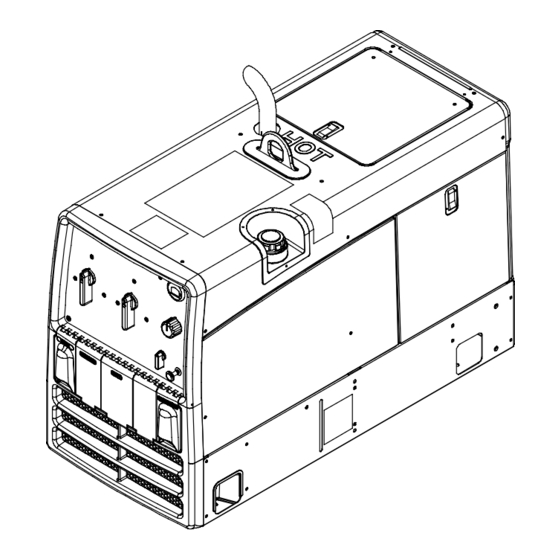
Page 26: Section 5 − Installation
A complete Parts List is available at www.MillerWelds.com SECTION 5 − INSTALLATION 5-1. Serial Number And Rating Label Location The serial number and rating information for this product is located on the back. Use rating label to determine input power requirements and/or rated output. -
Page 27: Grounding Generator To Truck Or Trailer Frame
A complete Parts List is available at www.MillerWelds.com 5-3. Grounding Generator To Truck Or Trailer Frame Always ground generator frame to vehicle frame to pre- vent electric shock and static electricity hazards. Also see AWS Safety & Health Fact Sheet No. 29, Grounding of Portable And Vehicle Mounted Welding Generators. -
Page 28: Engine Prestart Checks (Subaru-Powered Units)
A complete Parts List is available at www.MillerWelds.com 5-4. Engine Prestart Checks (Subaru-Powered Units) Check all fluids daily. Engine must be cold and on a level surface. Unit is shipped with 10W30 engine oil. Follow run-in procedure in en- gine manual. NOTICE −... -
Page 29: Engine Prestart Checks (Kohler-Powered Units)
A complete Parts List is available at www.MillerWelds.com 5-5. Engine Prestart Checks (Kohler-Powered Units) Check all fluids daily. Engine must be cold and on a level surface. Unit is shipped with 10W30 engine oil. Follow run-in procedure in en- gine manual. NOTICE −... -
Page 30: Installing Exhaust Pipe
A complete Parts List is available at www.MillerWelds.com 5-6. Installing Exhaust Pipe Engine backfire can cause se- vere burns or other injuries. Do not point exhaust pipe toward control panel. Keep away from exhaust outlet. Point exhaust pipe in desired di- rection but always away from front panel and direction of trav- Be sure to tighten exhaust clamp... -
Page 31: Weld Output Terminals
A complete Parts List is available at www.MillerWelds.com 5-8. Weld Output Terminals Stop engine. Failure to properly connect weld cables may cause exces- sive heat and start a fire, or damage your machine. Work Weld Output Terminal Electrode Weld Output Terminal Connect work cable to Work terminal. -
Page 32: Selecting Weld Cable Sizes
**Weld cable size (AWG) is based on either a 4 volts or less drop or a current density of at least 300 circular mils per ampere. ( ) = mm for metric use ***For distances longer than those shown in this guide, call a factory applications rep. at 920-735-4505 (Miller) or 1-800-332-3281 (Hobart) Ref. S-0007-G 2009−08 Notes... - Page 33 A complete Parts List is available at www.MillerWelds.com Notes Start Your Professional Over 80,000 400 Trade Square East, Troy, Ohio 45373 Welding Career Now! trained since 1930! 1-800-332-9448 www.welding.org OM-4434 Page 29...
-
Page 34: Section 6 − Operating The Welding Generator
A complete Parts List is available at www.MillerWelds.com SECTION 6 − OPERATING THE WELDING GENERATOR 6-1. Front Panel Controls Ref. 240 947-A Engine Control Switch Oil Change Interval: With engine off, place En- NOTICE − Do not switch under load. gine Control switch in the Run position to see Use switch to start engine, select speed, and Use switch to select weld amperage range... -
Page 35: Cold Weather Engine Operation
A complete Parts List is available at www.MillerWelds.com 6-2. Cold Weather Engine Operation Engine Control Switch Carburetor Icing Carburetor icing causes the unit to drop below the normal idle speed and then stall. This condition occurs when the temperature is near freezing and the rela- Infrequently tive humidity is high. -
Page 36: Typical Stick Welding Connections And Control Settings
A complete Parts List is available at www.MillerWelds.com 6-3. Typical Stick Welding Connections And Control Settings Stop engine. This section provides general guidelines and may not suit all applications. For best arc starts and best The control panel shows the typi- results using weld and generator cal settings for welding with a power together, use a low... -
Page 37: Typical Mig Welding Connections And Settings
A complete Parts List is available at www.MillerWelds.com 6-4. Typical MIG Welding Connections And Settings A. Solid Wire Applications Stop engine. This section provides general guide- lines and may not suit all ap- plications. Typical Control Settings For .035 (ER70S-3) The control panel shows the typical Solid Wire −... - Page 38 A complete Parts List is available at www.MillerWelds.com B. Self-Shielded Flux Core Wire Applications Stop engine. This section provides general guidelines and may not suit all applications. Typical Control Settings For .045 (71T-11) Self-Shielded Flux Core Wire The control panel shows the typi- cal settings for welding with .045 (71T-11) self-shielded flux core Note Coarse Range,...
-
Page 39: Typical Mig Connections And Settings Using Weld Control And Spoolgun
A complete Parts List is available at www.MillerWelds.com 6-5. Typical MIG Connections And Settings Using Weld Control And Spoolgun Typical Settings For 4043 (.035) Aluminum On 1/8 in. Material: Note Coarse Range and Weld Tools Needed: Process switch settings. 3/4 in. Connect to unused Work contactor terminal. -
Page 40: Section 7 − Operating Auxiliary Equipment
A complete Parts List is available at www.MillerWelds.com SECTION 7 − OPERATING AUXILIARY EQUIPMENT 7-1. Standard Receptacles If unit does not have GFCI re- ceptacles, use GFCI-protected extension cord. Generator power decreases as weld current increases. Set Fine Control R1 at 10 for full generator power. -
Page 41: Optional Generator Power Receptacles
A complete Parts List is available at www.MillerWelds.com 7-2. Optional Generator Power Receptacles If unit does not have GFCI recep- tacles, use GFCI-protected exten- sion cord. Generator power decreases as weld current increases. Set Fine Control R1 at 10 for full genera- tor power. -
Page 42: Simultaneous Weld And Power
A complete Parts List is available at www.MillerWelds.com 7-3. Simultaneous Weld And Power Weld Current in Amperes Total Power in Watts 120 V Full kVA Receptacle 240 V Full kVA Receptacle Amperes Amperes 2200 3500 5200 8000 11,000 7-4. Wiring Optional 240 Volt Plug The plug can be wired for a 240 V, 2-wire load or a 120/240V, 3-wire load. -
Page 43: Section 8 − Maintenance
A complete Parts List is available at www.MillerWelds.com SECTION 8 − MAINTENANCE 8-1. Maintenance Label OM-4434 Page 39... -
Page 44: Routine Maintenance
A complete Parts List is available at www.MillerWelds.com 8-2. Routine Maintenance Stop engine before maintaining. See Engine Manual and Maintenance Label Recycle engine for important start-up, service, and storage fluids. information. Service engine more often if used in severe conditions. n = Check Z = Change ~ = Clean... -
Page 45: Servicing Optional Spark Arrestor
A complete Parts List is available at www.MillerWelds.com 8-3. Servicing Optional Spark Arrestor Stop engine and let cool. Spark Arrestor Screen Clean and inspect screen. Replace spark arrestor if screen wires are broken or missing. Tools Needed: 1/4 in. Ref. 803 572−A / Ref. 183 175−A 8-4. -
Page 46: Overload Protection
A complete Parts List is available at www.MillerWelds.com 8-5. Overload Protection Stop engine. Disconnect negative (−) battery cable. Fuse F1 (See Section 10-1) Fuse F6 located in F1 protects the weld excitation harness behind left winding from overload. If F1 opens, side door. -
Page 47: Changing Engine Oil, Oil Filter, And Fuel Filter (Subaru-Powered Units)
A complete Parts List is available at www.MillerWelds.com 8-6. Changing Engine Oil, Oil Filter, and Fuel Filter (Subaru-Powered Units) Stop engine and let cool. Oil Drain Valve Oil Filter Change engine oil and filter accord- ing to engine owner’s manual. NOTICE −... -
Page 48: Changing Engine Oil, Oil Filter, And Fuel Filter (Kohler-Powered Units)
A complete Parts List is available at www.MillerWelds.com 8-7. Changing Engine Oil, Oil Filter, and Fuel Filter (Kohler-Powered Units) Stop engine and let cool. Oil Drain Valve 1/2 ID x 7 in Hose Oil Filter Change engine oil and filter accord- ing to engine owner’s manual. -
Page 49: Adjusting Engine Speed (Subaru-Powered Units)
A complete Parts List is available at www.MillerWelds.com 8-8. Adjusting Engine Speed (Subaru-Powered Units) After tuning engine, check engine speeds with a tachometer (see table). If necessary, adjust speeds as follows: Start engine and run until warm. Remove rear panel and air cleaner to access idle speed adjustments. -
Page 50: Adjusting Engine Speed (Kohler-Powered Units)
A complete Parts List is available at www.MillerWelds.com 8-9. Adjusting Engine Speed (Kohler-Powered Units) After tuning engine, check engine speeds with a tachometer (see table). If necessary, adjust speeds as follows: 2200 − 2300 rpm Start engine and run until warm. (36.6 −... -
Page 51: Section 9 − Troubleshooting
A complete Parts List is available at www.MillerWelds.com SECTION 9 − TROUBLESHOOTING 9-1. Welding Troubleshooting Trouble Remedy Low or no weld output; generator pow- Check control settings. er output okay at ac receptacles. Check weld connections. Check fuse F1, and replace if open (see Section 8-5). Have Factory Authorized Service Agent check brushes, slip rings, capacitor C1, and integrated rectifi- ers SR2 and SR3. -
Page 52: Engine Troubleshooting
A complete Parts List is available at www.MillerWelds.com Trouble Remedy No generator power or weld output. Be sure all equipment is disconnected from receptacles when starting unit. Check fuses F1 and F2, and replace if open (see Section 8-5). Check plug PLG6 connection. Have Factory Authorized Service Agent check brushes, slip rings, capacitor C1, and integrated rectifi- ers SR2 and SR3. -
Page 53: Section 10 − Parts List
A complete Parts List is available at www.MillerWelds.com Trouble Remedy Battery Discharges between uses. Clean battery, terminals, and posts with baking soda and water solution; rinse with clear water. Periodically recharge battery (approximately every 3 months). Replace battery. Check voltage regulator and connections according to engine manual. Engine idles but does not come up to Have Factory Authorized Service Agent check hour meter/idle module, and current transformer CT1. -
Page 54: Section 11 − Electrical Diagrams
SECTION 11 − ELECTRICAL DIAGRAMS Figure 11-1. Circuit Diagram For Welding Generator OM-4434 Page 50... - Page 55 239 805-B OM-4434 Page 51...
-
Page 56: Section 12 − Generator Power Guidelines
SECTION 12 − GENERATOR POWER GUIDELINES The views in this section are intended to be representative of all engine-driven welding generators. Your unit may differ from those shown. 12-1. Selecting Equipment Generator Power Receptacles − Neutral Bonded To Frame 3-Prong Plug From Case Grounded Equipment 2-Prong Plug From Double Insulated Equipment... -
Page 57: Grounding When Supplying Building Systems
12-3. Grounding When Supplying Building Systems Equipment Grounding Terminal Grounding Cable Use #10 AWG or larger insulated copper wire. Ground Device GND/PE Use ground device as stated in electrical codes. Ground generator to system earth ground if supplying power to a premises (home, shop, farm) wiring system. - Page 58 12-5. Approximate Power Requirements For Industrial Motors Industrial Motors Rating Starting Watts Running Watts Split Phase 1/8 HP 1/6 HP 1225 1/4 HP 1600 1/3 HP 2100 1/2 HP 3175 Capacitor Start-Induction Run 1/3 HP 2020 1/2 HP 3075 3/4 HP 4500 1400 1 HP...
- Page 59 12-7. Approximate Power Requirements For Contractor Equipment Contractor Rating Starting Watts Running Watts Hand Drill 1/4 in 3/8 in 1/2 in Circular Saw 6-1/2 in 7-1/4 in 8-1/4 in 1400 1400 Table Saw 9 in 4500 1500 10 in 6300 1800 Band Saw 14 in...
- Page 60 12-8. Power Required To Start Motor Single-Phase Induction Motor Starting Requirements Motor Start Code KVA/HP 10.0 11.2 12.5 14.0 Motor Start Code Running Amperage Motor HP Motor Voltage To find starting amperage: Step 1: Find code and use table to find kVA/HP.
- Page 61 12-10. Typical Connections To Supply Standby Power Have only qualified persons perform these connections according to all applicable codes and safety practices. Properly install and ground this equipment according to its Owner’s Manual and na- Fused tional, state, and local codes. Welding Utility Disconnect...
- Page 62 12-11. Selecting Extension Cord (Use Shortest Cord Possible) Cord Lengths for 120 Volt Loads If unit does not have GFCI receptacles, use GFCI-protected extension cord. Maximum Allowable Cord Length in ft (m) for Conductor Size (AWG)* Current Load (Watts) (Amperes) 350 (106) 225 (68) 137 (42)
-
Page 63: Section 13 − Stick Welding (Smaw) Guidelines
SECTION 13 − STICK WELDING (SMAW) GUIDELINES 13-1. Stick Welding Procedure Weld current starts when electrode touches work- piece. Equipment Needed: Tools Needed: Weld current can damage electronic parts in vehicles. Disconnect both battery cables before welding on a vehicle. Place work clamp as close to the weld as possible. -
Page 64: Electrode And Amperage Selection Chart
13-2. Electrode and Amperage Selection Chart 6010 DEEP 3/32 MIN. PREP, ROUGH HIGH SPATTER 6011 DEEP 6010 5/32 & 6013 EP,EN GENERAL 3/16 6011 7/32 SMOOTH, EASY, 7014 EP,EN FAST 1/16 LOW HYDROGEN, 7018 5/64 STRONG 3/32 FLAT SMOOTH, EASY, 7024 EP,EN HORIZ... -
Page 65: Positioning Electrode Holder
13-4. Positioning Electrode Holder End View Of Work Angle Side View Of Electrode Angle ° ° ° ° Groove Welds ° ° ° ° Fillet Welds S-0060 13-5. Poor Weld Bead Characteristics Large Spatter Deposits Rough, Uneven Bead Slight Crater During Welding Bad Overlap Poor Penetration S-0053-A... -
Page 66: Conditions That Affect Weld Bead Shape
13-7. Conditions That Affect Weld Bead Shape Weld bead shape is affected electrode angle, length, travel speed, and thick- ness of base metal. Correct Angle Angle Too Large ° - ° Angle Too Small Electrode Angle Drag Spatter Arc Length Normal Too Long Too Short... -
Page 67: Lap Joint
13-9. Groove (Butt) Joints Tack Welds Prevent edges of joint from draw- ing together ahead of electrode by tack welding the materials in posi- tion before final weld. Square Groove Weld Good for materials up to 3/16 in. (5 mm) thick. Single V-Groove Weld Good for materials 3/16 −... -
Page 68: Weld Test
13-12. Weld Test Vise Weld Joint Hammer Strike weld joint in direction shown. A good weld bends over but does not break. 2 To 3 in. (51-76 mm) 2 To 3 in. (51-76 mm) 1/4 in. (6.4 mm) S-0057-B 13-13. Troubleshooting Porosity −... - Page 69 Lack Of Penetration − shallow fusion between weld metal and base metal. Lack of Penetration Good Penetration Possible Causes Corrective Actions Improper joint preparation. Material too thick. Joint preparation and design must provide access to bottom of groove. Improper weld technique. Keep arc on leading edge of weld puddle.
-
Page 70: Section 14 − Mig Welding (Gmaw) Guidelines
SECTION 14 − MIG WELDING (GMAW) GUIDELINES mig spec 2009−12 14-1. Typical MIG Process Connections Using A Voltage-Sensing Wire Feeder Weld current can damage electronic parts in vehicles. Disconnect both battery cables before welding on a vehicle. Place work clamp as Constant close to the weld as possible. - Page 71 14-3. Conditions That Affect Weld Bead Shape Weld bead shape depends on gun angle, direction of travel, electrode extension (stickout), travel speed, thickness of base metal, wire feed speed (weld current), and voltage. ° Push ° Perpendicular Drag GUN ANGLES AND WELD BEAD PROFILES Short Normal Long...
-
Page 72: Gun Movement During Welding
14-4. Gun Movement During Welding Normally, a single stringer bead is satisfactory for most narrow groove weld joints; however, for wide groove weld joints or bridging across gaps, a weave bead or multiple stringer beads works better. Stringer Bead − Steady Movement Along Seam Weave Bead −... -
Page 73: Troubleshooting − Excessive Penetration
14-7. Troubleshooting − Excessive Spatter Excessive Spatter − scattering of molten metal particles that cool to solid form near weld bead. S-0636 Possible Causes Corrective Actions Wire feed speed too high. Select lower wire feed speed. Voltage too high. Select lower voltage range. Electrode extension (stickout) too long. -
Page 74: Troubleshooting − Lack Of Penetration
14-10. Troubleshooting − Lack Of Penetration Lack Of Penetration − shallow fusion between weld metal and base metal. Lack of Penetration Good Penetration S-0638 Possible Causes Corrective Actions Improper joint preparation. Material too thick. Joint preparation and design must provide access to bottom of groove while maintaining proper welding wire extension and arc characteristics. -
Page 75: Troubleshooting − Waviness Of Bead
14-13. Troubleshooting − Waviness Of Bead Waviness Of Bead − weld metal that is not parallel and does not cover joint formed by base metal. S-0641 Possible Causes Corrective Actions Welding wire extends too far out of nozzle. Be sure welding wire extends not more than 1/2 in (13 mm) beyond nozzle. Unsteady hand. -
Page 76: Common Mig Shielding Gases
14-15. Common MIG Shielding Gases This is a general chart for common gases and where they are used. Many different combinations (mixtures) of shielding gases have been developed over the years. The most commonly used shielding gases are listed in the following table. - Page 77 Effective January 1, 2010 (Equipment with a serial number preface of MA or newer) This limited warranty supersedes all previous Miller warranties and is exclusive with no other Warranty Questions? guarantees or warranties expressed or implied. LIMITED WARRANTY − Subject to the terms and conditions 90 Days —...
- Page 78 Contact the Delivering Carrier to: File a claim for loss or damage during shipment. For assistance in filing or settling claims, contact your distributor and/or equipment manufacturer’s Transportation Department. © ORIGINAL INSTRUCTIONS − PRINTED IN USA 2010 Miller Electric Mfg. Co. 2010−01...
Need help?
Do you have a question about the Bobcat 225 and is the answer not in the manual?
Questions and answers