Miller Bobcat 225 Owner's Manual
Hide thumbs
Also See for Bobcat 225:
- Owner's manual (78 pages) ,
- Application manual (16 pages) ,
- Owner's manual (80 pages)
Table of Contents
Advertisement
Advertisement
Table of Contents
Troubleshooting

Related Manuals for Miller Bobcat 225


Summary of Contents for Miller Bobcat 225
- Page 1 OM-286503C 2020-02 Processes Stick (SMAW) Welding MIG (GMAW) Welding Flux Cored (FCAW) Welding TIG (GTAW) Welding Description Engine Driven Welder/Generator Bobcat ™ OWNER’S MANUAL For product information, Owner’s Manual translations, and more, visit www.MillerWelds.com...
- Page 2 We know you don’t have time to do it any other way. That’s why when Niels Miller first started building arc welders in 1929, he made sure his products offered long-lasting value and superior quality.
-
Page 3: Table Of Contents
TABLE OF CONTENTS SECTION 1 – SAFETY PRECAUTIONS – READ BEFORE USING..............1 Symbol Usage . - Page 4 TABLE OF CONTENTS Recommended Spare Parts ..................49 SECTION 10 –...
-
Page 5: Section 1 - Safety Precautions - Read Before Using
SECTION 1 – SAFETY PRECAUTIONS – READ BEFORE USING Protect yourself and others from injury—read, follow, and save these important safety precautions and operating instructions. 1-1. Symbol Usage DANGER! – Indicates a hazardous situation which, if not � Indicates special instructions. avoided, will result in death or serious injury. - Page 6 � Mantenha sempre todos os painéis e tampas do Equipamento fir- � Não solde metais revestidos tais como chapas galvanizadas ou memente fixados. com revestimento de chumbo ou cádmio a não ser que o revesti- mento tenha sido removido no local da solda, que o local de traba- �...
-
Page 7: Engine Hazards
� Conecte o cabo "Obra" à Obra tão perto quanto possível do local CILINDROS danificados podem da solda para evitar que a corrente de soldagem passe por cami- explodir. nhos longos e possivelmente ocultos e possa causar choques elé- tricos, faíscas e incêndios. Os cilindros de gás comprimido contêm gás sob al- �... -
Page 8: Compressed Air Hazards
� Keep hands, hair, loose clothing, and tools away from moving � If the engine is warm, checking is needed, and there is no overflow parts. tank, follow the next two statements. � Reinstall doors, panels, covers, or guards when servicing is fin- �... -
Page 9: Perigos Adicionais Para Instalação, Operação E Manutenção
� To handle hot parts, use proper tools and/or wear heavy, insulated MOVING PARTS can injure. welding gloves and clothing to prevent burns. � Keep away from moving parts such as fans, belts and rotors. READ INSTRUCTIONS. � Keep all doors, panels, covers, and guards closed and securely in place. -
Page 10: California Proposition 65 Warnings
� Somente se deve carregar baterias do tipo chumbo-ácido. Não � Instale adequadamente o gerador de soldagem no reboque, con- use um carregador de bateria para fornecer energia a um sistema forme instruções fornecidas junto com o reboque. elétrico de tensão extra baixa ou para carregar pilhas secas. �... -
Page 11: Principais Normas De Segurança
For more information, go to www.P65Warnings.ca.gov/diesel. 1-7. Principais Normas de Segurança Safety in Welding, Cutting, and Allied Processes, American Welding Standard for Fire Prevention During Welding, Cutting, and Other Hot Society standard ANSI Standard Z49.1. Website: http://www.aws.org. Work, NFPA Standard 51B from National Fire Protection Association. Website: www.nfpa.org. -
Page 12: Section 2 - Consignes De Sécurité - Lire Avant Utilisation
SECTION 2 – CONSIGNES DE SÉCURITÉ - LIRE AVANT UTILISATION Pour écarter les risques de blessure pour vous-même et pour autrui — lire, appliquer et ranger en lieu sûr ces consignes relatives aux précautions de sécurité et au mode opératoire. 2-1. - Page 13 � N’utiliser qu’un matériel en bon état. Réparer ou remplacer sur-le- � Ne pas souder dans des endroits situés à proximité d’opérations champ les pièces endommagées. Entretenir l’appareil conformé- de dégraissage, de nettoyage ou de pulvérisation. La chaleur et ment à ce manuel. les rayons de l’arc peuvent réagir en présence de vapeurs et for- mer des gaz hautement toxiques et irritants.
-
Page 14: Dangers Existant En Relation Avec Le Moteur
� Le soudage effectué sur un plafond, plancher, paroi ou séparation Les CHAMPS peut déclencher un incendie de l’autre côté. ÉLECTROMAGNÉTIQUES (CEM) � Ne pas couper ou souder des jantes ou des roues. Les pneus peu- peuvent affecter les implants vent exploser s’ils sont chauffés. -
Page 15: Dangers Liés À L'air Comprimé
� Ne pas faire le plein en fumant ou proche d’une source d’étincelles � Ne pas toucher aux pièces chaudes, utiliser les outils recomman- ou d’une flamme nue. dés et porter des gants de soudage et des vêtements épais pour éviter les brûlures. -
Page 16: Symboles De Dangers Supplémentaires En Relation Avec L'installation, Le Fonctionnement Et La Maintenance
MÉTAL CHAUD provenant du Une PRESSION D’AIR RÉSIDUELLE découpage ou du gougeage à l’arc ET DES FLEXIBLES QUI FOUETTENT risque de provoquer un incendie ou risquent de provoquer des une explosion. blessures. � Détendre la pression pneumatique des outils et circuits avant �... - Page 17 � Suivre les consignes du Manuel des applications pour l’équation � Ne charger que des batteries plomb-acide. Ne pas utiliser le char- de levage NIOSH révisée (Publication Nº94-110) lors du levage geur de batterie pour alimenter un autre circuit électrique basse manuelle de pièces ou équipements lourds.
-
Page 18: Proposition Californienne 65 Avertissements
� Effectuer l’installation, l’entretien et toute intervention selon les LE SOUDAGE À L’ARC risque de manuels d’utilisateurs, les normes nationales, provinciales et de provoquer des interférences. l’industrie, ainsi que les codes municipaux. � L’énergie électromagnétique risque de provoquer LE RAYONNEMENT HAUTE des interférences pour l’équipement électronique FRÉQUENCE (H.F.) risque de sensible tel que les ordinateurs et l’équipement... -
Page 19: Informations Relatives Aux Cem
2-8. Informations relatives aux CEM 3. Ne pas courber et ne pas entourer les câbles autour de votre Le courant électrique qui traverse tout conducteur génère des champs électromagnétiques (CEM) à certains endroits. Le courant is- corps. su d’un soudage à l’arc (et de procédés connexes, y compris le sou- 4. -
Page 20: Section 3 - Definitions
� Complete Parts List is available at www.MillerWelds.com SECTION 3 – DEFINITIONS Become trained and read the instructions before working on the Become trained and read the instructions before working on the machine or heating. machine or heating. 3-1. Additional Safety Symbol Definitions Safe85 2012 06 Safe85 2012 06 �... - Page 21 � Complete Parts List is available at www.MillerWelds.com Gas Tungsten Arc Shielded Metal Arc Welding (GTAW) / Hertz Welding (SMAW) Tungsten Inert Gas (TIG) Welding Gas Metal Arc Single Phase Single Phase Welding (GMAW) Alternator Welding OM-286503 Page 17...
-
Page 22: Section 4 - Specifications
� Complete Parts List is available at www.MillerWelds.com SECTION 4 – SPECIFICATIONS 4-1. Serial Number And Rating Label Location The serial number for this product is located on the front. The rating information for this product is located on the back. Use rating label to deter- mine input power requirements and/or rated output. -
Page 23: Dimensions, Weights, And Operating Angles
Complete Parts List available at www.MillerWelds.com Complete Parts List available at www.MillerWelds.com � Complete Parts List is available at www.MillerWelds.com 4-5. Dimensions, Weights, And Operating Angles Do not exceed tilt angles or engine could be damaged or unit could tip. Do not move or operate unit where it could tip. -
Page 24: Duty Cycle And Overheating
Complete Parts List available at www.MillerWelds.com � Complete Parts List is available at www.MillerWelds.com 4-6. Duty Cycle And Overheating Duty cycle is the percentage of 10 minutes that unit can weld at rated load without overheating. NOTICE – Exceeding duty cycle can dam- age unit and void warranty. -
Page 25: Generator Power Curve
� Complete Parts List is available at www.MillerWelds.com 4-8. Generator Power Curve The generator power curve shows the gener- ator power in amperes available at the receptacles. AC AMPS 253767-A OM-286503 Page 1 OM-286503 Page 21... -
Page 26: Volt-Ampere Curves
Complete Parts List available at www.MillerWelds.com � Complete Parts List available at www.MillerWelds.com Complete Parts List available at www.MillerWelds.com Complete Parts List is available at www.MillerWelds.com 4-9. Volt-Ampere Curves The volt-ampere curve shows the minimum CC/AC Mode and maximum voltage and amperage output capabilities of the welding generator. -
Page 27: Section 5 - Installation
� Complete Parts List is available at www.MillerWelds.com 1-1. Installing Welder/Generator SECTION 5 – INSTALLATION 1-1. Installing Welder/Generator 5-1. Installing Welder/Generator Complete Parts List available at www.MillerWelds.com Do not move or operate unit where Movement it could tip. Do not lift unit from end. Do not weld on base. -
Page 28: Grounding Generator To Truck Or Trailer Frame
� Complete Parts List is available at www.MillerWelds.com 5-2. Grounding Generator to Truck or Trailer Frame 1-1. Grounding Generator To Truck Or Trailer Frame GND/PE Bed liners, shipping skids, and 1 Equipment Grounding Terminal (On Always ground generator frame to some running gear insulate the Front Panel) vehicle frame to prevent electric... -
Page 29: Engine Prestart Checks
� Complete Parts List is available at www.MillerWelds.com Complete Parts List available at www.MillerWelds.com 5-4. Engine Prestart Checks Complete Parts List available at www.MillerWelds.com Check all fluids daily. Engine must be cold and on a level surface. Unit is shipped with 10W30 engine oil. -
Page 30: Connecting Or Replacing The Battery
� Complete Parts List is available at www.MillerWelds.com 5-5. Connecting Or Replacing The Battery Complete Parts List available at www.MillerWelds.com Connect negative (-) battery cable last. Battery is most easily accessed through the side door. Connect battery, negative cable last. Close access door. �... -
Page 31: Weld Output Terminals
� Complete Parts List is available at www.MillerWelds.com 5-6. Weld Output Terminals Stop engine. Turn off power before connecting to weld output terminals. Do not use worn, damaged, under- sized, or repaired cables. 1 DC Negative (–) / AC Weld Output Terminal 2 AC Weld Output Terminal 3 DC Positive (+) Weld Output Terminal... -
Page 32: Selecting Cable Sizes
� Complete Parts List is available at www.MillerWelds.com 5-8. Selecting Cable Sizes* NOTICE – The Total Cable Length in Weld Circuit (see table below) is the combined length of both weld cables. For example, if the power source is 100 ft (30 m) from the workpiece, the total cable length in the weld circuit is 200 ft (2 cables x 100 ft). Use the 200 ft (60 m) column to determine cable size. -
Page 33: Section 6 - Operation
� Complete Parts List is available at www.MillerWelds.com SECTION 6 – OPERATION 6-1. Front Panel Controls 1 Engine Control Switch Low fuel is indicated by an orange flashing position, or voltage range when switch is in light on the right side of the display. Wire position. -
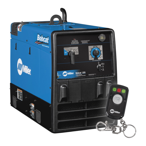
Page 34: Using Wireless Remote
� Complete Parts List is available at www.MillerWelds.com 6-2. Using Wireless Remote Place Engine Control switch in Off position when welder/generator is not in use to prevent unexpected starting. Check that all doors, panels, cov- ers, and guards are closed and se- curely in place before starting. -
Page 35: Cold Weather Engine Operation
Complete Parts List available at www.MillerWelds.com � Complete Parts List is available at www.MillerWelds.com 6-3. Cold Weather Engine Operation Ref. 236615-A Breather Icing air off. This increases engine temperature 1 Engine Control Switch — Infrequently during operation in both idle and high speed. Loaded Oil breather/pulse line icing occurs in severe �... -
Page 36: Typical Stick Welding Connections And Control Settings
(1/8 in.) Electrode: � Set Coarse Range switch to 50-150 (1/ 8”) position. � Set Fine control at 7 or higher for best results. � Miller recommends Hobart filler metals. 3/4 in. ps head wrench crescent wrench OM-286503 Page 32... -
Page 37: Typical Mig Welding Connections And Settings
� Complete Parts List is available at www.MillerWelds.com 6-5. Typical MIG Welding Connections and Settings A. Solid Wire Applications Stop engine. � This section provides general guide- lines and may not suit all applications. � The control panel shows the typical set- tings for welding with 0.035 (ER70S-3) solid wire, short circuit transfer. - Page 38 � Do a test weld. To increase arc length, increase Fine Control setting. To short- en arc length, reduce fine control setting or increase wire feed speed. � Miller recommends Hobart filler metals. 3/4 in. ps head wrench crescent wrench...
-
Page 39: Typical Mig Connections And Settings Using Weld Control And Spoolgun
Insert trigger control plug (item 11) into weld 8 Work Clamp IPM. control receptacle. Tighten threaded collar. 9 Gas Hose � Connect AC power cord (item 12) to 120 volt Miller recommends Hobart filler 10 Argon Cylinder AC receptacle on welder/generator. metals. -
Page 40: Fuel/Hour Gauge Descriptions
� Complete Parts List is available at www.MillerWelds.com 6-7. Fuel/Hour Gauge Descriptions OM-286503 Page 36... -
Page 41: Section 7 - Operating Auxiliary Equipment
� Complete Parts List is available at www.MillerWelds.com SECTION 7 – OPERATING AUXILIARY EQUIPMENT 7-1. Generator Power Receptacles Complete Parts List available at www.MillerWelds.com 250916-A / 249088-A RC1 supplies 60 Hz single-phase power at CB2 protects RC2 and CB3 protects RC3 Use GFCI protection when operating weld/power speed. -
Page 42: Gfci Receptacle Information, Resetting, And Testing
� Complete Parts List is available at www.MillerWelds.com 7-2. GFCI Receptacle Information, Resetting, And Testing Use GFCI protection when operating If a ground fault is detected, the GFCI Reset Resetting GFCI Receptacles auxiliary equipment. If unit does not button pops out, and the circuit opens to dis- If a GFCI fault occurs, stop engine and dis- have GFCI receptacles, use GFCI- connect power to the faulty equipment. -
Page 43: Simultaneous Weld And Power
� Complete Parts List is available at www.MillerWelds.com 7-3. Simultaneous Weld And Power Weld Current in Amperes Total Power in Watts 120 V Full kVA Receptacle 240 V Full kVA Receptacle Amperes Amperes 2200 3500 Complete Parts List available at www.MillerWelds.com 5200 8000 11,000... -
Page 44: Section 8 - Maintenance And Troubleshooting
� Complete Parts List is available at www.MillerWelds.com SECTION 8 – MAINTENANCE AND TROUBLESHOOTING 8-1. Routine Maintenance Stop engine before maintaining. � See Engine Manual and Maintenance Label for important start-up, service, and storage information. Service engine more often if used in severe conditions. -
Page 45: Maintenance Label
� Complete Parts List is available at www.MillerWelds.com 8-2. Maintenance Label OM-286503 Page 41... -
Page 46: Servicing Air Cleaner
� Complete Parts List is available at www.MillerWelds.com 8-3. Servicing Air Cleaner Stop engine. NOTICE – Do not run engine without air cleaner or with dirty element. Engine dam- age caused by using a damaged element is not covered by the warranty. 1 Precleaner Wash precleaner with soap and water solu- tion. -
Page 47: Overload Protection
� Complete Parts List is available at www.MillerWelds.com 8-4. Overload Protection Stop engine. Disconnect negative (-) battery cable. � Fuses F1 and F2 located on bracket behind right side panel. 1 Fuse F2 F2 protects the weld excitation winding from overload. -
Page 48: Changing Engine Oil, Oil Filter, And Fuel Filter
� Complete Parts List is available at www.MillerWelds.com 8-5. Changing Engine Oil, Oil Filter, And Fuel Filter Stop engine and let cool. 1 Oil Drain Valve Change engine oil and filter according to en- gine owner’s manual. NOTICE – Close valve and valve cap before adding oil and running engine. -
Page 49: Adjusting Engine Speed (Kohler Ch730 Carbureted Units)
Complete Parts List available at www.MillerWelds.com � Complete Parts List is available at www.MillerWelds.com 8-6. Adjusting Engine Speed (Kohler CH730 Carbureted Units) After tuning engine, check engine speeds with a tachometer (see table). If necessary, adjust speeds as follows: Start engine and run until warm. Turn Fine Control to 10. -
Page 50: Troubleshooting
� Complete Parts List is available at www.MillerWelds.com 8-7. Troubleshooting A. Welding Troubleshooting Trouble Remedy Low or no weld output; generator Check control settings. power output okay at AC receptacles. Check weld connections. Check fuse F2, and replace if open (see Section 8-4). Have Factory Authorized Service Agent check brushes, slip rings, and integrated rectifiers SR2 and SR3. - Page 51 � Complete Parts List is available at www.MillerWelds.com Trouble Remedy Erratic power output at AC Check fuel level. receptacles. Check engine speed, and adjust if necessary (see Section 8-6). Check receptacle wiring and connections. Have Factory Authorized Service Agent check brushes and slip rings. C.
- Page 52 � Complete Parts List is available at www.MillerWelds.com D. Wireless Remote Troubleshooting Trouble Remedy Fob Communication LED (1st LED) Check that the Engine Control switch is set to Run or Run/Idle blinks rapidly after start or stop se- Remove obstructions between fob and unit. quence button presses.
-
Page 53: Section 9 - Parts List
� Complete Parts List is available at www.MillerWelds.com SECTION 9 – PARTS LIST 9-1. Recommended Spare Parts Recommended Spare Parts Dia. Mkgs. Part No. Description Quantity F1, F2 169296 Fuse, Mintr Gl 25. Amp 125 Volt 215621 Fuse, 30 Amp Ato Type 276379 Switch, Oil Pressure (Kohler CH730) 190248... -
Page 54: Section 10 - Electrical Diagrams
SECTION 10 – ELECTRICAL DIAGRAMS Figure 10-1. Circuit Diagram For Welder/Generator OM-286503 Page 50... - Page 55 OM-286503 Page 51...
-
Page 56: Section 11 - Generator Power Guidelines
SECTION 11 – GENERATOR POWER GUIDELINES � The views in this section are intended to be representative of all engine-driven welder/generators. Your unit may differ from those shown. 11-1. Selecting Equipment 1 Generator Power Receptacles – Neutral Bonded To Frame 2 3-Prong Plug From Case Grounded Equipment 3 2-Prong Plug From Double Insulated... - Page 57 11-3. Grounding When Supplying Building Systems 1 Equipment Grounding Terminal 2 Grounding Cable GND/PE Use #8 AWG or larger insulated copper wire. 3 Ground Device � Use ground device as stated in electri- cal codes. Ground generator to system earth ground if supplying power to a premises (home, shop, farm) wir- ing system.
- Page 58 11-5. Approximate Power Requirements For Industrial Motors Industrial Motors Rating Starting Watts Running Watts Split Phase 1/8 HP 1/6 HP 1225 1/4 HP 1600 1/3 HP 2100 1/2 HP 3175 Capacitor Start-Induction Run 1/3 HP 2020 1/2 HP 3075 3/4 HP 4500 1400 1 HP...
- Page 59 Farm/Home Equipment Rating Starting Watts Running Watts Refrigerator or Freezer 3100 Shallow Well Pump 1/3 HP 2150 1/2 HP 3100 1000 Sump Pump 1/3 HP 2100 1/2 HP 3200 1050 11-7. Approximate Power Requirements For Contractor Equipment Contractor Equipment Rating Starting Watts Running Watts Hand Drill...
- Page 60 11-8. Power Required To Start Motor 1 Motor Start Code 2 Running Amperage 3 Motor HP 4 Motor Voltage AC MOTOR VOLTS AMPS Step 1: Find code and use table to find kVA/ CODE HP. If code is not listed, multiply running am- PHASE perage by six to find starting amperage.
- Page 61 11-10. Typical Connections To Standby Power 1. Utility Electrical 2. Transfer Switch 3. Fused Disconnect 4. Welder/Generator Service Switch (If Required) Output 5. Essential Loads Have only qualified persons perform 1 Utility Electrical Service 4 Welder/Generator Output these connections according to all 2 Transfer Switch (Double-Throw) Generator output voltage and wiring must applicable...
- Page 62 11-11. Selecting Extension Cord (Use Shortest Cord Possible) A. Cord Lengths For 120 Volt Loads Use GFCI protection when operating auxiliary equipment. If unit does not have GFCI receptacles, use GFCI-protected extension cord. Do not use GFCI receptacles to power life support equipment. Maximum Allowable Cord Length In ft (m) for Conductor Size In AWG (mm Current (Amperes)
-
Page 63: Section 12 - Stick Welding (Smaw) Guidelines
SECTION 12 – STICK WELDING (SMAW) GUIDELINES tools/ 12-1. Stick Welding Procedure wrench crescent wrench allen_set flathead philips head wrench crescent wrench Weld current starts when electrode Tools Needed: touches workpiece. Weld current can damage elec- tronic parts in vehicles. Discon- nect both battery cables before welding on a vehicle. - Page 64 12-2. Electrode And Amperage Selection Chart 6010 DEEP 3/32 MIN. PREP, ROUGH HIGH SPATTER 6011 DEEP 6010 5/32 & 6013 EP,EN GENERAL 3/16 6011 7/32 SMOOTH, EASY, 7014 EP,EN FAST 1/16 LOW HYDROGEN, 7018 5/64 STRONG 3/32 FLAT SMOOTH, EASY, 7024 EP,EN 6013...
- Page 65 12-4. Positioning Electrode Holder 1 End View Of Work Angle Groove Welds 2 Side View Of Electrode Angle After learning to start and hold an arc, prac- tice running beads of weld metal on flat 10 -30 10 -30 plates using a full electrode. Hold the electrode nearly perpendicular to the work, although tilting it ahead (in the di- rection of travel) will be helpful.
- Page 66 12-7. Conditions That Affect Weld Bead Shape Electrode Angle � Weld bead shape is affected by elec- trode angle, arc length, travel speed, and thickness of base metal. 1 Angle Too Small 2 Correct Angle 3 Drag 4 Angle Too Large 5 Too Short 6 Normal Arc Length...
- Page 67 12-9. Welding Lap Joints 1-1. Welding Lap Joints 1 Electrode 2 Single-Layer Fillet Weld 1-1. Welding Lap Joints Move electrode in circular motion. 3 Multi-Layer Fillet Weld Weld a second layer when a heavier fillet is needed. Remove slag before making anoth- er weld pass.
- Page 68 12-11. Welding T-Joints 1-3. Welding T-Joints 1/16 in. (1.6 mm) 1 Electrode 2 Fillet Weld Keep arc short and move at definite rate of speed. Hold electrode as shown to provide fusion into the corner. Square edge of the weld surface. For maximum strength weld both sides of up- 1-3.
- Page 69 Excessive Spatter - scattering of molten metal particles that cool to solid form near weld bead. Possible Causes Corrective Actions Amperage too high for electrode. Decrease amperage or select larger electrode. Arc length too long or voltage too high. Reduce arc length or voltage. Incomplete Fusion - failure of weld metal to fuse completely with base metal or a preceding weld bead.
- Page 70 Distortion - contraction of weld metal during welding that forces base metal to move. Illustration: Base metal moves in the direction of the weld bead. Possible Causes Corrective Actions Excessive heat input. Use restraint (clamp) to hold base metal in position. Make tack welds along joint before starting welding operation.
-
Page 71: Section 13 - Gmaw Welding (Mig) Guidelines When Using A Voltage-Sensing Feeder
SECTION 1 GMAW WELDING (MIG) GUIDELINES WHEN SECTION 13 – GMAW WELDING (MIG) GUIDELINES WHEN USING A VOLTAGE-SENSING FEEDER USING A VOLTAGE-SENSING FEEDER 13-1. Typical GMAW (MIG) Process Connections Using A Voltage-Sensing Wire Feeder Weld current can damage elec- tronic parts in vehicles. Discon- nect both battery cables before welding on a vehicle. - Page 72 Holding And Positioning Welding Gun 13-2. Holding And Positioning Welding Gun � Welding wire is energized when gun trigger is pressed. Before lowering hel- met and pressing trigger, be sure wire is no more than 1/2 in. (13 mm) past end of nozzle, and tip of wire is posi- tioned correctly on seam.
- Page 73 13-3. Conditions That Affect Weld Bead Shape Gun Angles and Weld Bead Profiles � Weld bead shape depends on gun an- gle, direction of travel, electrode exten- sion (stickout), travel speed, thickness of base metal, wire feed speed (weld current), and voltage. 1 Push 2 Perpendicular 3 Drag...
- Page 74 13-4. Gun Movement During Welding � Normally, a single stringer bead is sat- isfactory for most narrow groove weld joints; however, for wide groove weld joints or bridging across gaps, a weave bead or multiple stringer beads works better. 1 Stringer Bead - Steady Movement Along Seam 2 Weave Bead - Side To Side Movement Along Seam...
- Page 75 13-7. Troubleshooting – Excessive Spatter Excessive Spatter - scattering of molten metal particles that cool to solid form near weld bead. Possible Causes Corrective Actions Wire feed speed too high. Select lower wire feed speed. Voltage too high. Select lower voltage range. Electrode extension (stickout) too long.
- Page 76 13-10. Troubleshooting – Lack Of Penetration Lack Of Penetration - shallow fusion between weld metal and base metal. Possible Causes Corrective Actions Improper joint preparation. Material too thick. Joint preparation and design must provide access to bottom of groove while maintaining proper welding wire extension and arc characteristics.
- Page 77 13-14. Troubleshooting – Distortion Distortion - contraction of weld metal during welding that forces base metal to move. Illustration: Base metal moves in the direction of the weld bead. Possible Causes Corrective Actions Excessive heat input. Use restraint (clamp) to hold base metal in position. Make tack welds along joint before starting welding operation.
- Page 78 13-16. Troubleshooting Guide For Semiautomatic Welding Equipment Problem Probable Cause Remedy Wire feed motor operates, but wire does not Too little pressure on wire feed rolls. Increase pressure setting on wire feed rolls. feed. Incorrect wire feed rolls. Check size stamped on wire feed rolls, re- place to match wire size and type if necessary.
-
Page 79: Warranty
Effective January 1, 2020 (Equipment with a serial number preface of NA or newer) This limited warranty supersedes all previous Miller warranties and is exclusive with no other guarantees or warranties expressed or implied. LIMITED WARRANTY − Subject to the terms and conditions Supplied Air Respirator (SAR) Boxes and Panels below, Miller Electric Mfg. - Page 80 File a claim for loss or damage during For International Locations Visit shipment. www.MillerWelds.com For assistance in filing or settling claims, con- tact your distributor and/or equipment manu- facturer’s Transportation Department. ORIGINAL INSTRUCTIONS – PRINTED IN USA © 2020 Miller Electric Mfg. LLC 2020-02...
Need help?
Do you have a question about the Bobcat 225 and is the answer not in the manual?
Questions and answers
I am looking for a replacement air filter box (mine is missing) for Miller bobcat 225 NT (Kohler) Also need the air filter as well. Thanks
You can find a replacement air filter for a Miller Bobcat 225 NT with a Kohler engine in the Tune-up & Filter Kit (part number 230015) or separately as the Air Filter Element (part number 230016), as listed in the manual.
This answer is automatically generated