Advertisement
Quick Links
88 5130 381
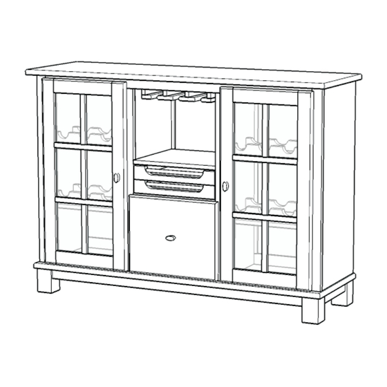
Wine Cabinet
IMPORTANT NOTE
Carefully remove all the parts from the carton and put
them individually on a soft cloth to prevent scratches
or other damages occuring to the wood parts.
We have taken great care in the design of this
product and request that you carefully and strictly
follow our assembly instructions to ensure a
completed product as it was designed.
Unit Part List
H.
Upper Back Stretcher
1 pc.
I.
Front Rail
1 pc.
J.
Lower Back Stretcher
1 pc.
Hardware List
Small
Hex Wrench
1 pc.
Head Cap Bolt
20 pcs. (+1 extra)
For assembly see instructions in carton 88 5130 382
Tools required for assembly : Phillips screwdriver
Casual Attire For Today's Home
A.
Top
1 pc.
Cam Lock
Hex Wrench
18 pcs.(+1 extra)
1 pc.
Wood Screw (long)
for Drawer
Cam Lock Screw
12 pcs. (+1 extra)
18 pcs.(+1 extra)
O.
Base
1 pc.
Wood Screw
Wood Screw
for Back Panel
for Drawer
12 pcs. (+1 extra)
4 pcs. (+1 extra)
Adjustable Pin
16 pcs. (+2 extra)
G.
Back Piece
2 pcs.
Machine Screw
3 pcs.
Pull Handle
3 pcs.
Advertisement

Related Manuals for EefaCo.Store 88 5130 381


Summary of Contents for EefaCo.Store 88 5130 381
- Page 1 88 5130 381 Wine Cabinet IMPORTANT NOTE Carefully remove all the parts from the carton and put them individually on a soft cloth to prevent scratches or other damages occuring to the wood parts. We have taken great care in the design of this...
-
Page 2: Important Note
1 pc. to complete assembling drawers) 1 pc. 1 pc. Also need the following from carton 88 5130 381 : Hardware List in carton 88 5130 381 Hardware List in carton 88 5130 381 Part List in carton 88 5130 381... - Page 3 Assembly Instructions 2/5 IMPORTANT Do not tighten up all the screws until each part is properly assembled. You should keep Hex Wrench in the safe place as you may need to tighten up the Head Cap Bolts in the future. Cam Lock Screw STEP 1 Put Cam Lock Screws into the...
- Page 4 Assembly Instructions 3/5 STEP 3 Attach Fixed Shelf (L) to the Middle Panel (D) and Middle Panel (E) using Cam Locks. Cam Lock Cam Lock Head Cap Bolt STEP 4 Cam Lock Place unit in Step 3 onto the unit in step 2. Attach Rack (N) to the unit with Head Cap Bolts.
- Page 5 Assembly Instructions 4/5 Wood Screw Wood Screw STEP 5 Head Cap Bolt Remove Wood Screw from Door (R) and (S). Machine Screw Slide Glass (T) into the doors frame Tighten Wood Screws as shown. (Figure 2) (Figure 1) STEP 6 Turn the unit back to its upright position.
-
Page 6: Part List
Assembly Instructions 5/5 Drawer (U) STEP 1 Attach U1 to U3 and U4, using a Phillips screwdriver and long wood screws (4X) tighten halfway. Attach U2 to U3 and U4 using Figure 1 long wood screws (4X), tighten halfway. (see Figure 1) MAKE SURE ROLLER IS ON THE BACK STEP 2...
Need help?
Do you have a question about the 88 5130 381 and is the answer not in the manual?
Questions and answers