Table of Contents
Advertisement
Quick Links
88 5537 121
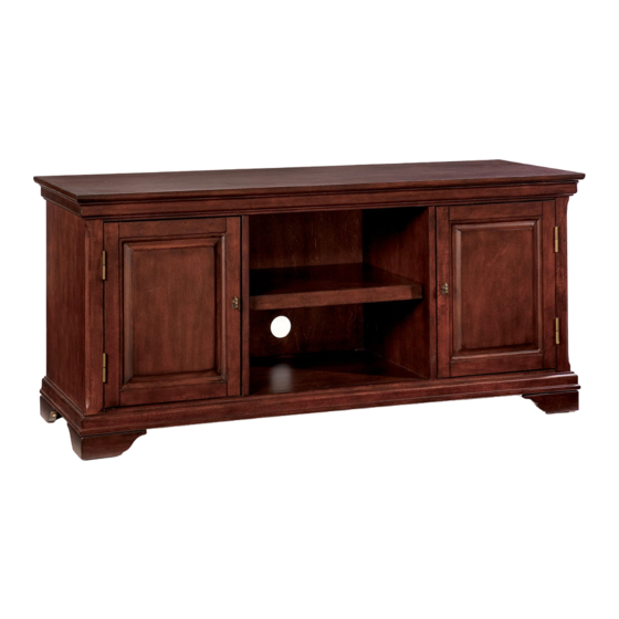
The Lafayette
Entertainment Stand
Carefully remove all the parts from the carton and put
them individually on a soft cloth to prevent scratches
or other damages occuring to the wood parts.
We have taken great care in the design of this
product and request that you carefully and strictly
follow our assembly instructions to ensure a
completed product as it was designed.
Part List
A.
Top
1 pc.
E.
Base
1 pc.
G.
Plinth
1 pc.
Hardware List
Hex Wrench
Cam Lock Screw
1 pc.
22 pcs.(+1 extra)
Head Cap Bolt
Cam Lock
8 pcs. (+1extra)
22 pcs.(+1 extra)
For assembly see instructions in carton 88 5537 122
Tools required for assembly : Phillips screwdriver
Wood Screw
Wood Screw
for Back Panel
for Magnet
12 pcs.(+1 extra)
4 pcs.(+1 extra)
Magnet
2 pcs.
Casual Attire For Today's Home
F.
Front Rail
1 pc.
M.
Shelf
2 pcs.
Steel Plate
Machine Screw
2 pcs.
for Pull Handle
Attachment
1 pc.
Adjustable Pin
Nail
12 pcs.(+1 extra)
2 pcs.(+1 extra)
Pull Handle
2 pcs.
Advertisement
Table of Contents

Related Manuals for EefaCo.Store Lafayette 88 5537 121


Summary of Contents for EefaCo.Store Lafayette 88 5537 121
- Page 1 88 5537 121 The Lafayette Entertainment Stand IMPORTANT NOTE Carefully remove all the parts from the carton and put them individually on a soft cloth to prevent scratches or other damages occuring to the wood parts. We have taken great care in the design of this product and request that you carefully and strictly follow our assembly instructions to ensure a Casual Attire For Today's Home...
- Page 2 88 5537 122 The Lafayette Entertainment Stand IMPORTANT NOTE Carefully remove all the parts from the carton and put them individually on a soft cloth to prevent scratches or other damages occuring to the wood parts. We have taken great care in the design of this product and request that you carefully and strictly follow our assembly instructions to ensure a Casual Attire For Today's Home...
- Page 3 Assembly Instructions 2/5 IMPORTANT Do not tighten up all the screws until each part is properly Magnet assembled. You should keep Hex Wrench in a safe place as you may need to tighten up the Head Cap Bolts in the future. STEP 1 Attach 2X Magnets to Front Rail (F) by using Wood Screws (see Figure 1).
- Page 4 Assembly Instructions 3/5 STEP 2 Attach Middle Panel (D1) and (D2) onto Base (E) with Cam Locks. Cam Lock Cam Lock Screw Cam Lock Screw Cam Lock Head Cap Bolt STEP 3 Attach Plinth (G) to the unit with Cam Locks. Head Cap Bolt Attach Side Panel (B) and (C) to the unit with Cam Locks.
- Page 5 Assembly Instructions 4/5 Nail Steel Plate Figure 4 Figure 5 STEP 4 Slide Back Panels (H) and (I) into place. Assemble Pull Handles to Doors (J) and (K) with Machine Screws. Use the Steel Plate to firmly push the nail through the hole in the Pull Handle and into the pre-drilled hole in the door (see Figure 4).
- Page 6 Assembly Instructions 5/5 Cam Lock Adjustable Pin STEP 5 Place Top (A) onto the unit, using Cam Locks. Insert Adjustable Pins into side panels and middle panels at the desired level. Place Shelves (L) and (M) into position. STEP 6 Insert 12X Wood Screws from the back of the unit, tighten up all the Wood Screws (see Figure 6).
Need help?
Do you have a question about the Lafayette 88 5537 121 and is the answer not in the manual?
Questions and answers