
Subscribe to Our Youtube Channel
Related Manuals for OM POWER OM2002+


Summary of Contents for OM POWER OM2002+
- Page 1 OM2002+ SOLID STATE 145 MHz POWER AMPLIFIER User Manual OM POWER, s. r. o. 930 30 Báč 126 E-mail : om-power@om-power.com SLOVAKIA Web : www.om-powwer.com...
- Page 2 This product is covered by 3 years of warranty period. We wish you many years trouble-free use of this equipment, lot of fun and successful connections in the world of amateur radio. The OM POWER Team Conventions used in this manual DANGER / WARNING : Information to prevent injury to yourself when completing a task.
-
Page 3: Table Of Contents
TABLE OF CONTENTS 1. GENERAL INFORMATION 1.1. Introduction 1.2. Specification 1.2.1. Parameters 1.2.2. Protection Circuits 2. SAFETY INSTRUCTIONS 3. GENERAL DESCRIPTION 3.1. Front and Rear Panel 3.2. HF Part 3.3. Power Supply 3.4. Safety Devices 4. INSTALLATION 4.1. Grounding 4.2. Coaxial Cable... - Page 4 4.3. Control Cable 4.4. Main Supply 4.5. Cooling 5. OPERATION 5.1. Operation Elements 5.2. Preparing for Use 5.3. Setup Menu 5.3.1. Language selection 5.3.2. Display contrast 5.3.3. Display delay 5.3.4. Bias switch 5.3.5. Preamplifier delay 5.3.6. Bias current 5.4. Operating Mode 6.
- Page 5 6.2. Fuses 6.3. Cleaning 7. BLOCK DIAGRAM 8. TIMING...
-
Page 6: General Information
1.1. Introduction The OM Power model OM2002+ is a single band, solid state amplifier, designed for duty operation on 2 meter’s amateur band with all modes and no time limit. It is equipped with a Freescale high rugged N-channel double MOSFETs. - Page 7 Power Gain Typically 20 dB Output impedance 50 Ohm unbalanced Maximum output SWR 1,9 : 1 for full output power 1800W SWR protection: Automatic switching to STBY , when reflected power is 180W or higher Intermodulation distortion - 32 dBc Suppression of harmonics <...
-
Page 8: Protection Circuits
1.2.2. Protection Circuits There is several special protection circuits used in the amplifier. They are activated when one or more of next parameters exceed defined values or some unwanted occasion occurs. Output power too high Reflected power too high ... -
Page 9: Safety Instructions
Safety Instructions Before you will start to install and operate power amplifier, read carefully next safety instructions! AVOID CHILDREN to play around PA or to touch power amplifier or connected cables in working condition, or to push anything into the holes! Never turn the amplifier on without the upper lid in place. - Page 10 The amplifier must be installed in such a way that free flow of hot air from inside is allowed. The amplifier must not be installed in a constrained surrounding (i.e. tight shelves etc.) The amplifier must be properly grounded during operation. During operation the amplifier must be installed in such a way that the rear panel will stay accessible.
-
Page 11: General Description
General description 3.1. Front and Rear Panel Main switch (green) on the right side and OLED display are visible on the front panel. After switch PA ON, the display lights up in couple of seconds and shows the controls and indicators. - Page 12 RF Output See Note RF Input Grounding Point Mains Plug Power Supply Cooler inside...
- Page 13 - Local Area Network connection for REMOTE CONTROL of PA PREAMP - RCA Phono, +12V / 100mA for an external RX preamplifier switching If you are using an older transceiver or transmitters without time delay, we recommend to connect the PA in such a way that the transmit/receive switch (foot switch for example) is connected with the KEY IN socket of the amplifier.
- Page 14 Top view on the power amplifier Input board with output coax relay together with SWR board is visible on the right upper side. Left side shows the main RF part – two boards with MOSFETs amplifiers, everyone for max. 1 kW of output power.
-
Page 15: Hf Part
3.2. HF part OM2002+ power amplifier was designed to achieve the RF performance of the MOSFETs, when applied to the 144 – 148 MHz frequency band. Design was tuned for performance at 1800W CW output, 50VDC. It consists of „no tune“ distributed element matching circuits designed to be as small as possible. For operating it is important that adequate heat sinking was provided in the design. -
Page 16: Power Supply
The coaxial transformer turns ratio was chosen to meet required impedance level and the length of the coax was tuned to achieve maximum efficiency and maximum power transfer between the device and its load impedance. Low Pass Filter is installed behind the amplifier to attenuate harmonics. - Page 17 Main power supply contains special soft start circuits, uses its own fan, which is visible from the rear side of the PA. It has its own overloading protection and logic to control fan speed. Power amplifier should be connected to any external source of AC in the range from 100 VAC to 277 VAC, from 45 to 60 Hz.
-
Page 18: Safety Devices
.4. Safety Devices Control and monitoring circuits ensure control and safety during malfunctions of the PA. These are on the Control board and the Protection board. Control board is located behind the front panel. Protection board is visible on the right hand side of PA, close to the input/output relay. Protection board with Input circuits. -
Page 19: Installation
4. Installation Read this chapter carefully prior starting with installation. Before unpacking inspect shipping carton first, if it is not damaged. Keep all of packing parts for possible future shipment. Check unpacked power amplifier. If you find some damaging, contact your dealer immediately to keep full warranty. During installation go step by step according to next parts. -
Page 20: Coaxial Cable
Connect your transceiver to the same grounding system of your shack carefully! Use minimum length of cables and make sure that the connections are both physically and electrically sound. With poor grounding, you may risk damaging to your equipment, having problems with TVI/BCI or your transmitted signal may be distorted. -
Page 21: Main Supply
Amplifier uses one coaxial relay for the output. It has to be switched earlier than HF is applied (cold switching). Modern transceivers they have a time delay between PTT switching and power output. Sufficiently robust coaxial relay is using for TX/RX switching. 4.4. -
Page 22: Cooling
Be sure that your power system is correctly wired and properly rated! To use adequately sized and connected grounding system is also very important. 4.5. Cooling The amplifier must be installed in such a way that free flow of hot air from the amplifier is allowed. Do not obstruct air intake and exhaust areas of the PA. -
Page 23: Operation
5. Operation Before switching PA on, make sure that amplifier is grounded, antenna or dummy load is connected, and power cord is putted to the outlet. Do not turn PA on for at least 2 hours after unpacking it and moving in its operating location. Especially when amplifier was moved from a cold place to a warm one, because not visible condensation may develop inside, and this could result in damage of the PA. -
Page 24: Operation Elements
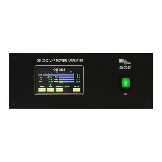
5.1. Operation Elements After switch PA ON (green switch on the front panel) main supply will be activated, the touchscreen lights up and shows the controls and indicators. They are very intuitive. There are 4 yellow touch buttons visible on the screen. Above the first three buttons (from the left side) their status should be displayed. -
Page 25: Preparing For Use
Contest fan speed is selected PA is in the operation mode External preamplifier is ON 5.2. Preparing for use After turning on the power switch on the front panel power amplifier will automatically go into standby mode. We recommend to start preparation for operation with SETUP menu. Firstly it allows you to set the language, then to set some of the basic parameters. -
Page 26: Setup Menu
5.3. Setup Menu In the setup mode you can set the basic parameters of the display and amplifier. In the first step choose language. Touch SETUP on the screen. Setup menu is displayed. Touch LANG. -
Page 27: Language Selection
5.3.1. Language selection The language selection screen is displayed. Touch on the corresponding flag to select language. Screen will go automatically back to the Setup Menu. Or, if you do not want to change language, touch BACK. 5.3.2. Display contrast Touch CONT from Setup screen. -
Page 28: Display Delay
5.3.3. Display delay Display will not turns OFF Display turns OFF after 10 sec. Display turns OFF after 1 min (max.) 5.3.4. Bias switch Electronic Bias Settings (EBS) is one of significant feature of the power amplifier. It allows to set low MOSFETs drain current (abt. -
Page 29: Preamplifier Delay
To deactivate EBS you have to set Bias switch to OFF. I such a case bias value immediately after pressing the PTT will be high. Touch BIAS from the Setup screen. Use ON/OFF to set bias working condition. Then touch BACK. Screen will go automatically back to the Setup Menu. -
Page 30: Bias Current
Touch PREAM from Setup screen. Use UP/DOWN to set delay value (0- 200ms). Then touch SAVE. Screen will go automatically back to the Setup Menu. Or, if you do not want to change delay, touch BACK. 5.3.6. Bias current Touch CURR to see both levels of bias current for both MOSFETs. In couple of seconds you will see the values of drain current in the four lines. -
Page 31: Operating Mode
5.4. Operating mode In STBY the amplifier is in bypass-mode and your transceiver is directly connected to the antenna. Maximum allowed power in bypass mode is 100 Watts! Passing RF power is not measured and displayed if PA is either in standby mode or turned OFF. Touch the OP/STBY button to activate operating mode. - Page 32 Picture shows input power of 0.5 W, output power 206 W. Power gain from input to output of the PA is 26.1 dB. You can also read other important parameters on the display – MOSFETs voltage, MOSFETs current, reflected power, SWR and temperature. Depending on the reflected power you can consider quality of your antenna (impedance matching).
- Page 33 If all looks ok, you can increase RF power from the transceiver slowly and check important parameters of the PA. Do not exceed the output power of 1800 watts in CW operation mode and about 1500 watts in SSB, AM, FM and digi operation mode even if more is reachable.
- Page 34 If something happened with PA loading (for example), protection circuit detects increasing of VSWR (reflected power). If this parameter exceed the limit value, fault condition appears and PA will be immediately blocked. Top picture shows such a situation. Fault LED is ON, transmitting is blocking.
-
Page 35: Maintenance
Maintenance 6.1. Fault conditions If a fault condition appears during the operation of the amplifier, the safety circuits of OM2002+ will react, the FAULT LED lights. There are several fault or warning messages possible to appear on the display (under the fault LED) in abbreviated form, when some of the protection will be activated. - Page 36 If the output power of the PA exceeds the limit value, „FWD” fault message appears on the display, transmitting will be blocked. Fault LED will lights. To be able to transmit again, you have to remove the cause of the error (decrease the input power).
- Page 37 In the case of the main power supply failure, or when voltage drops below 42 volts, fault message „Voltage“ appears, transmitting will be blocked. We recommend to switch PA immediately OFF in such a case. You have to contact manufacturer or your dealer for assistance. When the amplifier reaches inside temperature of 75 deg.
- Page 38 6.2. Fuses There are no fuses reachable from outside or from inside of the PA. If you turn the power amplifier ON and no LED will be illuminated, display stays dark, check mains first, and then contact your dealer. In such a case main power supply failure occurred, probably.
- Page 39 Block diagram...
- Page 40 Timing KEY IN KEY OUT BIAS 5 10 time in ms INPUT Switching time 20ms IN RELAY 15ms OUT OUTPUT Switching time 20ms IN RELAY 15ms OUT...
- Page 41 In the case if LNA is active (PREAMPLIFIER ON) KEY IN KEY OUT BIAS T+10 INPUT Switching time 20ms IN relay 15ms OUT OUTPUT Switching time 20ms IN relay 15ms OUT...
Need help?
Do you have a question about the OM2002+ and is the answer not in the manual?
Questions and answers