
Related Manuals for OM POWER OM2200A


Summary of Contents for OM POWER OM2200A
- Page 1 OM2200A MADE IN SLOVAKIA SHORTWAVE POWER AMPLIFIER WWW.OM-POWER.COM OM POWER, s.r.o. 93030 Báč 126 SLOVAKIA Contact : +421 905 321 410 e-mail : om-power@om-power.com...
-
Page 2: Table Of Contents
TABLE OF CONTENTS GENERAL INFORMATION Introduction ………………………………………………………………... 1.1. Specification ……………………………………………………………..1.2. 1.2.1. Parameters …………………………………………………………………. 1.2.2. Protection Circuits ………………………………………………………… 1.2.3. Indicators ………………………………………………………………….. ………………………………………………. SAFETY INSTRUCTIONS ………………………………………………… GENERAL DESCRIPTION HF part ……………………………………………………………………. . 7 3.1. Power Supply ……………………………………………………………… 8 3.2. Safety Devices …………………………………………………………….. 3.3. - Page 3 Icom ……………………………………………………….. 31 7.7. Example for connection USB micro KEYER II with Yeasu or ELECRAFT ……………………………………………. 32 7.8. Example of connection PA with MicroHAM MKII, (MK2R+ etc ) with CI-V output ..................7.9. Block Diagram of OM2200A Power Amplifier)........
-
Page 4: General Information
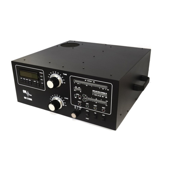
GENERAL INFORMATION 1.1. Introduction The OM Power model OM2200A is a fully automatic power amplifier, designed for use on all short wave amateur bands from 1.8 to 29.7 MHz (including WARC bands) and all modes. It is equipped with one FU728F ceramic tetrode. -
Page 5: Protection Circuits
1.2.2. Protection Circuits There are 8 special protection circuits used in the amplifier. They are activated when one or more of next parameters exceed defined values or some unwanted occasion occurs. VSWR too high Anode current too high ... -
Page 6: Safety Instructions
The amplifier reaches optimal parameters in 2 phase’s system, if you do not have 2 phases, connect both mains cords into the same phase. The OM2200A amplifier is neither to be used in a WET or HUMID environment nor to be exposed to RAINFALL! - Page 7 The amplifier must be properly grounded during operation During operation the amplifier must be installed in such a way that the rear side remains accessible. The amplifier is an A category product. In a household it can influence other electric appliances.
-
Page 8: General Description
The output of the amplifier is a Pi-L circuit. The ceramic capacitor for TUNE and LOAD are divided. This enables the amplifier to be tuned exactly and makes it possible to easily return to the previously set positions after band changes. Top view on the opened OM2200A FU728F PWR meter... -
Page 9: Power Supply
3.2. Power Supply 3 kVA . A soft start is provided The power supply consists of toroidal transformer and rectifier block using relays and resistors. The high anode voltage is made by combining 8 x 420 V (total 3300V DC) @ 1.5A. Each has its own rectifier and filter. -
Page 10: Coaxial Cable
During transmitting the middle pin is connected to the ground. The relays of the OM2200A have to be switched earlier than HF is applied (cold switching). Modern transceivers they have a time delay between PTT switching and power output. - Page 11 If you are using and older transceiver or transmitters without time delay, we recommend to connect the PA in such a way that the transmit/receive switch (foot switch for example) is connected with the KEY IN socket of the amplifier. The KEY OUT socket is to be connected with the PTT socket at the transceiver.
- Page 12 BYPASS COM Connector (5.5/2.1mm) allows you to connect an external 12V DC power supply (rated at 200mA max.), which allows independent communication between the PC and the TCVR. It means the ability to communicate even if the PA is turned OFF. External source is separated from the internal supplying;...
-
Page 13: Mains Supply
13. GND 14. BPF 160m 15. BPF 80m 16. BPF 40m 17. BPF 30m 18. BPF 20m 19. BPF 17m 20. BPF 15m 21. BPF 12m 22. BPF 10m 23. COMMON BPF port 24. NC 25. GND 4.4. Mains Supply Be sure you got PA with properly terminated line cable, corresponding with your power system’s outlet. -
Page 14: Operation
OPERATION Before switching PA on, make sure that amplifier is grounded, antenna or dummy load is connected, line cord is putted to the outlet. Before switching PA on, check all connections between PA and TCVR. Do not turn PA on for at least 2 hours after unpacking it and locating in its operating location. - Page 15 TUNE - Anode capacitor for tuning, tuning of higher frequencies to "0", lower frequencies to „100“. LOAD - Output capacitor tunes antenna load resistance to amplifier. Capacity is low at „100“ and high at "0" on the scale. OFF - You switch off the amplifier by pressing this button.
-
Page 16: Configuration Of Power Amplifier
the transceiver. When changing the BAND – INHIBIT will stay lit until the KEY IN is released and the tuning process will start. After that PA is automatically ready for operation. ANT, ANT1, ANT2 The amplifier is capable of automatic antenna switching (ie. 80m CW and 80m SSB can be split between two antennas). -
Page 17: Tcvr Support Settings
5.2.1. TCVR Support Settings Supported transceivers: ICOM, ELECRAFT, KENWOOD, TEN-TEC , ORION, YAESU. Press SET button and scroll using UP / DWN to CHOOSE TCVR. Confirm CHOOSE TCVR by pressing SET again and scroll UP / DWN to your transceiver type. Confirm the selection by pressing SET. -
Page 18: Connection With No Supported Tcvrs
ICOM format through the CI-V output. Then the PA will be connected in the following configuration: JST-245 <> DB37- JST-245 cable <> MKII ( or other device which has a CI-V output ) <> PC. OM2200A is connected to the CI-V output of the CI-V device (MicroHam for example). Example of communication 5.2.3. -
Page 19: Antenna Switching Menu
5.2.4. Antenna Switching Menu If you have 3 party external antenna switch connected to your amplifier ( i.e. MicroHAM TEN SWITCH), you need to configure the assignment of each port to a specific band /or antenna. By pressing SET and scrolling to ANTENNA SETTINGS and confirming by SET you get current band and its antenna selection. -
Page 20: Loading Factory Default Settings
TX while tuning using ALC control (mainly while operating FM /RTTY/ AM). The ALC Input of your transceiver should be connected to the ALC Out of OM2200A. Using SET and scrolling UP / DWN select SET MUTE and confirm it by SET. Then configure MUTE LEVEL for each band so it results in no power being transmitted by TX when performing TUNE procedure. -
Page 21: Lcd Settings Menu
5.2.8. LCD Settings Menu By pressing SET and scrolling UP / DWN and selecting LCD CONTRAST (Confirming by SET) and pressing Up or DWN you can vary the Contrast of the LCD display. Press SET for confirm the setting. 5.2.8. Operation in MANUAL mode To enter Manual mode of the PA please press MAN. -
Page 22: Tuning Of Power Amplifier
5.3. Tuning of Power Amplifier The OM2200A amplifier is operated in class AB. Thus it’s possible to obtain a maximum output power at excellent linearity. For this purpose the amplifier has to be tuned carefully. Before starting tuning you have to check if the right antenna or a 50 Ohms load... - Page 23 1. Set the multimeter switch to the HV position 2. Set the OPR/STBY switch to the STBY position 3. Press the ON button The amplifier is prepared for operation with the following automatic steps: Toroidal transformers are switched on step by step. ...
-
Page 24: Tuning Adjustment
5.3.3. Tuning Adjustment Entering the TUNE mode is done by pressing the TUNE button. The OM2200A then switches the transceiver to RTTY and sets the frequency to corresponding segment. By changing the values of TUNE and LOAD capacitors we tune the PA as per manual tuning instructions (see 5.3.2.). -
Page 25: Maintenance
Should a fault condition appear during the tuning or operation of the amplifier, the safety circuits of OM2200A will react. The amplifier will be turned to STBY mode. After approx. 4 sec the control circuits will switch the amplifier back to OPR. -
Page 26: Fuse Replacement
- zero output power during tuning HV + IP - tuning fault, incorrect tuning of the Pi-L output circuit In case your OM2200A amplifier is not working correctly, please contact the manufacturer or your dealer. Manufacturer’s contacts: OM POWER, s.r.o. -
Page 27: Cleaning
Do not open the amplifier for cleaning. Outer surface may be safely accomplished by using piece of soft cotton cloth moistured with clean water or window cleaner. NOTICE Next examples taken from OM2500A model are valid also for OM2200A model. -
Page 28: Appendix
APPENDIX 7.1. Example of connection for Icom... -
Page 29: Example Of Connection For Elecraft
7.2. Example of connection for ELECRAFT... -
Page 30: Example Of Connection With Yaesu
7.3. Example of connection with Yeasu... -
Page 31: Example Of Connection With Antenna Switch And Bpf
7.4. Example of connection with antenna switch and BPF... -
Page 32: Example Of Connection Usb Micro Keyer Ii With Ic7800 Or Ic7700
7.5. Example of connection USB micro KEYER II with IC7800 or IC7700... -
Page 33: Example Of Connection Usb Micro Keyer Ii With Another Icom
7.6. Example of connection USB micro KEYER II with another Icom... -
Page 34: Example For Connection Usb Micro Keyer Ii With Yeasu Or Elecraft
7.7. Example for connection USB micro KEYER II with Yeasu or ELECRAFT... -
Page 35: Example Of Connection Pa With Microham Mkii, (Mk2R+ Etc ) With Ci-V Output
7.8. Example of connection PA with MicroHAM MKII, (MK2R+ etc ) with CI-V output... -
Page 36: Block Diagram Of Om2200A Power Amplifier)
7.9. Block Diagram of the OM2200A Power Amplifier...
Need help?
Do you have a question about the OM2200A and is the answer not in the manual?
Questions and answers