Table of Contents
Advertisement
Quick Links
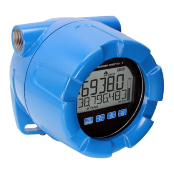
PD6938 Ex-Proof & I.S. Pulse Input
Instruction Manual
•
Fully-Approved Explosion-Proof & Intrinsically Safe Pulse Input Flow Rate/Totalizers
•
NPN Open Collector, PNP, TTL, Switch Contact,
Sine Wave (Magnetic Pickup Coil), or Active Square Wave Inputs
•
Top Display: Five 12-Segment Alphanumeric Characters, 0.7" (17.8 mm)
•
Bottom Display: Eight 14-Segment Alphanumeric Characters, 0.4" (10.2 mm)
•
Display Mountable at 0°, 90°, 180°, & 270° (No Tools Required)
•
CapTouch Through-Glass Button Programming with Normal and Delayed Modes
•
Red Backlight for Alarm Conditions, Enable and Disable Backlight from Menu
•
8-Digit Total & Grand Total Display, Up to 13 Digits Using Both Lines
•
Display Rate & Total Simultaneously
•
Bi-Directional Flow Detection Via Digital Input
•
Non-Resettable Grand Total
•
Display Previous Total and Previous Grand Total with Time-of-Day Reset Feature
•
Reset Total / Grand Total with CapTouch Button, Digital Input, or Time-of-Day Feature
•
Automatic or Manual Batch Control
•
K-Factor Calibration or Scaling with Up to 32-Point Linearization
•
Gate Function for Rate Display of Slow Pulse Rates
•
(2) Open Collector Outputs Standard; Assignable to Pulse, Alarm, Timer, or Stopwatch
•
(2) Optional Solid-State Relays; Assignable to Alarm, Sample, Timer, Batch Control, or Stopwatch
•
Optional Isolated 4-20 mA Analog Output
•
Free PC-Based MeterView XL USB Programming Software
•
9-30 VDC, Battery, or 4-20 mA Output Power Options
•
Battery-Powered Momentary Backlight & Display Sleep and Off Modes to Extend Battery Life
•
Modbus RTU RS-485 Communications Standard on DC & Battery Powered Models
•
On-Board Data Logging of up to 2,032 Records and Modbus
•
Password Protection for Settings, Total & Grand Total
•
CSA Certified for Explosion-Proof / Dust-Ignition Proof / Flame-Proof
•
ATEX and IECEx Certified as Intrinsically Safe and Explosion-Proof
•
Operating Temp Range: -40 to 75°C (-40 to 167°F)
•
Installation Temp Range: -55 to 75°C (-67 to 167°F)
•
Conformal Coated PCBs for Dust & Humidity Protection
•
Flange for Wall or Pipe Mounting; Loop for Stainless Steel Tag; Holes for Tamper-Proof Seal
•
Explosion-Proof Aluminum & Stainless Steel Enclosures with 1", 3/4", or M20 Connections
•
3-Year Warranty
PRECISION DIGITAL CORPORATION
233 South Street • Hopkinton MA 01748 USA
Tel (800) 343-1001 • (508) 655-7300
www.predig.com
Flow Rate/Totalizer
IECEx
®
Accessible Data
Advertisement
Table of Contents
Troubleshooting

Subscribe to Our Youtube Channel
Related Manuals for Precision Digital Corporation PD6938


Summary of Contents for Precision Digital Corporation PD6938
- Page 1 PD6938 Ex-Proof & I.S. Pulse Input Flow Rate/Totalizer Instruction Manual IECEx • Fully-Approved Explosion-Proof & Intrinsically Safe Pulse Input Flow Rate/Totalizers • NPN Open Collector, PNP, TTL, Switch Contact, Sine Wave (Magnetic Pickup Coil), or Active Square Wave Inputs •...
- Page 2 PD6938 Ex-Proof & I.S. Pulse Input Flow Rate/Totalizer Instruction Manual The Complete PD6900 Series Plastic Enclosures - General Purpose PD6907-GP-PL PD6908-GP-PL PD6928-GP-PL PD6938-GP-PL 4-20 mA Input 4-20 mA Input 4-20 mA Input Pulse Input Feet & Inches Meter Process Meter...
-
Page 3: Table Of Contents
PD6938 Ex-Proof & I.S. Pulse Input Flow Rate/Totalizer Instruction Manual Table of Contents Introduction ......................6 Key Features ......................7 Ordering Information ..................13 -HA Models (Dual Hazardous Approved) ............ 13 -IS Models (Intrinsically Safe Approved) ............. 14 -EX Models (Explosion-Proof Approved) ............ 15 Accessories .................... - Page 4 PD6938 Ex-Proof & I.S. Pulse Input Flow Rate/Totalizer Instruction Manual Setup and Programming ................... 39 Overview ......................39 CapTouch Buttons ..................39 CapTouch Buttons Delay ................39 Turning Off CapTouch Buttons..............39 CapTouch Button Tips & Troubleshooting ..........39 MeterView XL Programming Software ............40 CapTouch Buttons and Status Indicators ...........
- Page 5 Figure 6. Connector Labeling for PD6938-##-##-D3M ........30 Figure 7. Connector Labeling for PD6938-##-##-D5M ........30 Figure 8. Connector Labeling for PD6938-##-##-ANM, -BNM, -PNM ....31 Figure 9. Connector Labeling for PD6938-##-##-A2M, -B2M, -P2M ....31 Figure 10. Connector Labeling for PD6938-##-##-A3M, -B3M, -P3M ....32 Figure 11.
-
Page 6: Introduction
4-20 mA output and two relays. The PD6938, with the addition of its two optional relays, can also be used as a simple batch controller. •... -
Page 7: Key Features
Function Keys Indicator 2X More Informative Display CapTouch Through-Glass The PD6938 display offers a 50% larger display area Buttons and is twice more informative than previous The PD6938 is equipped with four capacitive sensors generations of pulse input meters. Featuring an... - Page 8 See Enabling or Disabling the Backlight (BACKLITE) on page 82 for details. Easy Wiring & Service The PD6938 has been designed for easy wiring and servicing. All connections are made to removable Multiple Outputs screw terminal blocks. There are no exposed printed •...
- Page 9 PD6938 Ex-Proof & I.S. Pulse Input Flow Rate/Totalizer Instruction Manual Modern and Practical Enclosure The PD6938 NEMA 4X, IP68 enclosure provides serious protection from the elements, high impact, corrosion, and electrical interference. Plus, the extensive worldwide agency approvals allow it to be installed virtually anywhere.
- Page 10 Memory Same Time Total and grand total values, and all programmed The PD6938 can display flow rate and total at the same settings are stored in non-volatile memory for a time. In addition, the meter can toggle between the rate minimum of ten years if power is lost.
- Page 11 Batching can be set to either manual or automatic operation. Total Reset via Digital Input The PD6938’s digital input can also be used to reset the total or grand total. If set to automatic, then a delay before the next batch Total Reset Password Protection starts must be programmed.
- Page 12 Instruction Manual Data Logging Power Options The PD6938 is capable of data logging up to 2,032 The PD6938 offers a wide range of power options records, each containing date, time, rate, total, grand including battery, DC with battery backup, DC only, total, and relay &...
-
Page 13: Ordering Information
To order models with different conduit holes, add the following at the end of the part number: -21 for M20 conduit holes (e.g. PD6938-HA-AL-DNM-21) -24 for one 1" bottom and two 3/4" NPT conduit holes (e.g. PD6938-HA-AL-DNM-24) Meters with dual hazardous area approval are not available with battery power options. -
Page 14: Is Models (Intrinsically Safe Approved)
To order models with different conduit holes, add the following at the end of the part number: -21 for M20 conduit holes (e.g. PD6938-IS-AL-PNM-21) -24 for one 1" bottom and two 3/4" NPT conduit holes (e.g. PD6938-IS-AL-PNM-24) Battery powered meters with Intrinsically Safe approval are available only with 3xAA battery power option. -
Page 15: Ex Models (Explosion-Proof Approved)
To order models with different conduit holes, add the following at the end of the part number: -21 for M20 conduit holes (e.g. PD6938-EX-AL-ANM-21) -24 for one 1" bottom and two 3/4" NPT conduit holes (e.g. PD6938-EX-AL-ANM-24) Battery powered meters with Explosion-Proof approval are available only with A and C Cell battery power options. - Page 16 To order models with different conduit holes, add the following at the end of the part number: -21 for M20 conduit holes (e.g. PD6938-EX-SS-PNM-21) -24 for one 1" bottom and two 3/4" NPT conduit holes (e.g. PD6938-EX-SS-PNM-24) Battery powered meters with Explosion-Proof approval are available only with A and C Cell battery power options.
-
Page 17: Accessories
PD6938 Ex-Proof & I.S. Pulse Input Flow Rate/Totalizer Instruction Manual Accessories Model Description PDABAT36C1-PACK 3.6 V Lithium Battery, C-Size PDABAT36A1-PACK 3.6 V Lithium Battery, A-Size PDABAT36AA3-PACK 3.6 V Lithium Battery Pack, 3xAA-Cell PDAPLUG75 3/4" NPT 316 Stainless Steel Conduit Plug with Approvals... - Page 18 PD6938 Ex-Proof & I.S. Pulse Input Flow Rate/Totalizer Instruction Manual PDA1024-01 24 VDC Power Supply PDA-SSTAG Stainless Steel Tag The PDA1024-01 is a DIN rail mounted 1.5 A, The PDA-SSTAG is a laser etched stainless steel tag 24 VDC power supply that can be used to power that can be customized with three lines of text.
-
Page 19: Specifications
PD6938 Ex-Proof & I.S. Pulse Input Flow Rate/Totalizer Instruction Manual Specifications General Except where noted all specifications apply to operation at +25°C. Programming Four CapTouch through-glass buttons when Method cover is installed. The CapTouch buttons can Display be used with the cover removed. -
Page 20: Battery
PD6938 Ex-Proof & I.S. Pulse Input Flow Rate/Totalizer Instruction Manual Battery Enclosure Battery life is dependent on how the meter is used. Backlight Material -AL Models: should only be used momentarily (10 sec on). Modbus should ASTM A413 LM6 die-cast aluminum, rarely be used on battery-power, it requires approximately copper-free, enamel coated. -
Page 21: Pulse Input
PD6938 Ex-Proof & I.S. Pulse Input Flow Rate/Totalizer Instruction Manual Pulse Input Rate/Totalizer Rate Display Top display: -9999 to 99999; Pulse, Pulse or square wave: Bottom display: -9,999,999 to 99,999,999 Transistor, 0-5 V, 0-12 V, or 0-24 V; TTL; NPN or PNP Open collector: 100 kΩ... -
Page 22: Common Open Collector & Relay Specifications
PD6938 Ex-Proof & I.S. Pulse Input Flow Rate/Totalizer Instruction Manual Common Open Collector & Solid-State Relays Relay Specifications Rating 250 VAC/VDC @ 0.5 A resistive 38 VA; 250 VAC; 0.3 A pilot duty Number Two open collectors & two relays... -
Page 23: Serial Communications
PD6938 Ex-Proof & I.S. Pulse Input Flow Rate/Totalizer Instruction Manual General Compliance Serial Communications Information Connection RS-485, 3-wire; Isolation: 500 V. Non-isolated micro-USB. Protocol Modbus® RTU Electromagnetic Compatibility Meter Address / 1 - 247 Slave ID EMC Emissions • Baud Rate 1,200;... -
Page 24: Hazardous Area Approvals
PD6938 Ex-Proof & I.S. Pulse Input Flow Rate/Totalizer Instruction Manual Hazardous Area Approvals -HA Models (Dual Hazardous Approved) -IS Models (Intrinsically Safe Approved) Explosion-proof for use in: ATEX Intrinsically safe for use in: Class I, Division 1, Groups B, C and D... - Page 25 PD6938 Ex-Proof & I.S. Pulse Input Flow Rate/Totalizer Instruction Manual ATEX/IECEx Specific Conditions of Use Year of Construction The following conditions relate to safe installation This information is contained within the serial number and/or use of the equipment. with the first four digits representing the year and month in the YYMM format.
-
Page 26: Eu Declaration Of Conformity
PD6938 flow rate/totalizer, and associated apparatus (barrier) must be compatible. • PD6938 powered by the 4-20 mA output loop do not add capacitance or inductance to the loop under normal or fault conditions. • Substitution of components may impair hazardous location safety. -
Page 27: Mounting
PD6938 Ex-Proof & I.S. Pulse Input Flow Rate/Totalizer Instruction Manual Mounting The PD6938 has a slotted mounting flange that may be used for pipe mounting or wall mounting. Alternatively, the unit may be supported by the conduit using the conduit holes provided. Refer to Figure 1 and Figure 2. -
Page 28: Connections
PD6938 Ex-Proof & I.S. Pulse Input Flow Rate/Totalizer Instruction Manual Connections To access the connectors, remove the enclosure cover and unclip the display module by pulling it from the enclosure. Signal, backlight, open collector, and digital input connections are made to removable connectors on the display module. -
Page 29: Connectors Labeling
PD6938 Ex-Proof & I.S. Pulse Input Flow Rate/Totalizer Instruction Manual Connectors Labeling The following graphics show the locations of the connectors for each available configuration. DC Powered Models (-D Option) Open Collectors, Digital Input, RS-485, DC Power RS-485 Connector Description –... -
Page 30: Figure 6. Connector Labeling For Pd6938-##-##-D3M
PD6938 Ex-Proof & I.S. Pulse Input Flow Rate/Totalizer Instruction Manual Options Module RS-485 – – D- G 4-20 mA Open Collector Output – Connection Outputs Ribbon Cable Connector Digital Input Pulse Input Power S- S+ SP CapTouch On/Off Switch Figure 6. Connector Labeling for PD6938-##-##-D3M... -
Page 31: Dc Powered With Battery Backup Models (-A, -B, -P Options)
PD6938 Ex-Proof & I.S. Pulse Input Flow Rate/Totalizer Instruction Manual DC Powered with Battery Backup Models (-A, -B, -P Options) Open Collectors, Digital Input, RS-485, DC Power Pulse Input Connector Description Connector Description Open Collector 1 Magnetic Pickup Coil Open Collector 2... -
Page 32: Figure 10. Connector Labeling For Pd6938-##-##-A3M, -B3M, -P3M
PD6938 Ex-Proof & I.S. Pulse Input Flow Rate/Totalizer Instruction Manual Options Module RS-485 – – D- G Battery 4-20 mA Connector Open Collector Output – Connection Outputs Ribbon Cable Battery Connector Digital Input Pulse Input Power S- S+ SP CapTouch... -
Page 33: Loop Output Powered Models (-C Option)
PD6938 Ex-Proof & I.S. Pulse Input Flow Rate/Totalizer Instruction Manual Loop Output Powered Models (-C Option) Open Collectors and Digital Input Pulse Input Connector Description Connector Description Open Collector 1 Magnetic Pickup Coil Open Collector 2 Signal - Digital Input... -
Page 34: Loop Output Powered With Battery Backup Models (-R, -M, -N Options)
PD6938 Ex-Proof & I.S. Pulse Input Flow Rate/Totalizer Instruction Manual Loop Output Powered with Battery Backup Models (-R, -M, -N Options) Open Collectors and Digital Input Pulse Input Connector Description Connector Description Open Collector 1 Magnetic Pickup Coil Open Collector 2... -
Page 35: Wiring Diagrams
PD6938 Ex-Proof & I.S. Pulse Input Flow Rate/Totalizer Instruction Manual Wiring Diagrams Intrinsically Safe Wiring (-HA and -IS Models) I/O Parameter Table • PD6938 installation must be performed in Pulse Input Switch Port accordance with control drawings included in 30 V... -
Page 36: Explosion-Proof Wiring (-Ha And -Ex Models)
PD6938 Ex-Proof & I.S. Pulse Input Flow Rate/Totalizer Instruction Manual Explosion-Proof Wiring (-HA and -EX Models) Pulse Input Connections Signal connections are made to a four-terminal connector. See Connectors Labeling on page 29. The following figures show connections to various flowmeter types. -
Page 37: Dc Power Connections
PD6938 Ex-Proof & I.S. Pulse Input Flow Rate/Totalizer Instruction Manual DC Power Connections RS-485 Serial Connections Models with battery power may optionally be connected The RS-485 three-wire serial connection is standard. to DC power and the battery will function as backup The cabling used for an RS-485 serial power when DC is lost. -
Page 38: 4-20 Ma Output Connections
PD6938 Ex-Proof & I.S. Pulse Input Flow Rate/Totalizer Instruction Manual 4-20 mA Output Connections Open Collector Output Connections Connections for the 4-20 mA transmitter output are Open collector output 1 and 2 connections are made made to the connector terminals labeled 4-20 mA to terminals labeled OC1 and OC2. -
Page 39: Setup And Programming
PD6938 Ex-Proof & I.S. Pulse Input Flow Rate/Totalizer Instruction Manual Setup and Programming CapTouch Buttons Delay The CapTouch have two modes of operation: Normal and Delayed. Use the Delayed mode to prevent The meter is factory calibrated prior to shipment to display accidental trigger of the buttons. -
Page 40: Meterview Xl Programming Software
PD6938 Ex-Proof & I.S. Pulse Input Flow Rate/Totalizer Instruction Manual MeterView XL Programming Software The fastest and easiest way to program the meter is To download the latest MeterView XL programming using the free Meterview XL programming software. software and manual, visit predig.com/meterviewxl. -
Page 41: Captouch Buttons And Status Indicators
PD6938 Ex-Proof & I.S. Pulse Input Flow Rate/Totalizer Instruction Manual CapTouch Buttons and Status Indicators Indicators Buttons Indicator State Description Button Description Steady Process trend arrows Menu Flashing Alarm Indicator Right Arrow/F1 Steady Password protected Steady Solid-state relay 1 Up Arrow/F2... -
Page 42: Display Functions & Messages
PD6938 Ex-Proof & I.S. Pulse Input Flow Rate/Totalizer Instruction Manual Display Functions & Messages Display Functions & Messages Parameter Action/Setting Description The meter displays various functions and messages during setup, programming, and operation. The following table STPWATCH Program relay to turn on while the... - Page 43 PD6938 Ex-Proof & I.S. Pulse Input Flow Rate/Totalizer Instruction Manual Display Functions & Messages Display Functions & Messages Parameter Action/Setting Description Parameter Action/Setting Description AdV GTOTAL EVENT Advanced grand total Set to log based on events: total programming reset, grand total reset,...
- Page 44 PD6938 Ex-Proof & I.S. Pulse Input Flow Rate/Totalizer Instruction Manual TIMER. F N VIEW Set the function key or digital input View logs to start or stop a timer SHORTCut Set a shortcut to log view, log STRT. A LL...
- Page 45 PD6938 Ex-Proof & I.S. Pulse Input Flow Rate/Totalizer Instruction Manual ID. T AG BOTTOM The meter identifier tag Select what to display on the Press Enter to edit tag bottom display TIME TOTAL Set the system date & time Display the total Program the meter’s display...
-
Page 46: Main Menu
PD6938 Ex-Proof & I.S. Pulse Input Flow Rate/Totalizer Instruction Manual Main Menu The main menu consists of all the meter’s programmable functions: Input, Output, Advanced, and Display. • Press Menu button to enter Programming Mode then press the Right-Arrow button to move forward through the menu and the Up-Arrow button to move back. -
Page 47: Setting Numeric Values
PD6938 Ex-Proof & I.S. Pulse Input Flow Rate/Totalizer Instruction Manual Setting Numeric Values The numeric values are set using the Right and Up-Arrow buttons. Press Right-Arrow to select next digit and Up-Arrow to increment digit value. The selected digit will flash. -
Page 48: Entering The K-Factor (Kfactor)
PD6938 Ex-Proof & I.S. Pulse Input Flow Rate/Totalizer Instruction Manual Entering the K-Factor (KFACTOR) The meter may be scaled using the K-Factor, or conversion factor, function. Most flowmeter manufacturers provide this information with the device. Enter the K-Factor (KFACTOR) menu and select the units defined with the K-Factor (example: pulses/gal), the decimal point with highest resolution possible, and program the K-Factor value. -
Page 49: Scaling The Pulse Input (Scale)
PD6938 Ex-Proof & I.S. Pulse Input Flow Rate/Totalizer Instruction Manual Scaling the Pulse Input (SCALE) Scaling is an alternative calibration method used instead of K-Factor calibration. The multipoint scaling is a great way of improving the accuracy of a flowmeter application where output frequency and volume are known for various points of the flow rate. -
Page 50: Available Engineering Units
PD6938 Ex-Proof & I.S. Pulse Input Flow Rate/Totalizer Instruction Manual Volume Units Available Engineering Units Volume Units (VOLUME) The meter has preprogrammed rate and time base Gallons units. The following are the available units to choose Liters from: IGAL Imperial Gallons... -
Page 51: Setting Custom Units (Custom)
PD6938 Ex-Proof & I.S. Pulse Input Flow Rate/Totalizer Instruction Manual Setting Custom Units (CUSTOM) When the desired unit class or unit of measure within a class is not available, a custom unit may be programmed. Select the CUSTOM menu (or CUSTOM unit within a unit class) to enter a custom unit name. -
Page 52: Enabling Or Disabling Commas On The Bottom Display (Comma)
PD6938 Ex-Proof & I.S. Pulse Input Flow Rate/Totalizer Instruction Manual Dual-Scale Mode: Top Display: Toggle Rate and GPM Units Enabling or Disabling Commas on the Bottom Display: Toggle Rate and CFM Units Bottom Display (COMMA) The bottom display is set to show a comma separating the thousands and millions place by default if a numeric value is being displayed. -
Page 53: Configuring The Display (Top And Bottom)
PD6938 Ex-Proof & I.S. Pulse Input Flow Rate/Totalizer Instruction Manual Configuring the Display (TOp and BOTTOM) The display is configured using the TOP and BOTTOM menus in the DISPLAY menu. The top display (TOP) can display: The bottom display (BOTTOM) can display: •... -
Page 54: Programming The Bargraph (Bargraph)
PD6938 Ex-Proof & I.S. Pulse Input Flow Rate/Totalizer Instruction Manual Programming the Bargraph (BARGRAPH) The ProtEX+ Rate/Totalizers come equipped with a bargraph display for applications where a visual representation of the rate or total’s percentage of full scale is desirable. This feature can be changed to represent either rate, a percentage of the rate, total, or it can be disabled, using the Bargraph menu (BARGRAPH). -
Page 55: Open Collector Outputs (Open Collectr)
PD6938 Ex-Proof & I.S. Pulse Input Flow Rate/Totalizer Instruction Manual Open Collector Outputs (OPEN COLLECTR) The meter is equipped with two NPN open collector outputs that may be set up for pulse outputs, alarms, timed pulses, total reset, or disabled. - Page 56 PD6938 Ex-Proof & I.S. Pulse Input Flow Rate/Totalizer Instruction Manual Pulse Output (PULSE) Pulse outputs may be assigned to output the rate, total, or grand total at a programmable factor. If the output is assigned to rate, the factor is a multiplier that determines the number of pulses generated based on the rate. For example, if the meter display shows 100 gallons/second and the factor is set to 2, the number of pulses generated per second would be 200.
- Page 57 PD6938 Ex-Proof & I.S. Pulse Input Flow Rate/Totalizer Instruction Manual Alarm (ALARM) Alarm outputs may be assigned to the rate, total, grand total, or the digital input. When assigned to the rate, the alarm may be set as either a high alarm or a low alarm. Alarm actions (AUTO, AUTO. M AN, LATCH, L-CLEAR) determine how and when the alarm should be reset.
- Page 58 PD6938 Ex-Proof & I.S. Pulse Input Flow Rate/Totalizer Instruction Manual Flashing Red Alarm (RED) The last two lines in the preceding menu flow chart show how to program the display to turn red, flash, and display a message when an alarm occurs.
- Page 59 PD6938 Ex-Proof & I.S. Pulse Input Flow Rate/Totalizer Instruction Manual Stopwatch (STPWATCH) The stopwatch function may be used to manually run and control a process for a specific time interval up to 99 hrs., 59 min, and 59 seconds. The stopwatch function may be assigned to any open collector. There are three settings needed to use the function effectively.
-
Page 60: Solid-State Relay Outputs (Relay)
PD6938 Ex-Proof & I.S. Pulse Input Flow Rate/Totalizer Instruction Manual Solid-State Relay Outputs (RELAY) The meter is optionally equipped with two solid-state relays that may be set up for alarms, sample, timer, batch control, or stopwatch. Alternatively, they may be disabled. - Page 61 PD6938 Ex-Proof & I.S. Pulse Input Flow Rate/Totalizer Instruction Manual Relay Menu...
- Page 62 PD6938 Ex-Proof & I.S. Pulse Input Flow Rate/Totalizer Instruction Manual Alarm (ALARM) Alarm outputs may be assigned to the rate, total, grand total, or the digital input. When assigned to the rate, the alarm may be set as either a high alarm or a low alarm. Alarm actions (AUTO, AUTO. M AN, LATCH, L-CLEAR) determine how and when the alarm should be reset.
- Page 63 PD6938 Ex-Proof & I.S. Pulse Input Flow Rate/Totalizer Instruction Manual Sample (SAMPLE) A relay set to sample will trigger when the total or grand total value has incremented by a programmed amount. The relay can be programmed to stay on for a specified amount of time.
- Page 64 PD6938 Ex-Proof & I.S. Pulse Input Flow Rate/Totalizer Instruction Manual Batch Control (BATCH) Selecting batch control for relay 1 enables the batching features on the meter. The top display is changed to show the total and the bottom display is changed to display the preset batch amount. The function keys are changed so that F1 starts a batch, F2 opens the preset menu to allow the preset value to be changed, and F3 stops the currently running batch.
- Page 65 PD6938 Ex-Proof & I.S. Pulse Input Flow Rate/Totalizer Instruction Manual Batch Control Relay 2 The BATCH option only appears under relay 2 if relay 1 has also been set to batch control. The second relay may be programmed as a preclose relay or as another batching relay with its own preset amount.
- Page 66 PD6938 Ex-Proof & I.S. Pulse Input Flow Rate/Totalizer Instruction Manual Stopwatch (STPWATCH) The stopwatch function may be used to manually run and control a process for a specific time interval up to 99 hrs., 59 min, and 59 seconds. The stopwatch function may be assigned to any relay. There are three settings needed to use the function effectively.
-
Page 67: Isolated 4-20 Ma Output (4-20 Ma)
PD6938 Ex-Proof & I.S. Pulse Input Flow Rate/Totalizer Instruction Manual Isolated 4-20 mA Output (4-20 mA) The 4-20 mA menu is used to scale the isolated 4-20 mA output based on display values. This menu is not present on models without a 4-20 mA output option. -
Page 68: Advanced Features Menu (Advance)
PD6938 Ex-Proof & I.S. Pulse Input Flow Rate/Totalizer Instruction Manual Advanced Features Menu (ADVANCE) To simplify the setup process, functions not needed for most applications are located in the Advanced Features menu. The options under advanced features include advanced rate, total, and grand total setup, cutoff, gate, filter, password, data log, communications, user function key programming, and system settings. - Page 69 PD6938 Ex-Proof & I.S. Pulse Input Flow Rate/Totalizer Instruction Manual Using MeterView XL MeterView XL makes programming quick and easy; select the input type, scale the input using the multi-point linearization or enter the k-factor value corresponding to the connected flowmeter. The multi-point scaling can be exported in .csv file format, the saved files can be imported into other meters.
- Page 70 PD6938 Ex-Proof & I.S. Pulse Input Flow Rate/Totalizer Instruction Manual Multi-Point Linearization (LINEAR) MeterView XL showing the multi- Up to 32 linearization points can be selected for rate under point linearization feature. Up to the SCALE function. Multi-point linearization can be used 32 points can be selected.
-
Page 71: Advanced Total And Grand Total Setup (Adv Total & Adv Gtotal)
PD6938 Ex-Proof & I.S. Pulse Input Flow Rate/Totalizer Instruction Manual Advanced Total and Grand Total Setup (ADV TOTAL & ADV GTOTAL) The advanced total and grand total menu contain the count (COUNT) and reset (RESET) menus. The count menu allows the digit limit to be selected between 8-digit (bottom display only) and 13-digit (uses top and bottom display to display full number) and the initial value at which the total or grand total should start counting. - Page 72 PD6938 Ex-Proof & I.S. Pulse Input Flow Rate/Totalizer Instruction Manual Non-Resettable Grand Total The grand total reset may be permanently disabled by selecting YES at the PERMLOC menu after disabling grand total reset. • Use caution when selecting the PERMLOC feature as once the grand total reset has been permanently locked, it...
-
Page 73: Low-Flow Cutoff (Cutoff)
PD6938 Ex-Proof & I.S. Pulse Input Flow Rate/Totalizer Instruction Manual Low-Flow Cutoff (CUTOFF) The low-flow cutoff feature allows the meter to be programmed so that the output at low flow rates always displays zero on the meter. The cutoff value may be programmed from 0.0 to 99999. The meter will display zero below the cutoff value. - Page 74 The meter can be set up to process bi-directional flow by doing the following: Connect the bi-directional switch from the flowmeter to the digital input terminals of the PD6938 Set up the digital input (DI) to activate the flow function: Reversed or Forward...
-
Page 75: Enabling Password Protection (Passwrd)
PD6938 Ex-Proof & I.S. Pulse Input Flow Rate/Totalizer Instruction Manual Enabling Password Protection (PASSWRD) The Password menu is used for programming security to prevent unauthorized changes to the programmed parameter settings or undesired resetting of the total or grand total. There are three separate passwords available that can be set independently of each other: Main, Total, and Grand Total. -
Page 76: Data Log Menu (Datalog)
The Data Log menu is used to set up, view, and erase the data log. The user can choose what information to log, when, and how to log it. The PD6938 is capable of data logging up to 2,032 records. The log file can be downloaded... - Page 77 PD6938 Ex-Proof & I.S. Pulse Input Flow Rate/Totalizer Instruction Manual Data Log Setup with MeterView XL The easiest way to set up the data logger is using the MeterView XL software connected via the micro-USB port or the RS-485 Modbus connection. There are many ways to log data using the on-board memory. Use the MeterView XL software to download the data or a Modbus application.
- Page 78 PD6938 Ex-Proof & I.S. Pulse Input Flow Rate/Totalizer Instruction Manual Data Log Example The log file is saved in .csv file format and it contains all the information selected in the data log setup. • Information header • Date & time •...
-
Page 79: Serial Communications (Comm)
The Communications menu is used to view and setup serial parameters necessary for communication via Modbus RTU. The PD6938 can be used as a Server-only device on an RS-485 network. The meter address (Server ID) may be programmed between 1 and 247. When using more than one meter in multi-drop mode, each device must have a unique Server ID. - Page 80 PD6938 Ex-Proof & I.S. Pulse Input Flow Rate/Totalizer Instruction Manual Function Keys & Digital Input Display Description Available Settings STR-STP Start or stop a batch Refer to the following table for descriptions of each PRESET Preset batch amount available function key or digital input setting.
- Page 81 PD6938 Ex-Proof & I.S. Pulse Input Flow Rate/Totalizer Instruction Manual Enabling the Function Key Hint Display Description Feature (HINT) HLD. U NHLD Hold or un-hold selected output Enabling the function key hint feature will cause a hint CTRL FN Set the function key or digital input to...
-
Page 82: Changing System Settings (System)
PD6938 Ex-Proof & I.S. Pulse Input Flow Rate/Totalizer Instruction Manual Changing System Settings (SYSTEM) Enabling or Disabling the Backlight (BACKLITE) The System menu contains the following menus: Analog Output Calibration, Restore Factory Defaults, The backlight may be enabled or disabled using the Backlight, Sensor Power, CapTouch Buttons System - Backlight menu. -
Page 83: Meter Operation
PD6938 Ex-Proof & I.S. Pulse Input Flow Rate/Totalizer Instruction Manual Meter Operation CapTouch Buttons The meter is equipped with four CapTouch through- The PD6938 is equipped with four capacitive sensors glass buttons. These buttons allow meter operation that operate as through-glass buttons so that it can be... -
Page 84: Function Keys Operation
Total Reset via Digital Input display. Press Enter again to unlock. The PD6938’s digital input can also be used to reset the Any of the F1-F3 function keys (buttons) and the total or grand total. -
Page 85: Runtime & Cycle Count (Info)
PD6938 Ex-Proof & I.S. Pulse Input Flow Rate/Totalizer Instruction Manual Runtime & Cycle Count (INFO) Changing Engineering Units The relay information menu shows runtime and cycle During operation of the meter, it is possible to change count for each relay. These values may be cleared at the display units within the selected unit class without the need to re-scale the meter. -
Page 86: Batch Controller Operation
The following example shows how two-stage manual changed to show the total and the bottom display is batch control functions with a PD6938. This setup will changed to display the preset batch amount. The establish a 55-gallon preset for the batch, with a main... - Page 87 PD6938 Ex-Proof & I.S. Pulse Input Flow Rate/Totalizer Instruction Manual Batch Control Relay 1 The batch total can be set to count UP or DOWN. The batch MAXIMUM is the max preset amount that can be batched. Batching mode can be set to either manual or automatic operation (MANUAL or AUTO). If setting batching to automatic, a delay before the next batch is started must be programmed.
- Page 88 PD6938 Ex-Proof & I.S. Pulse Input Flow Rate/Totalizer Instruction Manual Batch Control Relay 2 The BATCH option only appears under relay 2 if relay 1 has also been set to batch control. The second relay may be programmed as a preclose relay or as another batching relay with its own preset amount.
-
Page 89: Manual Batch Control
PD6938 Ex-Proof & I.S. Pulse Input Flow Rate/Totalizer Instruction Manual Manual Batch Control The manual batch control feature is used for batch processes that the operator wants to start manually. It can also be used where the batch size needs to be manually adjusted for each batch. The batch can be controlled by the button on the meter or the digital input. -
Page 90: Automatic Batch Control
PD6938 Ex-Proof & I.S. Pulse Input Flow Rate/Totalizer Instruction Manual Automatic Batch Control The automatic batch control feature is used for batches that start automatically once the previous batch is completed. There is no opportunity for the operator to change the batch size between batches. The batch can be controlled by the button on the meter or the digital. -
Page 91: Troubleshooting
PD6938 Ex-Proof & I.S. Pulse Input Flow Rate/Totalizer Instruction Manual Troubleshooting Determining Software Version This product is a highly sophisticated instrument with To determine the software (firmware) version of a an extensive list of features and capabilities. If the meter:... -
Page 92: Factory Default Settings
PD6938 Ex-Proof & I.S. Pulse Input Flow Rate/Totalizer Instruction Manual Factory Default Settings Parameter Display Default Setting The following table shows the factory setting for most TOTAL COUNT Sample Count 1,000 gallons of the programmable parameters on the meter. TOTAL TIME... -
Page 93: Troubleshooting Tips
PD6938 Ex-Proof & I.S. Pulse Input Flow Rate/Totalizer Instruction Manual Troubleshooting Tips Certain sequences of events can cause unexpected results. To solve these issues, it is best to start fresh from factory defau lts and use the manual as a step by step programming guide, rather than a random approach to programming. To reset the meter to fac tory defaults, see Factory Default Settings on page 92. - Page 94 PD6938 Pulse Input Flow/Rate Totalizer Instruction Manual Contact Precision Digital Technical Support Call: (800) 610-5239 or (508) 655-7300 Email: support@predig.com Sales Support Call: (800) 343-1001 or (508) 655-7300 Email: sales@predig.com Place Orders Email: orders@predig.com For the latest version of this manual please visit www.predig.com...
Need help?
Do you have a question about the PD6938 and is the answer not in the manual?
Questions and answers