Table of Contents
Advertisement
Quick Links
Manual
f o r
O p e r a t i n g
PCD 8 b-series
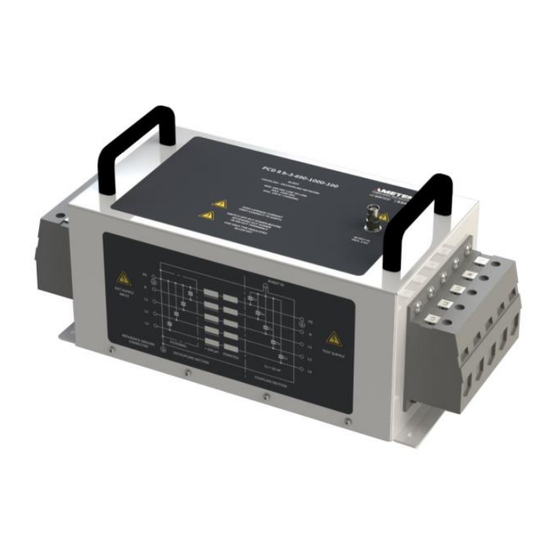
PCD 8 b-3-690-1000-100
- 8 kV Burst, 3 * 690 V AC, 1.000 V DC, 100 A
PCD 8 b-3-690-1000-200
- 8 kV Burst, 3 * 690 V AC, 1.000 V DC, 200 A
Testing of EFT/Burst up to 8 kV. The coupling PCD 8 b-series
coupling/decoupling network is manual operated by the user
and used to couple burst pulses high current AC and DC lines.
Version: 1.01 / 30.11.2020
Replaces: 1.00 / 25.11.2020
Filename: UserManual-PCD 8 b-series-E-V1.01.docx
Print date: 30.11.20
Burst as per
– IEC 61000-4-4
Advertisement
Table of Contents

Related Manuals for Ametek PCD 8 b Series


Summary of Contents for Ametek PCD 8 b Series
- Page 1 Manual f o r O p e r a t i n g PCD 8 b-series PCD 8 b-3-690-1000-100 - 8 kV Burst, 3 * 690 V AC, 1.000 V DC, 100 A PCD 8 b-3-690-1000-200 - 8 kV Burst, 3 * 690 V AC, 1.000 V DC, 200 A Burst as per –...
- Page 2 4153 Reinach BL1 Schweiz Phone : +41 61 204 41 11 Fax : +41 61 204 41 00 URL : http://www.ametek-cts.com Copyright © 2020 AMETEK CTS GmbH All right reserved. Specifications subject to change Operating Manual V 1.01 2 / 29...
-
Page 3: Table Of Contents
6.2. Calibration and Verification ......................... 24 6.2.1. Factory calibration ..........................24 6.2.2. Guideline to determine the calibration period of AMETEK CTS instrumentation ....... 24 6.2.3. Calibration of Accessories made by passive components only: ............24 6.2.4. Periodically In-house verification......................24 Delivery Groups ............................ - Page 4 AMETEK CTS PCD 8 b-series 8.1.2. Declaration of CE-Conformity coupling Network coupling PCD 8 b-3-690-1000-200 ......27 Operating Manual V 1.01 4 / 29...
-
Page 5: General
AMETEK CTS will, at its expense, deliver the repaired or replaced product or parts to the buyer. Any warranty of AMETEK CTS will not apply if the buyer is in default under the purchase order agreement or where the product or any part thereof: •... -
Page 6: Product Return Procedure
- Description of the problem NOTE: Unauthorized returns will not be accepted and will be returned at the shipper’s expense. NOTE: A returned product found upon inspection by AMETEK CTS, to be in specification is subject to an evaluation fee and applicable freight charges. -
Page 7: Safety Information
AMETEK CTS PCD 8 b-series Safety information Before using this equipment, read the operating manual and the separate delivered safety manual carefully Attention 2.1. Intended use The test system compact NX / NSG 30x0A with this PCD 8 b-series is designed primarily for conducted transient interference tests as specified in the European generic standards IEC/EN 61000-6-1 to cover equipment for household, office and light industrial use, and IEC/EN 61000-6-2 for applications in industrial environments. -
Page 8: Qualification Of Personnel
Neither AMETEK CTS nor any of the subsidiary sales organizations can accept any responsibility for personnel, material or inconsequential injury, loss or damage that results from improper use of the equipment and accessories. -
Page 9: Installation Put In Service
AMETEK CTS PCD 8 b-series Installation put in service This chapter includes a checklist with steps that should be taken before the PCD 8 b-series is switched on and put into operation. 3.1. Safety instructions for installation and initial installation National regulations in installation and operation of electrical equipment must be respected. -
Page 10: Installation Of The Pcd 8 B Coupling Network
Do not dispose of packaging materials. All packaging should be retained if the instrument or any of its accessories should need to be returned to an AMETEK CTS service center for repair or calibration. Using the following list, check that all the items ordered have been delivered (see also chapter 7.1):... -
Page 11: Grounding
AMETEK CTS PCD 8 b-series 3.2.2. Grounding The instruments conform to the safety requirements, but with an increased leakage current given by the decoupling filter. Operate the equipment only in dry and clean surroundings. Any condensation that occurs must be allowed to evaporate before putting the equipment into operation. Do not exceed the permissible ambient temperature or humidity given in the IEC specification. -
Page 12: Power Connection, 3-Phase Ac
AMETEK CTS PCD 8 b-series 3.2.4. Power connection, 3-phase AC Figure 3.2: Connection with 3-phase AC main supply 3.2.5. Power connection, DC Figure 3.3: Connection with DC supply 3.2.6. EUT power supply The power is fed in via a 5-core cable usually brought out as: *Note: For 1-phase or DC application it is possible to use the input channels in parallel, thus it is possible to increase the max. -
Page 13: Setup
AMETEK CTS PCD 8 b-series The earth connection lug on the power supply input serves to ensure a good connection to the protective earth on the coupling network. Every test rig must be planned carefully. All the instrumentation should be readily accessible and rigidly positioned. -
Page 14: Firmware Settings
AMETEK CTS PCD 8 b-series 3.3. Firmware settings 3.3.1. Activate of the PCD 8 b in compact NX Select from Main Menu, then press SETUP: Select EXTERNAL COUPLERS in the EQUIPMENTS section. If the PCD 8 b is not yet in the list, it can be added by pressing + ADD. -
Page 15: Selecting The Pcd 8 B In Test-Mode (Compact Nx)
AMETEK CTS PCD 8 b-series Then select your PCD from the list. If you are using both the 100 and 200 A version, please ensure that both PCDs are selected (one after the other). 3.3.2. Selecting the PCD 8 b in test-mode (compact NX) To be able to select the PCD 8 b for coupling, it must first be activated as an external coupler as shown in chapter 3.3.1. -
Page 16: Activate Of The Pcd 8 B In Nsg 3000A
AMETEK CTS PCD 8 b-series 3.3.3. Activate of the PCD 8 b in NSG 3000A Select from Main Menu, then press SETUP: Select EXTERNAL COUPLERS in the EQUIPMENTS section. If the PCD 8 b is not yet in the list, it can be added by pressing + ADD. -
Page 17: Selecting The Pcd 8 B In Test-Mode (Nsg 3000A)
AMETEK CTS PCD 8 b-series Open the selection menu and select CDN. Then select your PCD from the list. If you are using both the 100 and 200 A version, please ensure that both PCDs are selected (one after the other). -
Page 18: List Of Coupling Networks
AMETEK CTS PCD 8 b-series List of coupling networks Coupling network for Burst impulses: Device Impulse voltage Phases EUT Voltage [V] EUT Current [A] PCD 8 b-3-690-1000-100 8 kV +, -, PE 690 AC, 1000 DC PCD 8 b-3-690-1000-200 8 kV... -
Page 19: General
AMETEK CTS PCD 8 b-series PCD 8 b-3-690-1000-100/200 5.1. General The manual coupling decoupling networks PCD 8 b-3-690-1000-100 and PCD 8 b-3-690-1000-200 are designed for EFT / Burst testing to high voltage and current AC/DC supply lines up to 3 * 690 V AC, 1000 V DC and 100 / 200 A. -
Page 20: Front View Pcd 8 B-3-690-1000-100
AMETEK CTS PCD 8 b-series 5.2. Front view PCD 8 b-3-690-1000-100 Figure 5.2: Front view coupling PCD 8 b-3-690-1000-100 Power supply input EFT / Burst input from Generator Power supply output to EUT Block diagram Power supply input Input screw terminal L1(DC+), L2, L3, N(DC-), and PE. Max. voltage 3 * 690 V AC, 1000 V DC, 100 A. -
Page 21: Front View Pcd 8 B-3-690-1000-200
AMETEK CTS PCD 8 b-series 5.3. Front view PCD 8 b-3-690-1000-200 Figure 5.3: Front view coupling PCD 8 b-3-690-1000-200 Power supply input EFT / Burst input from Generator Power supply output to EUT Block diagram Power supply input Input screw terminal L1(DC+), L2, L3, N(DC-), and PE. Max. voltage 3 * 690 V AC, 1000 V DC, 200 A. -
Page 22: Technical Data Pcd 8 B-3-690-1000-100/200
AMETEK CTS PCD 8 b-series 5.4. Technical data PCD 8 b-3-690-1000-100/200 General data PCD 8 b-3-690-1000-100 Parameter Value Impulse voltage Burst max. 8.0 kV Coupling mode Common mode, simultaneously to L1(DC+), L2, L3, N(DC-), and PE Coupling capacitor 33 nF Residual voltage <... -
Page 23: Block Diagram Pcd 8 B-3-690-1000-100/200
AMETEK CTS PCD 8 b-series 5.5. Block diagram PCD 8 b-3-690-1000-100/200 Figure 5.4: Block diagram PCD 8 b-3-690-1000-100/200 Operating Manual V 1.01 23 / 29... -
Page 24: Maintenance And Calibration
AMETEK CTS equipment. AMETEK CTS does not know each customer’s Quality Assurance Policy, nor do we know how often the equipment is used and what kind of tests is performed during the life cycle of test equipment. Only the customer knows all the details and therefore the customer needs to specify the calibration interval for his test equipment. -
Page 25: Delivery Groups
AMETEK CTS PCD 8 b-series Delivery Groups 7.1. Basic equipment PCD 8 b-3-690-1000-100 PCD 8 b-3-690-1000-100 Safety manual (only one per delivery) User manual (pdf on the delivered memory stick) 1 BCC 1000 SHV, coaxial connection cable, 1.0 m, both sides SHV connector... -
Page 26: Appendix
AMETEK CTS GmbH Sternenhofstr. 15 CH 4153 Reinach Phone: +41 61 204 41 11 Fax: +41 61 204 41 00 A. Burger Director Engineering AMETEK CTS Place Reinach BL, Switzerland Date 01. November 2020 Operating Manual V 1.01 26 / 29... - Page 27 AMETEK CTS GmbH Sternenhofstr. 15 CH 4153 Reinach Phone: +41 61 204 41 11 Fax: +41 61 204 41 00 A. Burger Director Engineering AMETEK CTS Place Reinach BL, Switzerland Date 01. November 2020 Operating Manual V 1.01 27 / 29...
- Page 29 AMETEK CTS PCD 8 b-series Manual of operation V 1.01 29 / 29...
Need help?
Do you have a question about the PCD 8 b Series and is the answer not in the manual?
Questions and answers