Table of Contents
Advertisement
Quick Links
Manual
f o r
O p e r a t i n g
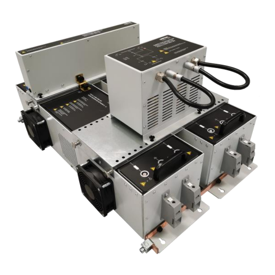
PCD 8 s-series
PCD 8 s-3-690-1000-100
- 8 kV Surge, 3 * 690 V AC, 1.000 V DC, 100 A
PCD 8 s-3-690-1000-200
- 8 kV Surge, 3 * 690 V AC, 1.000 V DC, 200 A
Testing of Surge up to 8 kV. The coupling PCD 8 s-series
coupling/decoupling network is manual operated by the user
and used to couple burst pulses high current AC and DC lines.
Version: 2.02 / 26.08.2022
Replaces: 2.01 / 25.08.2022
Filename: UserManual-PCD 8 s-series-E-V2.02.docx
Print date: 26.08.22
Surge as per
– IEC 61000-4-5
Advertisement
Table of Contents

Related Manuals for Ametek PCD 8 S Series


Summary of Contents for Ametek PCD 8 S Series
- Page 1 Manual f o r O p e r a t i n g PCD 8 s-series PCD 8 s-3-690-1000-100 - 8 kV Surge, 3 * 690 V AC, 1.000 V DC, 100 A PCD 8 s-3-690-1000-200 - 8 kV Surge, 3 * 690 V AC, 1.000 V DC, 200 A Testing of Surge up to 8 kV.
- Page 2 4153 Reinach BL1 Schweiz Phone : +41 61 204 41 11 Fax : +41 61 204 41 00 URL : http://www.ametek-cts.com Copyright © 2022 AMETEK CTS GmbH All right reserved. Specifications subject to change Operating Manual V 2.02 2 / 53...
-
Page 3: Table Of Contents
6.2. Calibration and Verification ......................... 29 6.2.1. Factory calibration ..........................29 6.2.2. Guideline to determine the calibration period of AMETEK CTS instrumentation ....... 29 6.2.3. Calibration of Accessories made by passive components only: ............29 6.2.4. Periodically In-house verification......................29 Delivery Groups ............................ - Page 4 AMETEK CTS PCD 8 s-series 8.2. IEC line to ground ..........................34 8.3. Optional IEC coupling (only with second SCB) ................... 35 8.4. ANSI coupling modes (only with second SCB) ................... 36 Coupling guide ............................38 9.1. IEC coupling Line to Ground (9 µF) ....................38 9.2.
-
Page 5: General
AMETEK CTS will, at its expense, deliver the repaired or replaced product or parts to the buyer. Any warranty of AMETEK CTS will not apply if the buyer is in default under the purchase order agreement or where the product or any part thereof: •... -
Page 6: Product Return Procedure
- Description of the problem NOTE: Unauthorized returns will not be accepted and will be returned at the shipper’s expense. NOTE: A returned product found upon inspection by AMETEK CTS, to be in specification is subject to an evaluation fee and applicable freight charges. -
Page 7: Safety Information
AMETEK CTS PCD 8 s-series Safety information Before using this equipment, read the operating manual and the separate delivered safety manual carefully Attention 2.1. Intended use The test system compact NX / NSG 30x0A with this PCD 8 s-series is designed primarily for conducted transient interference tests as specified in the European generic standards IEC/EN 61000-6-1 to cover equipment for household, office and light industrial use, and IEC/EN 61000-6-2 for applications in industrial environments. -
Page 8: Qualification Of Personnel
Neither AMETEK CTS nor any of the subsidiary sales organizations can accept any responsibility for personnel, material or inconsequential injury, loss or damage that results from improper use of the equipment and accessories. -
Page 9: Installation Put In Service
AMETEK CTS PCD 8 s-series Installation put in service This chapter includes a checklist with steps that should be taken before the PCD 8 s-series is switched on and put into operation. 3.1. Safety instructions for installation and initial installation National regulations in installation and operation of electrical equipment must be respected. -
Page 10: Installation Of The Pcd 8 S Coupling Network
Do not dispose of packaging materials. All packaging should be retained if the instrument or any of its accessories should need to be returned to an AMETEK CTS service center for repair or calibration. Using the following list, check that all the items ordered have been delivered (see also chapter 7.1): PCD 8 s-3-690-1000-100 PCD 8 s-3-690-1000-100 incl. -
Page 11: Assembling Of The Pcd 8 S-3-690-1000-100/-200
AMETEK CTS PCD 8 s-series 3.2.3. Assembling of the PCD 8 s-3-690-1000-100/-200 Prepare the test setup conform to the chosen standard and put both decoupling network units, etc. to the place where the CDN shall be used for testing. Mounting of the common earth rails Place the two surge decoupling networks in parallel to each other. - Page 12 AMETEK CTS PCD 8 s-series Mounting positioning plates Screw the base plates (positioning plates) of the sync unit and of the coupling unit, with the knurled screws to the foreseen holes on the outside of the decoupling networks. If PCD 8 s decoupling networks are not placed correctly, the positioning plates cannot be screwed on.
- Page 13 AMETEK CTS PCD 8 s-series Assembly for IEC coupling For IEC coupling, add the coupling module SCB in the middle of the big positioning plate and press it slightly down into the positioning holes. Fix the SCB by pushing the 4 black quick snap-on knobs down (A). Connect the ground terminal of the SCB to the decoupling network (B).
-
Page 14: Grounding
AMETEK CTS PCD 8 s-series Assembly for ANSI coupling or additional IEC lines coupling mode For ANSI coupling or additional IEC lines coupling add 2 coupling modules SCB on the big positioning plate and press them slightly down into the positioning holes. Fix the SCB’s by pushing the black quick snap-on knobs down (A). - Page 15 AMETEK CTS PCD 8 s-series It is recommended to connect the PCD 8 s through a properly rated power switch device, which should be located close to the test setup. To ensure an easy and quick access to the EUT power, the switch should be clearly and visibly labelled as a device for «EUT power on/off»...
-
Page 16: Power Connection, 1-Phase Ac
AMETEK CTS PCD 8 s-series 3.2.5. Power connection, 1-phase AC NOTE The PCD 8 s is equipped with EUT terminals suitable for a max. wire gauge of 110 mm2 AWG 4-4/0 (230 A), torque: max. 20 Nm. Figure 3.1: Connection with 1-phase AC mains supply 3.2.6. -
Page 17: Power Connection, Dc
AMETEK CTS PCD 8 s-series 3.2.7. Power connection, DC Figure 3.3: Connection with DC supply 3.2.8. EUT power supply The power is fed in via a 5-core cable usually brought out as: NOTE Care must be taken for 1-phase or DC application to prevent the risk of electrical shock through unused channels (screwed connectors). -
Page 18: Firmware Settings
AMETEK CTS PCD 8 s-series 3.3. Firmware settings 3.3.1. Activate of the PCD 8 s in compact NX Select from Main Menu, then press SETUP: Select EXTERNAL COUPLERS in the EQUIPMENTS section. If the PCD 8 s is not yet in the list, it can be added by pressing + ADD. -
Page 19: Selecting The Pcd 8 S In Test-Mode (Compact Nx)
AMETEK CTS PCD 8 s-series Then select your PCD from the list. If you are using both the 100 and 200 A version, please ensure that both PCDs are selected (one after the other). 3.3.2. Selecting the PCD 8 s in test-mode (compact NX) To be able to select the PCD 8 s for coupling, it must first be activated as an external coupler as shown in chapter 3.3.1. -
Page 20: Activate Of The Pcd 8 S In Nsg 3000A
AMETEK CTS PCD 8 s-series 3.3.3. Activate of the PCD 8 s in NSG 3000A Select from Main Menu, then press SETUP: Select EXTERNAL COUPLERS in the EQUIPMENTS section. If the PCD 8 s is not yet in the list, it can be added by pressing + ADD. -
Page 21: Selecting The Pcd 8 S In Test-Mode (Nsg 3000A)
AMETEK CTS PCD 8 s-series Open the selection menu and select CDN. Then select your PCD from the list. If you are using both the 100 and 200 A version, please ensure that both PCDs are selected (one after the other). -
Page 22: List Of Coupling Networks
AMETEK CTS PCD 8 s-series List of coupling networks Coupling network for Surge impulses: Device Impulse voltage Phases EUT Voltage [V] EUT Current [A] PCD 8 s-3-690-1000-100 8 kV +, -, PE 690 AC, 1000 DC PCD 8 s-3-690-1000-200 8 kV... -
Page 23: Input Pcd 8 S-3-690-1000-100/200
AMETEK CTS PCD 8 s-series PCD 8 s-3-690-1000-100/200 5.1. Input PCD 8 s-3-690-1000-100/200 Figure 5.2: Input coupling PCD 8 s-3-690-1000-200 Power supply input L3-L2 Decoupling network L1-N Earth rail (PE) Decoupling network L3-L2 Surge generator synch. input Sync unit Jumper for capacitance setting (Jc) - Page 24 AMETEK CTS PCD 8 s-series Power supply input L3-L2 Input screw terminal L3 and L2. Max. voltage 3 * 690 V AC, 1.000 V DC Earth rail (PE) Screw terminal for protected earth (PE). Surge generator synch. input Needs to be connected to the synch connection of the generator (also see 3) 10 Jumper for capacitance setting (Jc) The jumper is used to set the coupling capacitance to 9 or 18 µF, please follow the instructions in the Coupling...
-
Page 25: Output Pcd 8 S-3-690-1000-100/200
AMETEK CTS PCD 8 s-series 5.2. Output PCD 8 s-3-690-1000-100/200 Figure 5.2: Output coupling PCD 8 s-3-690-1000-200 Surge input coupling network EUT test supply L1-N / DC+-DC- EUT test supply L3-L2 Earth rail (PE) Surge output SCB EUT test supply L1-N / DC+-DC-... -
Page 26: Pcd 8 S-3-690-1000 Scb (Input)
AMETEK CTS PCD 8 s-series 5.3. PCD 8 s-3-690-1000 SCB (Input) Figure 5.3: Surge Coupling Box SCB (Input) Earth connection (PE) Jumper for capacitance setting Input from Surge generator (high) Jumper for impedance setting Jumper for capacitance setting (Jc) SWx open circuit -> Cx 9 µF SWx short circuit ->... -
Page 27: Pcd 8 S-3-690-1000 Scb (Overview / Output)
AMETEK CTS PCD 8 s-series 5.4. PCD 8 s-3-690-1000 SCB (Overview / Output) Figure 5.4: Surge Coupling Box SCB (Overview / Output) Coupling capacitor C1 Jumper for capacitance setting Output C1 Jumper for impedance setting Coupling capacitor C2 Explanation capacitance... -
Page 28: Technical Data Pcd 8 S-3-690-1000-100/200
AMETEK CTS PCD 8 s-series 5.5. Technical data PCD 8 s-3-690-1000-100/200 General data PCD 8 s-3-690-1000-100 Parameter Value Impulse voltage Surge max. 8.0 kV Coupling mode Lx - Lx and Lx - PE with 1 SCB (Surge Coupling Box) included in delivery Decoupling inductance 0.3 mH +/- 10 %... -
Page 29: Maintenance And Calibration
AMETEK CTS equipment. AMETEK CTS does not know each customer’s Quality Assurance Policy, nor do we know how often the equipment is used and what kind of tests is performed during the life cycle of test equipment. Only the customer knows all the details and therefore the customer needs to specify the calibration interval for his test equipment. -
Page 30: Delivery Groups
AMETEK CTS PCD 8 s-series Delivery Groups 7.1. Basic equipment PCD 8 s-3-690-1000-100 Item Name Remark Picture PCD 8 s-3-690-1000- Manual Surge coupling network (100 A) - without fan motors - incl. 1 pcs. Surge coupling box for IEC coupling L-L and L-PE. - Page 31 AMETEK CTS PCD 8 s-series PCD 8 s-3-690-1000-200 PCD 8 s-3-690-1000- Manual Surge coupling network (200 A) - incl. 4 fan motors - incl. 1 pcs. Surge coupling box for IEC coupling L-L and L-PE. IAK 6 Isolated Allen key for screw terminal, 6 mm...
-
Page 32: Accessories And Options
AMETEK CTS PCD 8 s-series Check the equipment for signs of transport damage. Any damage should be reported to the Transportation Company and local representative immediately. 7.2. Accessories and options PCD 8 s-3-690-1000 SCB (#1006198) Additional Surge Coupling Unit (SCB); Enables ANSI and optional IEC coupling (in combination with the SCB included in delivery). -
Page 33: Coupling Mode Overview
AMETEK CTS PCD 8 s-series Coupling mode overview All IEC 61000-4-5 coupling possibilities are listed below. For easy understanding, the Surge Coupling Box (SCB) input is identified by X1 while the outputs are marked with X2 and X3. The jumper for impedance adjustment is marked Ji. -
Page 34: Iec Line To Line
AMETEK CTS PCD 8 s-series 8.1. IEC line to line Line to line (18 µF) L1 - N L1 - L2 L1 - L3 L2 - N L2 - L1 L2 - L3 L3 - N L3 - L1 L3 - L2... -
Page 35: Optional Iec Coupling (Only With Second Scb)
AMETEK CTS PCD 8 s-series 8.3. Optional IEC coupling (only with second SCB) Optional coupling modes are possible with a second Surge Coupling Box (SCB). Those are different multiline couplings to ground such as: Lines to ground (9 µF) L1+L2 - PE... -
Page 36: Ansi Coupling Modes (Only With Second Scb)
AMETEK CTS PCD 8 s-series 8.4. ANSI coupling modes (only with second SCB) For coupling modes required by ANSI standard, a second SCB needs to be added on the PCD 8 s. Basic 1 L1+L2+L3+N - PE Basic 2 L2 - L1... - Page 37 AMETEK CTS PCD 8 s-series Operating Manual V 2.02 37 / 53...
-
Page 38: Coupling Guide
AMETEK CTS PCD 8 s-series Coupling guide 9.1. IEC coupling Line to Ground (9 µF) Operating Manual V 2.02 38 / 53... -
Page 39: Iec Coupling Line To Line (18 Μf)
AMETEK CTS PCD 8 s-series 9.2. IEC coupling Line to Line (18 µF) Operating Manual V 2.02 39 / 53... -
Page 40: Optional Iec Coupling Lines To Ground (9 Μf), 1/3
AMETEK CTS PCD 8 s-series 9.3. Optional IEC coupling Lines to Ground (9 µF), 1/3 Operating Manual V 2.02 40 / 53... -
Page 41: Optional Iec Coupling Lines To Ground (9 Μf), 2/3
AMETEK CTS PCD 8 s-series 9.4. Optional IEC coupling Lines to Ground (9 µF), 2/3 Operating Manual V 2.02 41 / 53... -
Page 42: Optional Iec Coupling Lines To Ground (9 Μf), 3/3
AMETEK CTS PCD 8 s-series 9.5. Optional IEC coupling Lines to Ground (9 µF), 3/3 Operating Manual V 2.02 42 / 53... -
Page 43: Optional Ansi Coupling, 1/5 (Basic)
AMETEK CTS PCD 8 s-series 9.6. Optional ANSI coupling, 1/5 (Basic) Operating Manual V 2.02 43 / 53... -
Page 44: Optional Ansi Coupling, 2/5 (Basic)
AMETEK CTS PCD 8 s-series 9.7. Optional ANSI coupling, 2/5 (Basic) Operating Manual V 2.02 44 / 53... -
Page 45: Optional Ansi Coupling, 3/5 (Supplemental)
AMETEK CTS PCD 8 s-series 9.8. Optional ANSI coupling, 3/5 (Supplemental) Operating Manual V 2.02 45 / 53... -
Page 46: Optional Ansi Coupling, 4/5 (Supplemental)
AMETEK CTS PCD 8 s-series 9.9. Optional ANSI coupling, 4/5 (Supplemental) Operating Manual V 2.02 46 / 53... -
Page 47: Optional Ansi Coupling, 5/5 (Diagnostic)
AMETEK CTS PCD 8 s-series 9.10. Optional ANSI coupling, 5/5 (Diagnostic) Operating Manual V 2.02 47 / 53... -
Page 48: Effects On The Eut
AMETEK CTS PCD 8 s-series Effects on the EUT The surge pulse contains considerable energy. When super-imposed on the mains, a significant resultant current can occur if the EUT becomes defective. The effects can be very different, depending on the characteristics of the equipment undergoing the test: •... -
Page 49: Aspects Of Calibration And Setup
AMETEK CTS PCD 8 s-series spects of calibration and setup 11.1. Calibration setup acc. ANSI The ANSI standard specify following conditions for verification/calibration: The surge generator is connected to the back filter via the coupling network in the relevant coupling mode. -
Page 50: Appendix
AMETEK CTS GmbH Sternenhofstr. 15 CH 4153 Reinach Phone: +41 61 204 41 11 Fax: +41 61 204 41 00 A. Burger Director Engineering AMETEK CTS Place Reinach BL, Switzerland Date 01. November 2020 Operating Manual V 2.02 50 / 53... -
Page 51: Declaration Of Ce-Conformity Coupling Network Coupling Pcd 8 S-3-690-1000-200
AMETEK CTS GmbH Sternenhofstr. 15 CH 4153 Reinach Phone: +41 61 204 41 11 Fax: +41 61 204 41 00 A. Burger Director Engineering AMETEK CTS Place Reinach BL, Switzerland Date 01. November 2020 Operating Manual V 2.02 51 / 53... - Page 53 AMETEK CTS PCD 8 s-series Manual of operation V 1.00 53 / 53...
Need help?
Do you have a question about the PCD 8 S Series and is the answer not in the manual?
Questions and answers