Advertisement
Quick Links
HOLDING TANK MONITOR
SENDER MANUAL
710-AR
CANADA
USA
Garnet Instruments Ltd.
Garnet US Inc.
286 Kaska Road
5360 Old Granbury Road
Sherwood Park, AB T8A 4G7
Granbury, TX 76049
SeeLeveL Sender Installation Manual 710-AR / 710-ES2
|
710-ES2
INTRODUCTION
The SeeLeveL Senders are used with SeeLeveL Tank Monitoring systems
that can monitor up to seven tanks and now has more efficient power
consumption. The senders are mounted on the outside of the holding
tanks and can be stacked to fit taller tanks. Depending on tank height and
desired resolution, Garnet offers two different sender options. They are
not compatible with metal holding tanks. They work on most plastic or
polyethylene holding tanks that contain water-soluble fluids.
The 710-AR is our standard sender. This model is 9" high (not including
tabs) and can measure tanks from as short as 3.5" up to as high as 10.5"
using a single sender, and up to 19.5" with double-stacked senders and
will accommodate the majority of holding tanks. The higher resolution is
1/4" which is optimal for low-profile tanks.
The 710-ES2 sender is an enhanced version of the 710-ES. This model is
12" high (not including tabs) with a resolution of 3/8" and can measure
tanks from 5.5" up to 14" as a single, and up to 26" with double-stacked.
See more information about sender lengths on page 3.
The communication protocol used between our senders and displays is
proprietary allowing us to control the accuracy and functionality of our
systems ensuring our customers experience reliable operation.
SAFETY SYMBOLS INFORMATION
NOTE: expands on information for any procedures.
W
CAUTION: explains safety information that could cause
W
damage to the product, including data loss.
WARNING: explains dangers that might result in
W
personal injury or death.
Changes or modifications not expressly approved by the
party responsible for compliance could void the user's
authority to operate the equipment.
710-AR-ES2 Manual_v1.2 - 25-Oct-2023
Page 1
Advertisement

Related Manuals for Garnet SeeLevel 710-ES2


Summary of Contents for Garnet SeeLevel 710-ES2
- Page 1 HOLDING TANK MONITOR tanks and can be stacked to fit taller tanks. Depending on tank height and desired resolution, Garnet offers two different sender options. They are not compatible with metal holding tanks. They work on most plastic or polyethylene holding tanks that contain water-soluble fluids.
-
Page 2: Installation Information
This manual provides information on how to install the SeeLeveL 710-AR and 710-ES2 senders. Make sure that any metal is at least 1” away from either side, top and bottom of the sender, and at least 2”... -
Page 3: Single Configuration
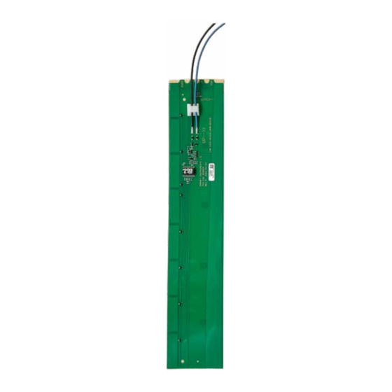
DETERMINE MEASURABLE SPACE ON TANKS Find Measurable Space Single configuration Measure the height of the tank from top to bottom then determine measurable space. 1. Measure the height of the tank. • The minimum gap is 1/4", however, we recommend that the senders be installed 1/2"... - Page 4 SENDER SPECIFICATIONS 710-AR Sender 710-ES2 Sender Black ground wire 2.45" Blue signal wire Black ground wire Blue 2.45" signal wire Continuous Continuous Segmented pads Segmented (1.5" long) pads (1" long) 12" 9" SeeLeveL Sender Installation Manual 710-AR / 710-ES2 Page 4...
- Page 5 CUTTING SENDERS PROGRAMMING THE SENDERS TABS The senders need to be cut to the required length to match the height of the measurable space of the tank. 2/GRY 3/BLK The cut must be between the sender segmented pads. Senders have a minimum length they can be cut.
- Page 6 PROGRAMMING THE SENDERS Tabs to cut for single sender or bottom sender if double-stacked. NOTE: Previous model senders 2/GRY 3/BLK 2/GRY (710-ES, 710-JS, 710-SS) can be combined with new sender models. NOTE: For systems that have a Galley button. Cut the 2/GRY and the TOP tabs.
- Page 7 PREPARE SENDER FOR INSTALLATION ❶ ❷ Clean the tank Temporarily tape sender on tank Clean area thoroughly where the sender will be CAUTION: DO NOT SKIP THE FOLLOWING STEPS. Removing the sender mounted making sure there is no dust, grease from the tank after the sender has been permanently installed will cause damage and oil.
- Page 8 WIRING THE SENDER ❸ Connect the wiring to the pigtail The following diagram shows the wiring from the sender to the pigtail. Other wiring connections may apply for each model. All wiring diagrams are available on the website. PIGTAIL HARNESS TO PUMP INDICATOR +12V POWER...
- Page 9 SENDER TEST ❹ Verify operation before permanently adhering the sender to the tank. Tank levels operation test For the initial test, have the tank at least 1/4 full of water or sewage. Verify that the percent level reading on the display panel looks correct.
- Page 10 MOUNTING THE SENDER ❻ Secure the wires ❺ Permanently adhere sender to the tank Secure the wires with duct tape, tie wraps, or something similar so that the wires do not rattle or Once proper operation has been confirmed, the press against the sender, this may result in sender sender will be ready to be permanently installed damage or wires breaking over time.
Need help?
Do you have a question about the SeeLevel 710-ES2 and is the answer not in the manual?
Questions and answers