Table of Contents
Advertisement
---
--------------------
RADIO
RADIO
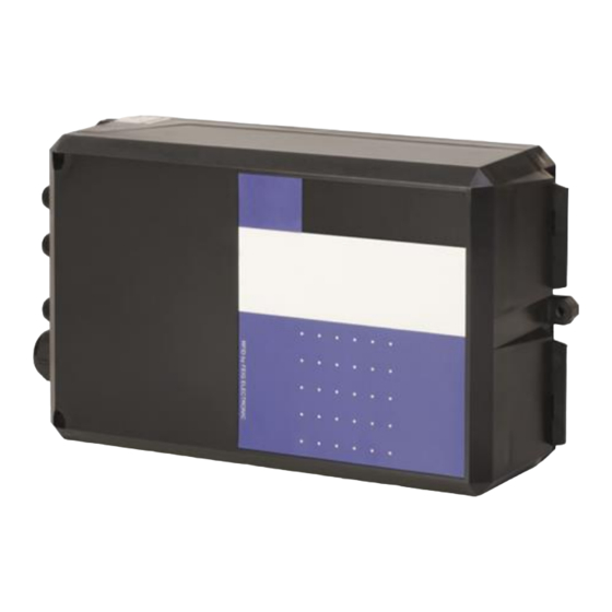
EUT: ID LRM5400
TÜV NORD Hochfrequenztechnik GmbH & Co. KG
LESKANPARK, Building 10, Waltherstr. 49-51, 51069 Cologne, Germany
--------------------
RADIO
FCC ID: PJMLRM5400
Annex acc. to FCC Title 47 CFR Part 15
FEIG ELECTRONIC GmbH
Annex no. 4
User Manual
Functional Description
Title 47 - Telecommunication
Part 15 - Radio Frequency Devices
Subpart C – Intentional Radiators
Measurement Procedure:
ANSI C63.4-2014
ANSI C63.10-2013
Page 1 of 32
--------------------
--------------------
RADIO
FCC Title 47 CFR Part 15
relating to
ID LRM5400
Test report no. 23012728_Rev. 00
--------------------
RADIO
Date of issue: 2023-03-09
Tel.: +49 221 8888950
hf@tuev-nord.de
RADIO
V1.23
Advertisement
Table of Contents

Related Manuals for Feig Electronic ID LR5400


Summary of Contents for Feig Electronic ID LR5400
- Page 1 FCC ID: PJMLRM5400 FCC Title 47 CFR Part 15 Date of issue: 2023-03-09 Annex acc. to FCC Title 47 CFR Part 15 relating to FEIG ELECTRONIC GmbH ID LRM5400 Annex no. 4 User Manual Functional Description Title 47 - Telecommunication Part 15 - Radio Frequency Devices Subpart C –...
- Page 2 Page 2 of 32 Test report no. 23012728_Rev. 00 -------------------- -------------------- -------------------- -------------------- -------------------- RADIO RADIO RADIO RADIO RADIO RADIO EUT: ID LRM5400 FCC ID: PJMLRM5400 FCC Title 47 CFR Part 15 Date of issue: 2023-03-09 User manual/ Functional description of the test equipment (EUT) V1.23 TÜV NORD Hochfrequenztechnik GmbH &...
- Page 3 IDENTIFICATION Installation ID LR5400 ID LRM5400 Long Range Reader ID LR5400 (Housing) ID LRM5400 (Modul) M21023-0e-ID-B...
- Page 4 FEIG ELECTRONIC GmbH calls explicit attention that devices which are subject of this document are not designed with components and testing methods for a level of reliability suitable for use in or in connection with surgical implants or as critical components in any life support systems whose failure to perform can reasonably be expected to cause significant injury to human health.
- Page 5 IDENTIFICATION ID LR(M)5400 Safety Instructions Safety Instructions ► The device may only be used for the intended purpose designed by for the manufacturer. ► The operation manual should be conveniently kept available at all times for each user. ► Unauthorized changes and the use of spare parts and additional devices which have not been sold or recommended by the manufacturer may cause fire, electric shocks or injuries.
- Page 6 IDENTIFICATION ID LR(M)5400 History of Documentation History of Documentation Revision Date Description 0e (english) October 2022 Initial Version Installation Page 4 of 30...
-
Page 7: Table Of Contents
Available Reader Type ...................... 7 Installation and mounting Installation ......................... 8 Control elements and connection terminals..............11 2.2.1 Cable Glands (only ID LR5400 housing) .............. 12 2.2.2 Open the cover ..................... 13 Antenna connections ...................... 14 Power supply ........................15 Digital Inputs IN1, IN2, IN3 .................... - Page 8 IDENTIFICATION ID LR(M)5400 Content Technical Data Installation Page 6 of 30...
-
Page 9: Performance Features
Performance Features 1 Performance Features The ID LR5400 is a reader for contactless data exchange with transponders according to ISO 15693 and ISO 18000-3M3 (smart labels). It is designed for use with one or more external antennas. The connection to a computer or other device (host) is made via one of the three interfaces. -
Page 10: Installation And Mounting
IDENTIFICATION ID LR(M)5400 Installation and mounting 2 Installation and mounting 2.1 Installation The reader module is designed for mounting on a heat sink. For mounting, there are five holes each with Ø 4.5 mm (marked yellow) in the carrier plate. Housing Figure 2: Side view housing Figure 1: Top view housing... - Page 11 IDENTIFICATION ID LR(M)5400 Installation and mounting Figure 3: Front view readermodul Figure 4: Top view readermodul with bolt holes Installation Page 9 of 30...
- Page 12 IDENTIFICATION ID LR(M)5400 Installation and mounting The following points must be observed to utilize the full performance of the reader module: • The thermal resistance RThK of the heat sink must not exceed a maximum of 1.0 K/W. ≤ 1,0 K/W •...
-
Page 13: Control Elements And Connection Terminals
IDENTIFICATION ID LR(M)5400 Installation and mounting 2.2 Control elements and connection terminals X1 – X6 Terminals V1 - V6 Jumper J1 - J15 Antenna terminals ANT1- ANT4 Figure 5: Marked terminals, jumper and LEDs Figure 6: Antenna terminals ANT1-ANT4 Installation Page 11 of 30... -
Page 14: Cable Glands (Only Id Lr5400 Housing)
IDENTIFICATION ID LR(M)5400 Installation and mounting 2.2.1 Cable Glands (only ID LR5400 housing) The cable glands are located on the underside of the housing. Figure 7: Cable glands on the underside of the housing Cable gland Size Clamping range [mm]... -
Page 15: Open The Cover
IDENTIFICATION ID LR(M)5400 Installation and mounting Cable routing Figure 8: Arrangement of the connecting cables 2.2.2 Open the cover The latch on the housing cover must be pressed outward with a screwdriver. Figure 9: Open the cover Installation Page 13 of 30... -
Page 16: Antenna Connections
FEIG ELECTRONIC GmbH and for all antennas which are equipped with the adjustment boards (e.g. ID DAT, ID MAT-B and ID MAT-S) from FEIG ELECTRONIC GmbH the optimum length of the coaxial cable is 1.35 m (article no. 1654.004.00.00, designation ID ANT.C-B). -
Page 17: Power Supply
IDENTIFICATION ID LR(M)5400 Installation and mounting 2.4 Power supply The reader must be powered only from a power source conforming to EN 62368-1 Chapter Q.1 Power Sources of Limited Capacity or with an NEC Class 2/LPS certified power supply. The external circuitry of the power supply: ≥ 0.5 mm The supply voltage of 24 VDC is connected to Terminal X6. -
Page 18: Digital Inputs In1, In2, In3
IDENTIFICATION ID LR(M)5400 Installation and mounting 2.5 Digital Inputs IN1, IN2, IN3 The three digital inputs are available on terminal X2. The digital inputs on terminal strips X2 are galvanically isolated from the reader electronics and must therefore be powered externally. The external VDC voltage may however be provided by the reader The 3 inputs are individually configurable. - Page 19 IDENTIFICATION ID LR(M)5400 Installation and mounting Jumper settings power supply Digit. Eingänge Jumper Beschreibung IN1 (X2) Bypassing the series resistor at VDC < 10 V IN2 (X2) Bypassing the series resistor at VDC < 10 V IN3 (X2) Bypassing the series resistor at VDC < 10 V Table 4: Jumper for inputs IN1, IN2 und IN3 Setting internal or external power supply Power supply...
-
Page 20: Digital Outputs Out1, Out2
IDENTIFICATION ID LR(M)5400 Installation and mounting Digital outputs OUT1, OUT2 The digital outputs on terminal strips X2 are galvanically isolated from the reader electronics and must therefore be powered externally and are carried to the outside without any internal ancillary circuitry on terminal X2. -
Page 21: Relay Rel1, Rel2
IDENTIFICATION ID LR(M)5400 Installation and mounting Relay REL1, REL2 The relay outputs are all a normally open contact. These outputs, which are located on terminals X2, are galvanically isolated from the Reader electronics and must therefore be externally supplied. The external voltage may however be provided by the card using jumper J7;J8;J9. -
Page 22: Power Supply 24 Vdc/Gnd
IDENTIFICATION ID LR(M)5400 Installation and mounting 2.8 Power supply 24 VDC/GND The output 24V/GND on X2 can be used to power the optional external circuitry of the digital inputs, outputs or relays. The maximum current consumption must not exceed 500 mA. A possible current consumption via J2, J4, J6 or J7, J8, J9 must be factored in. -
Page 23: Rs485-Interface X3 (Peripherie Device / Feig Specific)
IDENTIFICATION ID LR(M)5400 Installation and mounting Jumper closed open Pull-Down on RS4xx - A without Pull-Down on RS4xx - A Pull-Up on RS4xx - B without Pull-Up on RS4xx - B Termination resistor active Table 9: Jumper RS485 interface NOTE: The termination resristor can be added with Jumper J15. -
Page 24: Usb Interface X4 (Host Communication, Hid)
IDENTIFICATION ID LR(M)5400 Installation and mounting Bild 2: Jumper RS485-Peripherie-Device Interface 2.9.1.1 Address assignment of RS485 for bus operation For bus operation the Reader can be assigned the required bus address via software. The address is assigned by the host computer. The software is used to assign addresses “0” through “254” to the Reader. -
Page 25: Usb-Host Interface X5
IDENTIFICATION ID LR(M)5400 Installation and mounting 2.9.3 USB-Host Interface X5 • USB socket on terminal X5 Use standard USB cable • Data-rate ≤ 12 Mbit (USB Full Speed) • A USB Memory Stick can be supported together with the ID ISC.SDK.ACC-FMB08“ SDK. Figure 23: USB Host interface X5 2.9.4 Ethernet-Interface on X1 (10/100 Base-T) •... - Page 26 IDENTIFICATION ID LR(M)5400 Installation and mounting IPv4 Network Address Enable_DHCP true IPAddress 192.168.10.10 Subnet-Mask 255.255.255.0 GatewayAddress 10001 Hostname Table 11: Default setting of the Ethernet interface IPv4 IPv6 (tbd) Netzwerk Adresse Enable_DHCP false IPAddress 0:0;0;0;0;0;0;0 Subnet-Mask 0:0;0;0;0;0;0;0 GatewayAddress 0:0;0;0;0;0;0;0 Table 12: tbd. ...
-
Page 27: Operating And Display Elements
IDENTIFICATION ID LR(M)5400 Operating and Display Elements 3 Operating and Display Elements 3.1 LEDs color description „RUN“ (Green LED flashes in a 0,5 s cycle) • LED V1 “RUN” Propper running of the reader software • Reader initialization after Power on •... -
Page 28: Radio Approvals
4.1 Declaration of Conformity (CE), (UKCA) Declaration of Conformity (CE) Hereby FEIG ELECTRONIC GmbH declares that the radio equipment type ID LRM5400 is in compliance with Directive 2014/53/EU. The full text of the EU declaration of conformity is available at the following internet address: https://www.feig.de/en/service/eu-declarations-of-conformity/... -
Page 29: Usa (Fcc) And Canada (Ic)
(2) l'utilisateur de l'appareil doit accepter tout brouillage radioélectrique subi, même si le brouillage est susceptible d'en compromettre le fonctionnement. NOTE: Changes or modification made to this equipment not expressly approved by FEIG ELECTRONIC GmbH may void the FCC authorization to operate this equipment. 4.2.1 Label Information The following information must be placed at the outer side of the housing in which the reader is mounted. - Page 30 IDENTIFICATION ID LR(M)5400 Technical Data 5 Technical Data Mechanical Data ID LR5400 (module) Weight approx. 0,60 kg 160 mm x 120 mm x 46 mm Dimension module (L x W x D) (6.3 inch x 4.7 inch x 1.8 inch)
- Page 31 IDENTIFICATION ID LR(M)5400 Technical Data • RS485 Interface • USB - Device • USB – Host • Ethernet (TCP/IP) • (RS485 Peripheriegeräte) Environmental conditions Temperature range In operation -20°C - + 55°C Stored -25°C - + 85°C Humidity 5% - 80% (non condensing) EN 60068-2-6 Vibration 10 Hz to 150 Hz...
- Page 32 Document: Installation Id-Nr. Document Version: M21023-0e-ID-B Date: 18.10.2022 © Copyright All cited brand names, product names, or trademarks belong to their respective holders. FEIG ELECTRONIC GmbH Industriestraße 1a 35781 Weilburg, Germany Phone: +49 6471 3109-0 Homepage: https://www.feig.de/en/ Email: identification-support@feig.de Installation...
Need help?
Do you have a question about the ID LR5400 and is the answer not in the manual?
Questions and answers