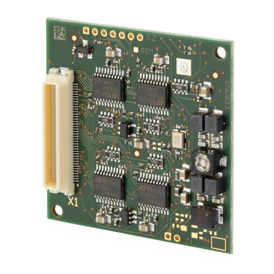
Summary of Contents for Feig Electronic ID CPR60
- Page 1 INSTALLATION ID CPR60 RFID Reader Module Model Article No. ID CPR60-A 5491.000.00 final – public (B) 2020-05-04 – M91210-1e-ID-B.docx...
- Page 2 FEIG ELECTRONIC call explicit attention that devices which are subject of this document are not designed with components and testing methods for a level of reliability suitable for use in or in connection with surgical implants or as critical components in any life support systems whose failure to perform can reasonably be expected to cause significant injury to a human.
-
Page 3: Table Of Contents
5. Standby / Low Power Card Detection 6. Technical Data 7. Approvals 7.1. Europa (CE) ........................14 7.2. USA (FCC) and Canada (IC) .................... 15 ANNEX Annex A: ID CPR60-DevBoard Reference Design ..............17 FEIG ELECTRONIC GmbH Page 3 of 21 M91210-1e-ID-B.docx... -
Page 4: Safety Instructions / Warning - Read Before Start-Up
IDENTIFICATION Installation ID CPR60 1. Safety Instructions / Warning - Read before start-up ! The device may only be used for the intended purpose designed by for the manufacturer. The operation manual should be conveniently kept available at all times for each user. -
Page 5: Characterization Id Cpr60
(polling) is available via the USB, COM and SPI interface. The functionality of the ID CPR60 is based on the well known CPR-family, like the reader module ID CPR74 or the wall-mount reader ID CPR50.10 and is compatible with them mainly. -
Page 6: Available Software Tools, Usb Driver And Firmware
2.1. Available Accessories). The ID CPR60-DevBoard offers 3 SAM sockets for ID-000 smart cards, 1 smart card connector for full size ID 1 cards and different connectors for the USB, COM and SPI interface. The integrated antenna can be used in combination with the CPR60 to communicate with transponders. -
Page 7: Dimensions
IDENTIFICATION Installation ID CPR60 3. Dimensions The ID CPR60 reader module has been designed for the integration into terminals, printers or handheld devices and so on. Figure 1: Dimension (Top View) Figure 2: Dimension (Side View) FEIG ELECTRONIC GmbH Page 7 of 21... -
Page 8: Installation And Wiring
X1 (Connector Type: Hirose DF17(2.5)-80DP-0.5V(57)) is the main connector for power supply, interfaces and control signals. The following table shows the pin-assignment of the connector. In- terfaces and functions are described from the ID CPR60 view (an input must be connected to one output or vice versa). - Page 9 IDENTIFICATION Installation ID CPR60 Function Remark Function Remark n.c. SAM3_VCC n.c. n.c. KCC_VCC (SAM 4) SAM1_CLK SPI_MISO* CPR60 is Slave SAM2_CLK SPI_MOSI* CPR60 is Slave USB DP* SPI_nCS** CPR60 Input USB DM* SPI_CLK** CPR60 Input n.c. n.c. n.c. SAM1_ RST n.c.
-
Page 10: Connector Ant
IDENTIFICATION Installation ID CPR60 4.2. Connector ANT The ID CPR60 module is equipped with an connector for an external 50 -antenna. The connection of the external antenna is possible via the U.FL connector „ANT“. ANT: (U.FL) Figure 4: Connection of an external antenna The technical description and hints for building external 50 -antennas can be taken from... -
Page 11: Standby / Low Power Card Detection
Installation ID CPR60 5. Standby / Low Power Card Detection The ID CPR60 offers a standby mode to reduce the power consumption to a minimum. The standby mode can be controlled by the host via input nLOW_PWR (see: 4.1. Connector X1). -
Page 12: Technical Data
IDENTIFICATION Installation ID CPR60 6. Technical Data Tab. 2: Technical data ID CPR60 Dimension (W x H x D) max. 41 mm x 41 mm x 6,5 mm Weight approx. 10 g Operating -25 °C up to +70 °C (-13 °F up to +158 °F) - Page 13 IDENTIFICATION Installation ID CPR60 Europe EN 300 330 FCC - Title 47 CFR Part 15 Radio Approval RSS-210 Issue 10 Canada RSS-Gen Issue 5 incl. Amendment 1 EN 301 489 EN 60950 Safety and Health EN 50364 WEEE - 2002/96/EC...
-
Page 14: Approvals
7. Approvals 7.1. Europa (CE) Hereby, FEIG ELECTRONIC GmbH declares that the radio equipment type ID CPR60 is in com- pliance with Directive 2014/53/EU. The full text of the EU declaration of conformity is available at the following internet address: http://www.feig.de/en/downloads-support/declarations-of-conformity.html... -
Page 15: Usa (Fcc) And Canada (Ic)
Warning: Changes or modification made to this equipment not expressly approved by FEIG ELECTRONIC GmbH may void the FCC authorization to operate this equipment. Installation with FCC / IC Approval: The reader module was tested according to the standard FCC - Title 47 CFR Part 15 §207, $209... - Page 16 IDENTIFICATION Installation ID CPR60 The manufacturer is obliged to test the terminal device together with the reader module according to the national FCC requirements according to 47 CFR Part15 §209 and §225 For this purpose the reader module must be set to normal operation, ScanMode. The Scan mode is switched on by SW...
-
Page 17: Annex
IDENTIFICATION Installation ID CPR60 ANNEX Annex A: ID CPR60-DevBoard Reference Design Figure 5: Top Overlay Print Figure 6: Top Layer FEIG ELECTRONIC GmbH Page 17 of 21 M91210-1e-ID-B.docx... - Page 18 IDENTIFICATION Installation ID CPR60 Figure 7: Bottom Layer FEIG ELECTRONIC GmbH Page 18 of 21 M91210-1e-ID-B.docx...
- Page 19 IDENTIFICATION Installation ID CPR60 Figure 8: CPR60-DevBoard Schematic Part 1 FEIG ELECTRONIC GmbH Page 19 of 21 M91210-1e-ID-B.docx...
- Page 20 IDENTIFICATION Installation ID CPR60 Figure 9: CPR60-DevBoard Schematic Part 2 FEIG ELECTRONIC GmbH Page 20 of 21 M91210-1e-ID-B.docx...
- Page 21 IDENTIFICATION Installation ID CPR60 Tab. 3: Bill of Material CPR60-DevBoard Symbol Description ANT 1 SMD U.FL HF-Print socket C1, C2, C3, C4, C5, C6, C7, C9, C10, C11, C12, C14, C15, C17 SMD capacitor 100.000pF/50V SMD capacitor 47pF/200V C31, C42...


Need help?
Do you have a question about the ID CPR60 and is the answer not in the manual?
Questions and answers