
Related Manuals for Feig Electronic OBID i-scan UHF ID ISC.MRU102-PoE-LED


Summary of Contents for Feig Electronic OBID i-scan UHF ID ISC.MRU102-PoE-LED
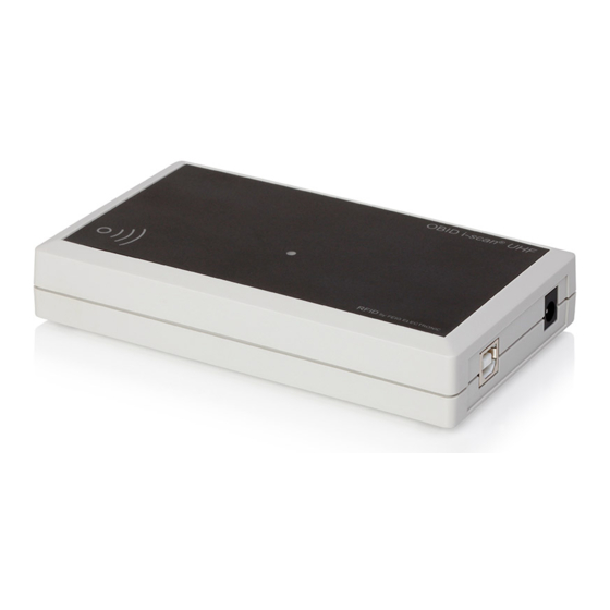
- Page 1 INSTALLATION ID ISC.MRU102-PoE-LED UHF Mid Range Reader with integrated antenna, buzzer and three additional LEDs final – public (B 2016-06-07 – M30119-1e-ID-B.docx...
- Page 2 FEIG ELECTRONIC call explicit attention that devices which are subject of this document are not designed with components and testing methods for a level of reliability suitable for use in or in connection with surgical implants or as critical components in any life support systems whose failure to perform can reasonably be expected to cause significant injury to a human.
- Page 3 • The following figure formats are used: 0...9: for decimal figures 0x00...0xFF: for hexadecimal figures, b0...1 for binary figures. • The hexadecimal value in brackets "[ ]" marks a control byte (command). FEIG ELECTRONIC GmbH Page 3 of 21 M30119-1e-ID-B.docx...
-
Page 4: Table Of Contents
7.3.1. USA (FCC) and Canada (IC) warning notices ............18 7.3.2. Label Information Reader Module ID ISC.MRMU102-A ..........19 7.3.3. Installation with FCC / IC Approval ................19 7.3.4. USA (FCC) and Canada (IC) approved antennas ............19 FEIG ELECTRONIC GmbH Page 4 of 21 M30119-1e-ID-B.docx... - Page 5 ® OBID i-scan Installation ID ISC.MRU102-PoE-LED ANNEX ANNEX A - Accessories ......................20 ANNEX B – Wall Mounting Kit ID ISC.MS.MR/PR-A .............. 21 FEIG ELECTRONIC GmbH Page 5 of 21 M30119-1e-ID-B.docx...
- Page 6 Although this device doesn't exceed the valid limits for electromagnetic fields you should keep a minimum distance of 25 cm between the device and your cardiac pacemaker and not stay in an immediate proximity of the device respective the antenna for some time. FEIG ELECTRONIC GmbH Page 6 of 21 M30119-1e-ID-B.docx...
-
Page 7: Performance Features Of The Reader Id Isc.mru102-Poe-Led
3 x SMA connectors for external antennas , 50Ohm 1 x integrated antenna Housed version with Ethernet- Interface, Power over Ethernet ID ISC.MRU102-POE-LED 1 x integrated antenna 3888.000.00 3 x optical and 1 x acoustic signaler FEIG ELECTRONIC GmbH Page 7 of 21 M30119-1e-ID-B.docx... -
Page 8: Assembly And Wiring
(see Appen1ix: ANNEX B – Wall Mounting Kit ID ISC.MS.MR/PR-A) NOTE: Before any installation the intended position of the reader should be tested for its suitabil- ity. 3.1. Dimensions Figure 1: Dimensions of the housing version (all dimensions are in mm) FEIG ELECTRONIC GmbH Page 8 of 21 M30119-1e-ID-B.docx... -
Page 9: Connections
Table 2: Connectors shows which connector can be used for the different interface cable. Figure 2: Connection overview Table 2: Connectors Connector Description Power supply 12 - 24VDC 10/100Tbase Ethernet interface with RJ-45 (PoE) FEIG ELECTRONIC GmbH Page 9 of 21 M30119-1e-ID-B.docx... -
Page 10: Power Supply
; 700mA Ambient Operating Temperature: 0°C to +40°C ID NET.12V-B-US 3887.000.00 NOTE: The power supply is supplied with a DC/ plug 2.5mm x 5.5mm. This is compatible with the readers socket X1. FEIG ELECTRONIC GmbH Page 10 of 21 M30119-1e-ID-B.docx... -
Page 11: Power Supply Via Power Over Ethernet (Poe)
PoE - power supply recommendations: Table 5: Recommended PoE Power Supply Article No. Name Description Power over Ethernet Supply 100-240V AC 3842.000.00 ID NET.PoEI13W-A (Continental European Plug), Output: 48V DC/ ; 0,5A FEIG ELECTRONIC GmbH Page 11 of 21 M30119-1e-ID-B.docx... -
Page 12: Ethernet Connection Via Connector X4 (10/100Tbase)
Table 6: Standard factory configuration of the Ethernet connection Network Address IP-Address 192.168.10.10 Subnet-Mask 255.255.0.0 Port 10001 DHCP NOTE: The reader provides a DHCP able TCP/IP interface. It is recommended to use a shielded twisted pair STP CAT5 cable. FEIG ELECTRONIC GmbH Page 12 of 21 M30119-1e-ID-B.docx... -
Page 13: Internal Antenna Ant4
40 cm. In combination with a near field transponder the maximum read range is approx. 5 cm. Figure 4: Position of the internal antenna FEIG ELECTRONIC GmbH Page 13 of 21 M30119-1e-ID-B.docx... -
Page 14: Control And Display Elements
The Buzzer can be controlled by the user. The volume of the Buzzer can be configured by Soft- ware command. Detailed information regarding the configuration of the Buzzer can be found in the Application Note N20212-0e-ID-E.pdf. FEIG ELECTRONIC GmbH Page 14 of 21 M30119-1e-ID-B.docx... -
Page 15: Technical Data
Notification Mode Supported Transponder Types EPC Class 1 Generation 2 ISO 18000-6-C (Upgrade Code required) Signaler optical 1 LED (multi-color: red and green) 3 LEDs (red, green and yellow) Signaler acoustical 1 Buzzer FEIG ELECTRONIC GmbH Page 15 of 21 M30119-1e-ID-B.docx... - Page 16 * Caution: Overheating of the device may result in performance losses. It is recommended to activate the RF of the reader only if there is a transponder in the detection range of an antenna. FEIG ELECTRONIC GmbH Page 16 of 21...
-
Page 17: Radio Approvals
Performance Classification according to ETSI EN 301 489: Class 2 7.2. Declaration of Conformity Hereby, FEIG ELECTRONIC GmbH declares that the radio equipment type ID ISC.MRU102 is in compliance with Directive 2014/53/EU. The full text of the EU declaration of conformity is available at the following internet address: www.feig.de. -
Page 18: Usa (Fcc) And Canada (Ic)
Warning: Changes or modification made to this equipment not expressly approved by FEIG ELECTRONIC GmbH may void the FCC authorization to operate this equipment. FEIG ELECTRONIC GmbH Page 18 of 21... -
Page 19: Label Information Reader Module Id Isc.mrmu102-A
Following antennas are approved by FCC according FCC Part 15 and IC Canada according RS210 • Integrated antenna (- 7dBic) FEIG ELECTRONIC GmbH Page 19 of 21 M30119-1e-ID-B.docx... - Page 20 Ambient Operating Temperature: 0°C to +40°C Power over Ethernet Supply 100-240V AC 3842.000.00 ID NET.PoEI13W-A (Continental European Plug), Output: 48V DC/ ; 0,5A 1691.000.01 ID ISC.MS.MR/PR-A Wall mounting kit for ID ISC.MR102 FEIG ELECTRONIC GmbH Page 20 of 21 M30119-1e-ID-B.docx...
- Page 21 Remove the screws from the back side of the Reader. • Attach the individual wall hangers using the screws supplied with the mounting kit. Figure 5: Mounting wall hangers Figure 6: Mounting drill dimensioning (all dimensions in mm) FEIG ELECTRONIC GmbH Page 21 of 21 M30119-1e-ID-B.docx...
Need help?
Do you have a question about the OBID i-scan UHF ID ISC.MRU102-PoE-LED and is the answer not in the manual?
Questions and answers