Feig Electronic ID ISC.MRMU102-A Installation Manual
Hide thumbs
Also See for ID ISC.MRMU102-A:
- User manual (64 pages) ,
- Installation manual (36 pages) ,
- Installation manual (24 pages)
Table of Contents
Advertisement
Quick Links
Test report no. 21012267
EUT: MRU102
FCC ID: PJMMRU102A
FCC Title 47 CFR Part 15
Date of issue: 2021-06-24
Annex acc. to FCC Title 47 CFR Part 15
relating to
Feig Electronic GmbH
MRU102
Annex no. 5
User Manual
Functional Description
Title 47 - Telecommunication
Part 15 - Radio Frequency Devices
Subpart C – Intentional Radiators
ANSI C63.4-2014
ANSI C63.10-2013
Date: 2019-11-20
Created: Trepper
Controlled: Ftouhi
Released: Hittig-Rademacher
Vers. no. 3.19
TÜV NORD Hochfrequenztechnik GmbH & Co. KG
Tel.: +49 221 8888950
LESKANPARK, Gebäude 10, Waltherstr. 49-51, 51069 Köln, Germany
Advertisement
Table of Contents

Subscribe to Our Youtube Channel
Related Manuals for Feig Electronic ID ISC.MRMU102-A


Summary of Contents for Feig Electronic ID ISC.MRMU102-A
- Page 1 EUT: MRU102 FCC ID: PJMMRU102A FCC Title 47 CFR Part 15 Date of issue: 2021-06-24 Annex acc. to FCC Title 47 CFR Part 15 relating to Feig Electronic GmbH MRU102 Annex no. 5 User Manual Functional Description Title 47 - Telecommunication Part 15 - Radio Frequency Devices Subpart C –...
- Page 2 Test report no. 21012267 EUT: MRU102 FCC ID: PJMMRU102A FCC Title 47 CFR Part 15 Date of issue: 2021-06-24 User Manual / Functional Description of the test equipment (EUT) Date: 2019-11-20 Created: Trepper Controlled: Ftouhi Released: Hittig-Rademacher Vers. no. 3.19 TÜV NORD Hochfrequenztechnik GmbH &...
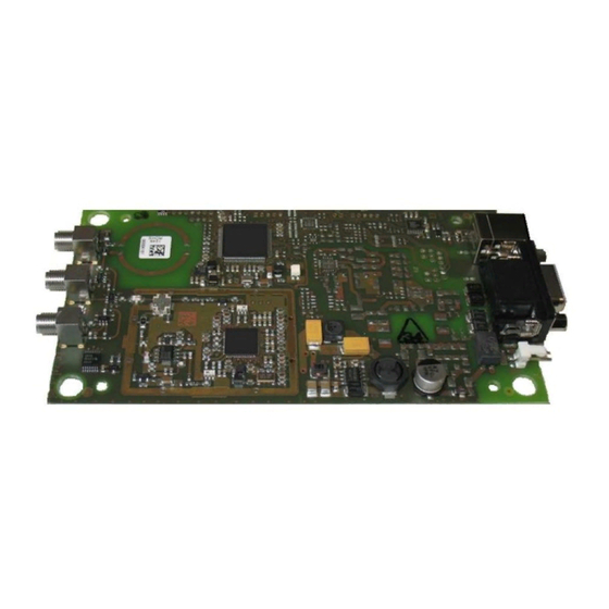
- Page 3 IDENTIFICATION === Ende der Liste für T extmar ke Dec kbl att === INSTALLATION MANUAL ID ISC.MRMU102-A / ID ISC.MRMU102-POE UHF Mid Range Reader Module M21112-4e-ID-B...
- Page 4 Composition of the information in this document has been done to the best of our knowledge. FEIG ELECTRONIC GmbH does not guarantee the correctness and completeness of the details given in this manual and may not be held liable for damages ensuing from incorrect or incomplete information. Since, despite all our efforts, errors may not be completely avoided, we are always grateful for your useful tips.
-
Page 5: Table Of Contents
Performance Features of the Reader Available Reader Types ....................6 Assembly and Wiring Viewing and Dimensions ....................7 3.1.1 Viewing and Dimensions ID ISC.MRMU102-A ............7 3.1.2 Viewing and Dimensions ID ISC.MRMU102-POE ..........8 Connections Connections ID ISC.MRMU102-A ..................9 4.1.1... - Page 6 IDENTIFICATION ID ISC.MRMU102 Technical Data ANHANG ANNEX A - Accessories ....................22 Page 4 of 23...
- Page 7 IDENTIFICATION ID ISC.MRMU102 1 Safety Instructions The device may only be used for the intended purpose designed by for the manufacturer. ► The operation manual should be conveniently kept available at all times for each user. ► Unauthorized changes and the use of spare parts and additional devices which have not been sold or ►...
-
Page 8: Performance Features Of The Reader
ID ISC.MRMU102 2 Performance Features of the Reader The reader modules ID ISC.MRMU102-A and ID ISC.MRMU102-POE are designed for reading of passive data carriers, so-called „Smart Labels“ at an operating frequency in the UHF band between 860 MHz and 960 MHz. -
Page 9: Assembly And Wiring
NOTE: Before any installation the intended position of the reader should be tested for its suitability. 3.1 Viewing and Dimensions 3.1.1 Viewing and Dimensions ID ISC.MRMU102-A Figure 1: Dimensions ID ISC.MRMU102-A (all dimensions are in mm) Page 7 of 23... -
Page 10: Viewing And Dimensions Id Isc.mrmu102-Poe
IDENTIFICATION ID ISC.MRMU102 3.1.2 Viewing and Dimensions ID ISC.MRMU102-POE Figure 2: Dimensions ID ISC.MRMU102-POE (all dimensions in mm) Page 8 of 23... -
Page 11: Connections
ID ISC.MRMU102 4 Connections 4.1 Connections ID ISC.MRMU102-A The module version of the reader is equipped with an asynchronous RS232 Interface (X2) and a USB Interface (X3). The Table below shows which connector can be used for the different interface cable. -
Page 12: Rs232 Interface On Connector X2
IDENTIFICATION ID ISC.MRMU102 For connection of the power supply a special DC-Connector from the manufacturer Molex is required. The necessary components of the DC-Connector are listed in Table 3 Table 3: Components of the required DC-Connector Component Manufacturer Article ID of Manufacturer Housing Molex 22-01-3027... - Page 13 IDENTIFICATION ID ISC.MRMU102 Interface parameter can be configured via software protocol (e.g. ISOStart). Further information can be found in the System Manual H10410-Xe-ID-B.pdf of the reader. Page 11 of 23...
-
Page 14: Usb Interface On Connector X3
IDENTIFICATION ID ISC.MRMU102 4.1.3 USB Interface on Connector X3 There is a USB-socket X3 on board for the connection of the USB-Interface. The pinout is standardized. The data rate is reduced to 12 Mbit (USB full speed). A standard USB-cable can be used. Figure 4: USB interface for host communication NOTE: •... -
Page 15: Connections Id Isc.mrmu102-Poe
IDENTIFICATION ID ISC.MRMU102 4.2 Connections ID ISC.MRMU102-POE The module version of the reader is equipped with an Ethernet Interface (X4). For transponder communication up to 3 external antennas can be connected. In addition an integrated antenna is available. The Table below shows which connector can be used for the different interface cable. Table 6: Connectors Connector Description... -
Page 16: Ethernet-Interface On Connector X4 (10/100Tbase)
IDENTIFICATION ID ISC.MRMU102 Figure 5: LAN and PoE connection NOTE: The reader has to be supplied by a limited power supply according EN 62368-1 Chapter Q.1, or with a NEC Class 2/LPS certified power supply. It must be ensured that the reader is supplied with 42,5 V DC (48 V DC – cable losses) at least. The maximum cable distance for Ethernet is 100m. - Page 17 IDENTIFICATION ID ISC.MRMU102 The prerequisite for using TCP/IP protocol is that each device has a unique address on the network. All Readers have a factory set IP address. Interface parameter can be configured via software protocol (e.g. ISOStart). Table 9: Standard factory configuration of the Ethernet connection Network Address IP-Address...
-
Page 18: Antenna Terminals
IDENTIFICATION ID ISC.MRMU102 4.3 Antenna Terminals 4.3.1 External Antenna ANT 1 - 3 Three SMA sockets are provided on the circuit board for connecting of the external antennas. The maximum tightening torque for the SMA socket is 0.45 Nm. CAUTION: Higher tightening torque will damage the connector. -
Page 19: Control And Display Elements
IDENTIFICATION ID ISC.MRMU102 5 Control and Display Elements 5.1 LED The Reader’s LED can be configured through software. The following Table 11: Default Configuration of the LEDs shows the default setting. Table 11: Default Configuration of the LEDs Abbreviation Description "RUN "... -
Page 20: Radio Approvals
6 Approvals 6.1 Declaration of Conformity (CE) Hereby FEIG ELECTRONIC GmbH declares that the radio equipment type ID ISC.MRMU102 is in compliance with Directive 2014/53/EU. The full text of the EU declaration of conformity is available at the following internet address: https://www.feig.de/en/service/eu-declarations-of-conformity/... -
Page 21: Usa (Fcc) And Canada (Ic)
Warning: Changes or modification made to this equipment not expressly approved by FEIG ELECTRONIC GmbH may void the FCC authorization to operate this equipment. 6.2.1 Label Information Reader Module The following information must be placed at the outer side of the housing in which the reader is mounted. -
Page 22: Installation With Fcc / Ic Approval
IDENTIFICATION ID ISC.MRMU102 6.2.2 Installation with FCC / IC Approval FCC-/IC-NOTICE: To comply with FCC Part 15 Rules in the United States / with IC Radio Standards in Canada, the system must be professionally installed to ensure compliance with the Part 15 certification / IC certification. - Page 23 IDENTIFICATION ID ISC.MRMU102 7 Technical Data Mechanical Data 60 g Weight Dimensions (W x H x D) 137 mm x 77 mm x 17 mm Electrical Data Power supply 12 V DC to 24 V DC • MRMU102-A 12 V DC to 24 V DC •...
- Page 24 IDENTIFICATION ID ISC.MRMU102 8 ANHANG 8.1 ANNEX A - Accessories The following accessories are available for the Reader. Table 12: Accessories Article No. Part No. Description 1686.000.00 ID CAB.USB-A USB-cable 2,5m 1690.000.00 ID CAB.RS-A Serial data cable Power Supply 95 - 265V AC Input Voltage, (Continental European Plug), 1688.002.00 ID NET.12V-B-EU...
- Page 25 IDENTIFICATION ID ISC.MRMU102 ID ANT.C2-B UHF Antenna Cable SMA/TNC 2 m 5241.001.00 Antenna Cable 2m for antennas ID ANT.U580/290 and ID ANT.U290/290 ID ANT.C6-B UHF Antenna Cable SMA/TNC 6 m 5241.002.00 Antenna Cable 6m for antennas ID ANT.U580/290 and ID ANT.U290/290 Page 23 of 23...
- Page 26 Free Flow Tolling systems Circular polarized allrounder Modern and robust The UHF antennas from FEIG ELECTRONIC are With the combination of elegant design and high characterized by their high performance and precise protection class IP65 the antennas can be used for both, tuning for the various UHF operating frequencies.
- Page 27 UHF Long Range Antennas for various applications UHF RAIN antennas from FEIG ELECTRONIC offer greatest possible variability with elegant design and robust appearance. Product details UHF Antennas ID ANT.U290/290 ID ANT.U580/290 Dimensions 288 mm x 288 mm x 65 mm*...
- Page 28 Ú UHF RFID Antennas ID ISC.ANT.U170/170 / U270/270 / U600/270 SPECIAL FEATURES Ú Circular Polarization for optimized reading performance Ú Available for EU and FCC Frequencies Ú IP 65 for outdoor applications Ú Unique design Ú Usable with all available UHF readers Ú...
- Page 29 - 25 °C up to 80 °C - 25 °C up to 80 °C Antennas are compatible with any current UHF reader system. * Tolerances ± 0.5 mm FEIG ELECTRONIC reserves the right to change specification without notice at any time. State of information: April 2015.
Need help?
Do you have a question about the ID ISC.MRMU102-A and is the answer not in the manual?
Questions and answers