
Related Manuals for Feig Electronic ID ISC.ANT.U500/270


Summary of Contents for Feig Electronic ID ISC.ANT.U500/270
-
Page 1: Id Isc.ant.u500/270
INSTALLATION ID ISC.ANT.U500/270 Type GA and GB UHF-Gate Draft - public (B) –M71060-1e-ID-B 2017-11-29... - Page 2 FEIG ELECTRONIC call explicit attention that devices which are subject of this document are not designed with components and testing methods for a level of reliability suitable for use in or in connection with surgical implants or as critical components in any life support systems whose failure to perform can reasonably be expected to cause significant injury to a human.
-
Page 3: Table Of Contents
Antenna ID ISC.ANT.U500/270 Type GA ..............7 3.1.2 Antenna ID ISC.ANT.U500/270 Type GB ..............7 Performance Features of the ID ISC.ANT.U500/270 Antennas ........ 8 Performance Features of the People Counter (ID ISC.UPC) ........8 Available Antenna Types ..................10 Installation and Wiring Mounting Preparation .................... - Page 4 FCC Reader according to FCC 47 Part 15 ............. 50 6.1.3 USA (FCC) ......................51 6.1.3.1 Antenna ID ISC.ANTU500/270 GA/GB ............51 Technical Data Antenna ID ISC.ANT.U500/270 Type GA and GB ............ 52 FEIG ELECTRONIC GmbH Page 4 of 54 M71060-1e-ID-B...
-
Page 5: Safety Instructions / Warning - Read Before Start-Up
Identification Installation ID ISC.ANT.U500/270–GA/-GB UHF-Gate Safety Instructions / Warning - Read before Start-Up ! The device may only be used for the intended purpose designed by for the manufacturer. The operation manual should be conveniently kept available at all times for each user. -
Page 6: Maintenance
Installation ID ISC.ANT.U500/270–GA/-GB UHF-Gate Maintenance The antenna ID ISC.ANT.U500/270 is a design product with high quality surfaces, and should al- ways be handled with caution. The antenna was designed to work reliably and flawlessly for years without special maintenance. Attention! The surfaces should be cleaned with a clean, soft cloth dampened in a dishwashing liquid –... -
Page 7: Performance Features
Performance Features 3.1 Scope of delivery 3.1.1 Antenna ID ISC.ANT.U500/270 Type GA Antenna ID ISC.ANT.U500/270 incl. UHF Reader Module and People Counter with alarm LED and Buzzer. Wide range power supply ID ISC.NET24V-B 100-240V/ 24V (without power cable with IEC plug) ... -
Page 8: Performance Features Of The Id Isc.ant.u500/270 Antennas
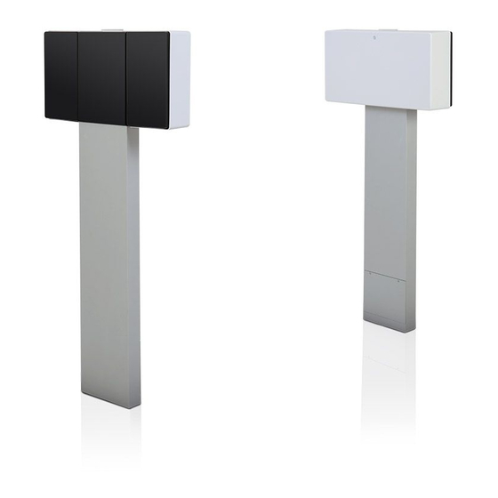
ID ISC.ANT.U500/270–GA/-GB UHF-Gate 3.2 Performance Features of the ID ISC.ANT.U500/270 Antennas The ID ISC.ANT.U500/270-GA antenna is a version with integrated Long Range Reader ID ISC.LRU1002 additional Alarm LED light, Alarm buzzer and People Counter UPC . The ID ISC.ANT.U500/270-GB antenna is a version with integrated Alarm LED light mounted. - Page 9 Identification Installation ID ISC.ANT.U500/270–GA/-GB UHF-Gate Infra red detection zone of a single gate Infra red detection zone of a single gate (side view) (top view) ISC.ANT.U500/270-GA ISC.ANT.U500/270-GB Fig. 2: Views of the detection area The People Counter board and the Infra red Sensor is mounted in the housing of the antenna type ID ISC.ANT.U500/270-GA.
-
Page 10: Available Antenna Types
Identification Installation ID ISC.ANT.U500/270–GA/-GB UHF-Gate 3.4 Available Antenna Types The following products are currently available: Antenna Type Description ID ISC.ANT.U.500/270-GA Antenna with Reader, Multiplexer , Alarm LED light, Alarm Sounder, people counter and 24 VDC power supply. Order No. 4884.000.00 ID ISC.ANT.U500/270-GB... -
Page 11: Mounting Preparation
Identification Installation ID ISC.ANT.U500/270–GA/-GB UHF-Gate 4.1 Mounting Preparation For the assembly of the antenna it has to be carefully unpacked and the antenna base to be opened. This is done as described in the following steps: 1. Place the packed antenna on the floor with the top side facing up. Carefully open the box and then remove the antenna. -
Page 12: Installing The Antenna
Identification Installation ID ISC.ANT.U500/270–GA/-GB UHF-Gate 4.2 Installing the antenna 4.2.1 Dimensions of antenna The overall dimensions of the antenna are shown in Fig. 5 Fig. 5: Antenna outside dimensions All dimensions are in mm with general tolerance according to ISO 2768 m (mean). -
Page 13: Drilling The Mounting Holes
Identification Installation ID ISC.ANT.U500/270–GA/-GB UHF-Gate 4.2.2 Drilling the Mounting Holes If the position of the antennas has been marked or determined, the mounting holes and the holes for the cable entry, can be marked and drilled for the antenna foot. -
Page 14: Installing The Antenna On The Floor
Identification Installation ID ISC.ANT.U500/270–GA/-GB UHF-Gate 4.2.3 Installing the Antenna on the floor The antenna will be mounted on the floor. Please note, the open side of the steel foot should face towards the middle of the aisle. Step Action Note... - Page 15 Identification Installation ID ISC.ANT.U500/270–GA/-GB UHF-Gate Step Action Note Put the cables through the cable opening. Put the antenna with the mounting holes on the anchors and screw it tight. FEIG ELECTRONIC GmbH Page 15 of 54 M71060-1e-ID-B...
- Page 16 Identification Installation ID ISC.ANT.U500/270–GA/-GB UHF-Gate Step Action Note Connect the cables of the interface and the power supply. Connect the antenna cables to the corresponding antenna cables of antenna B 1 with 1 2 with 2 FEIG ELECTRONIC GmbH Page 16 of 54...
- Page 17 Identification Installation ID ISC.ANT.U500/270–GA/-GB UHF-Gate Step Action Note Put the power supply into the antenna foot. If needed the antenna could be adjusted vertically with the adjustable feet. FEIG ELECTRONIC GmbH Page 17 of 54 M71060-1e-ID-B...
- Page 18 Identification Installation ID ISC.ANT.U500/270–GA/-GB UHF-Gate Step Action Note Close the antenna with the antenna cover. FEIG ELECTRONIC GmbH Page 18 of 54 M71060-1e-ID-B...
-
Page 19: Disassembly Of The Antenna From The Antenna Foot (For Replacement/Repair)
Identification Installation ID ISC.ANT.U500/270–GA/-GB UHF-Gate 4.2.4 Disassembly of the Antenna from the Antenna foot (for replacement/repair) The antenna will be mounted on the floor. Please note, the open side of the steel foot should face towards the middle of the aisle. - Page 20 Identification Installation ID ISC.ANT.U500/270–GA/-GB UHF-Gate Step Action Note Disconnect all cables in the antenna foot. FEIG ELECTRONIC GmbH Page 20 of 54 M71060-1e-ID-B...
- Page 21 Identification Installation ID ISC.ANT.U500/270–GA/-GB UHF-Gate Step Action Note Unscrew the screw nuts in the antenna foot. Pull the antenna with the thread bolts and the cables out of the antenna foot. FEIG ELECTRONIC GmbH Page 21 of 54 M71060-1e-ID-B...
- Page 22 Identification Installation ID ISC.ANT.U500/270–GA/-GB UHF-Gate Step Action Note Close the antenna with the antenna cover. If antenna must be sent for repair, it must be sent complete with cables and power supply. FEIG ELECTRONIC GmbH Page 22 of 54 M71060-1e-ID-B...
-
Page 23: Typical Antenna Configuration (Gate With Two Antennas)
The standard configuration of a gate with three-dimensional tag orientation consists of one ID ISC.ANT.U500/270-GA antenna with reader and one ID ISC.ANT.U500/270-GB. If a tag moves, at horizontal line through the gate, it can be detected with a high reliability. -
Page 24: Gate Configuration And Setup Using Antennas
5.2 Gate Configuration and Setup using Antennas 5.2.1 Required Components To set up the gate you need the following components: Qty. 1 ID ISC.ANT.U500/270-GA (incl. Qty. 1 ID ISC.NET24V-B Power Supply Unit) Qty. 1 ID ISC. ANT.U500/270-GB Power cable, interface cable LAN TCP/IP... -
Page 25: Configuration Of The Gate Antennas
Identification Installation ID ISC.ANT.U500/270–GA/-GB UHF-Gate 5.2.2 Configuration of the Gate Antennas Almost, all cable should be mounted already. Normally, the antenna cable 1+2 from antenna Type GB has to be connected antenna cable 1+2 at the type GA antenna 1:1 Fig. -
Page 26: Interface Connections
Identification Installation ID ISC.ANT.U500/270–GA/-GB UHF-Gate 5.2.3 Interface Connections 5.2.3.1 LAN / TCP/IP The Reader has an integrated 10 / 100 Base-T network port for an RJ-45. Connection is made on X1 and has an automatic “Crossover Detection” according to the 1000 Base-T Standard. -
Page 27: Usb Mini Interface On Connector X3
Identification Installation ID ISC.ANT.U500/270–GA/-GB UHF-Gate 5.2.3.1 USB Mini Interface on connector X3 The reader is equipped with a USB on-the-go interface. This can either be used to connect the reader to a host system or by means of a special on-the-go adaptor for connection of a USB mem- ory stick to the reader. -
Page 28: Reader/Antenna Configuration
Identification Installation ID ISC.ANT.U500/270–GA/-GB UHF-Gate 5.2.4 Reader/Antenna Configuration To configure the antennas, open the ISOStart software and read out the current configuration of the Reader: Step Action Note Start ISO Start Software Select „Detect“ Use USB Port or default TCP/IP address 192.168.10.10... - Page 29 Identification Installation ID ISC.ANT.U500/270–GA/-GB UHF-Gate Step Action Note Select „Options => Program“ Select „Expert Mode“ and confirm with OK. Select “Logical View” FEIG ELECTRONIC GmbH Page 29 of 54 M71060-1e-ID-B...
- Page 30 Identification Installation ID ISC.ANT.U500/270–GA/-GB UHF-Gate Afterwards set the Interface settings and the operating mode: Step Action Note Select “Configuration” Select -HostInterface -LAN Set LAN settings. Set by clicking on „Apply“. Select command “System reset” Confirm with “Send” FEIG ELECTRONIC GmbH...
- Page 31 Identification Installation ID ISC.ANT.U500/270–GA/-GB UHF-Gate Select -Operating Mode -Mode Set to Buffered Read Mode Set by clicking on „Apply“. Select -Air Interface -Region Set right “Region”. Set by clicking on „Apply“. FEIG ELECTRONIC GmbH Page 31 of 54 M71060-1e-ID-B...
-
Page 32: Testing The Gate Antenna
Identification Installation ID ISC.ANT.U500/270–GA/-GB UHF-Gate 5.3 Testing the Gate Antenna After configuring and installing the gate antenna, you can check for proper function using a reader, the ISOStart service software and a Transponder. 5.3.1 Reading a Serial Number Step Action... -
Page 33: Testing The Performance
Identification Installation ID ISC.ANT.U500/270–GA/-GB UHF-Gate 5.3.2 Testing the performance An alarm will be notified by the Alarm LED light of the antenna and the Alarm buzzer. See also 5.4.1 Reader Setting for Alarm Indicators In this test the capture area of the gate antenna is checked. For different tags or other configurations the ranges and read areas may differ. - Page 34 Identification Installation ID ISC.ANT.U500/270–GA/-GB UHF-Gate The following may result in faulty readings: Antenna improperly installed (orientation, antenna distance, check cabling) Metal near the antennas is detuning or interfering with them. Transponder too insensitive, detuned or defective , see as well 5.1 Project Notes Antenna.
-
Page 35: Setting The Alarm Indicators (Alarm Buzzer And Alarm Led Lights)
Identification Installation ID ISC.ANT.U500/270–GA/-GB UHF-Gate 5.4 Setting the Alarm Indicators (Alarm buzzer and Alarm LED lights) 5.4.1 Reader Setting for Alarm Indicators The Alarm buzzer and the Alarm LED of antenna type GA and GB is constructed by the UPC. -
Page 36: Reader Setting For Alarm Conditions
Identification Installation ID ISC.ANT.U500/270–GA/-GB UHF-Gate 5.4.2 Reader Setting for Alarm conditions Step Action Note Start ISOStart Software Select “Configuration” and click on “Read” to read the complete configuration. Select -Operating Mode Select “Alarm Method” Select “Bank” if “Alarm on AFI value” is selected then Set “Alarm address”... -
Page 37: Reducing False Alarms
Identification Installation ID ISC.ANT.U500/270–GA/-GB UHF-Gate 5.4.3 Reducing false Alarms By creating a blacklist, all transponders placed in the surrounding of the gate will be read and stored in the blacklist, this will reduce/avoid false alarms. Step Action Note Start ISOStart Software Select “Configuration”... - Page 38 Identification Installation ID ISC.ANT.U500/270–GA/-GB UHF-Gate Among other information a blacklist overflow is indicated FEIG ELECTRONIC GmbH Page 38 of 54 M71060-1e-ID-B...
-
Page 39: Programming A Transponder With The Afi Or Alarm Byte
Identification Installation ID ISC.ANT.U500/270–GA/-GB UHF-Gate 5.4.4 Programming a Transponder with the AFI or Alarm Byte If the Transponders will remain on the object when leaving the storage location, they must first be disabled. This is generally done by writing to a particular area of the Transponder. -
Page 40: Activating The Automatic Mode
Identification Installation ID ISC.ANT.U500/270–GA/-GB UHF-Gate 5.5 Activating the Automatic Mode The gate has to be used in one of the Automatic Modes (Buffered Read or Notification Mode) to get a maximum performance. For more information, see System Manual ID ISC.LRU1002 Which mode the most suitable is for your application has to be defined in advance. -
Page 41: Testing The Gate In Buffered Read Mode
Identification Installation ID ISC.ANT.U500/270–GA/-GB UHF-Gate 5.5.1 Testing the Gate in Buffered Read Mode Select “Buffered Read Mode” Click on “Start” Walk through the gate from both directions with a valid transponder. Transponder data will be displayed. FEIG ELECTRONIC GmbH Page 41 of 54... -
Page 42: Testing The People Counter In Buffered Read Mode
Identification Installation ID ISC.ANT.U500/270–GA/-GB UHF-Gate 5.5.2 Testing the People Counter in Buffered Read Mode Step Action Note Select „Commands“ Select “Peripheral Device Commands” "People Counter" Select Command „Set People Counter Values“ with setting "0" Confirm with „Send“ Select Command „Get People Counter Values“... - Page 43 Identification Installation ID ISC.ANT.U500/270–GA/-GB UHF-Gate All counter values should be 0 then Walk through the gate from both directions. Counter 1 | Counter 2 Select Command „Get People Counter Values“ Confirm with „Send“ Counter values different to 0 will be displayed In Buffered Read Mode the People Counter has to be polled by the Host Application to get the data.
-
Page 44: Configuration And Test In Notification Mode
Identification Installation ID ISC.ANT.U500/270–GA/-GB UHF-Gate 5.5.3 Configuration and Test in Notification Mode In Notification Mode the Reader sends the People Counter Data automatically to the Host. The following configuration hast o be done: Step Action Note Select „Configuration“ Operating Mode... - Page 45 Identification Installation ID ISC.ANT.U500/270–GA/-GB UHF-Gate Set right Port number, e.g. 20001; value defined from Computer that shall receive the gate data The same TCP/IP Address and Port Address is valid for the Notification Channel of the People Counter and Notification Channel of the data Click on “Apply”...
-
Page 46: Reader Diagnostic
Identification Installation ID ISC.ANT.U500/270–GA/-GB UHF-Gate 5.6 Reader Diagnostic An error of the reader/gate will be displayed by the diagnostic LED in the type GA antenna. Detailed information about the error could be analyzed with the ISO-Start program. Step Action Note Reader Diagnostic Select “Commands”... - Page 47 Identification Installation ID ISC.ANT.U500/270–GA/-GB UHF-Gate Step Action Note Coding: Error signaling over special diagnostic LEDs of A side Coding: If the antenna cables from antenna type A to antenna type B have not been connected in the right way or there is an error, the...
-
Page 48: Configure The Reader In Accordance With National Rf Regulations
Identification Installation ID ISC.ANT.U500/270–GA/-GB UHF-Gate Configure the reader in accordance with national RF regulations To achieve the optimum reading performance it might be sensible to increase the reader output power compared to the default settings given in 5.2.4. The maximum allowed power depends on the used reader type (EU / FCC) and the regulation in the country were the reader is used. -
Page 49: Eu Reader According To En 302 208
Identification Installation ID ISC.ANT.U500/270–GA/-GB UHF-Gate 6.1.1 EU reader according to EN 302 208 According to the standard EN 302 208 the maximum radiated power is 2 W e.r.p. (Effective Radi- ated Power) in countries of the European Union. The in the reader configured output power P depends on the antenna gain in dBi and the attenuation of the antenna cable. -
Page 50: Fcc Reader According To Fcc 47 Part 15
According to the FCC approval, Title 47, Part 15 the maximum output power of the reader is limited to 1 W (30dBm). The maximum radiated power of the antenna must not be more than 4 W e.i.r.p, (corresp. to 36dBm e.i.r.p or 33.75 dBm e.r.p. resp). As for ID ISC.ANT.U500/270-FCC: Antenna: 9dBic, circularly polarised 0m cable ... -
Page 51: Usa (Fcc)
Identification Installation ID ISC.ANT.U500/270–GA/-GB UHF-Gate 6.1.3 USA (FCC) 6.1.3.1 Antenna ID ISC.ANTU500/270 GA/GB Product name: ID ISC.ANTU500/270-GA/-GB Antenna name: ID ISC.ANTU500/270 Type GA / GB Reader name: ID ISC.LRU1002 FCC ID: This device complies with Part 15 of the FCC Rules Notice for USA Operation is subject to the following two conditions. -
Page 52: Technical Data
Identification Installation ID ISC.ANT.U500/270–GA/-GB UHF-Gate Technical Data 7.1 Antenna ID ISC.ANT.U500/270 Type GA and GB Mechanical Data Housing UV stabilized ABS Aluminum Antenna foot Dimensions ( W x H x D ) 506 mm x 1102 mm x 103 mm 3 mm –... - Page 53 Identification Installation ID ISC.ANT.U500/270–GA/-GB UHF-Gate Maximum transmitting power per 2 W but consider limit due to national RF antenna regulations Permissible overall transmitting power per antenna gate – EU-territory (per EN 302 208) 0.8 W for Ant. 1 and 3 1.1 W for Ant.
- Page 54 Identification Installation ID ISC.ANT.U500/270–GA/-GB UHF-Gate Ambient Conditions Temperature range – Operating 0°C to +55 °C – Storage –25 °C to +80 °C FEIG ELECTRONIC GmbH Page 54 of 54 M71060-1e-ID-B...
Need help?
Do you have a question about the ID ISC.ANT.U500/270 and is the answer not in the manual?
Questions and answers