Feig Electronic OBID i-scan ID ISC.LRM2500-A Installation Manual
Long range reader
Hide thumbs
Also See for OBID i-scan ID ISC.LRM2500-A:
- Installation manual (8 pages) ,
- Installation manual (32 pages) ,
- Installation manual (30 pages)

Subscribe to Our Youtube Channel
Related Manuals for Feig Electronic OBID i-scan ID ISC.LRM2500-A


Summary of Contents for Feig Electronic OBID i-scan ID ISC.LRM2500-A
- Page 1 INSTALLATION ID ISC.LRM2500-A Long Range Reader (English) final – public (B) 2015-10-15 – M10210-4e-ID-B.docx...
- Page 2 FEIG ELECTRONIC GmbH assumes no responsibility for the use of any information contained in this docu- ment and makes no representation that they free of patent infringement. FEIG ELECTRONIC GmbH does not convey any license under its patent rights nor the rights of others.
-
Page 3: Table Of Contents
Ethernet-Interface on X1 (10/100 Base-T) .............. 24 Operating and Display Elements LEDs .......................... 25 Reset-Buttons ......................26 Radio Approvals Europe (CE) ....................... 27 USA (FCC) and Canada (IC) ..................28 Technical Data FEIG ELECTRONIC GmbH Page 3 of 30 M10210-4e-ID-B.docx... -
Page 4: Safety Instructions / Warning - Read Before Start-Up
Although this device doesn't exceed the valid limits for electromagnetic fields you should keep a minimum distance of 25 cm between the device and your cardiac pacemaker and not stay in the immediate proximity of the device’s antenna for any length of time. FEIG ELECTRONIC GmbH Page 4 of 30 M10210-4e-ID-B.docx... -
Page 5: Performance Features Of Reader Family Id Isc.lrm2500
Host und Embedded Linux ID ISC.LR2500-A Housing version with RS232/485- / USB- / LAN-Interface, USB- Host und Embedded Linux ID ISC.LR2500-B Module version with RS232/485- / USB- / LAN-Interface Table 1: Available Reader types FEIG ELECTRONIC GmbH Page 5 of 30 M10210-4e-ID-B.docx... -
Page 6: Installation And Mounting
4.5 mm holes located in each corner of the base plate (see: Figure 1). 16,3 ø 4,5 mm ø 4,5 mm ø 4,5 mm* ø 4,5 mm* ø 4,5 mm* Figure 1: Scale drawing of the Reader module with mounting plate FEIG ELECTRONIC GmbH Page 6 of 30 M10210-4e-ID-B.docx... - Page 7 Reader. In such cases the Reader regulates its output power down until the upper temperature limit of its final stage fallen down again. FEIG ELECTRONIC GmbH Page 7 of 30 M10210-4e-ID-B.docx...
-
Page 8: Terminals
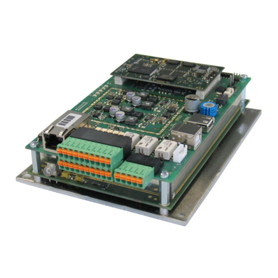
® OBID i-scan Installation ID ISC.LRM2500-A 3.2 Terminals Figure 2 shows the terminals and control elements of the ID ISC.LRM2500-A Figure 2: Reader terminals FEIG ELECTRONIC GmbH Page 8 of 30 M10210-4e-ID-B.docx... -
Page 9: Antenna Connection
When connecting an antenna, ensure that it does not exceed the permissible limits pre- scribed by the national regulations for radio frequency devices. Figure 3: Antenna line with EMC ring cores FEIG ELECTRONIC GmbH Page 9 of 30 M10210-4e-ID-B.docx... -
Page 10: Supply Voltage
EMC ring cores 28 mm x 20 mm. The power supply line must be wound around the ring core for at least 5 turns. The distance between the Reader termination and the ring core should be maximum 10 cm. FEIG ELECTRONIC GmbH Page 10 of 30 M10210-4e-ID-B.docx... -
Page 11: Fuse F1
Figure 5: Position of the fuse F1 Attention!: The 24V voltage for supplying the internal and external DC voltage on X2 for the dig- ital inputs and outputs is not protected by the fuse F1. FEIG ELECTRONIC GmbH Page 11 of 30 M10210-4e-ID-B.docx... -
Page 12: X2: Optocoupler Inputs (X2 / In1, In2, In3)
All 3 inputs are identical and may therefore be configured individually. 24 V Uext 24 V Uext 24 V Uext Figure 7: External power supply for the optocouplers FEIG ELECTRONIC GmbH Page 12 of 30 M10210-4e-ID-B.docx... - Page 13 20mA. For voltages of less than 10V a part of the series resistance must be jumpered (J1, J3, J5) accordingly. Figure 9: Position of the Jumper J1- J9 FEIG ELECTRONIC GmbH Page 13 of 30 M10210-4e-ID-B.docx...
- Page 14 The internal 24V voltage for supplying the DC voltage on the digital inputs is not protected by the fuse F1. Using internal and external voltage at the same time can destroy the reader. FEIG ELECTRONIC GmbH Page 14 of 30 M10210-4e-ID-B.docx...
-
Page 15: Optocoupler Outputs (X2 / Out1, Out2)
The output is configured for max. 24 V / 30 mA. Polarity reversal or overload on the output will destroy it. The output is intended for switching resistive loads only. FEIG ELECTRONIC GmbH Page 15 of 30 M10210-4e-ID-B.docx... -
Page 16: Relay (X2 / Rel1, Rel2, Rel3)
Figure 12: Relay Outputs on terminal X2 24 V REL3 Uext 24 V REL2 Uext 24 V REL1 Uext Figure 13: Internal and possible external wiring of the relay output’s FEIG ELECTRONIC GmbH Page 16 of 30 M10210-4e-ID-B.docx... - Page 17 The internal 24V voltage for supplying the DC voltage on the relays is not protected by the fuse F1. Using internal and external voltage at the same time can destroy the reader. FEIG ELECTRONIC GmbH Page 17 of 30 M10210-4e-ID-B.docx...
-
Page 18: (X2 / 24V, Gnd)
For the dimensioning of the power supply the power consumption for the external output circuitry must be additional considered to the typical reader power consumption. The internal 24V voltage on X2 is not protected by the fuse F1. FEIG ELECTRONIC GmbH Page 18 of 30 M10210-4e-ID-B.docx... -
Page 19: X8: External Diagnostic Led Connections
If only one output is used the maximum current consumption is I =15mA. The total current consumption of all 5 outputs together should not increase 25mA. The off-load output voltage is 3,3V and is supplied via a 220Ohm series resistor. FEIG ELECTRONIC GmbH Page 19 of 30 M10210-4e-ID-B.docx... -
Page 20: Interfaces
Figure 17: RS232 interface pin-outs on X3 Kurzzeichen Description RS232 – (Transmit) RS232 – (Receive) RS232 – (Ground) Table 10: Pin assignment of the RS232-Interface Figure 18: Wiring example for connecting the RS232 interface FEIG ELECTRONIC GmbH Page 20 of 30 M10210-4e-ID-B.docx... -
Page 21: Rs485-Interface X3
Pull-Down on RS4xx - A Pull-Up on RS4xx - B without Pull-Up on RS4xx - B Table 12: Jumper of the RS485-interface Note: The Termination can be activated via software in the reader configuration. FEIG ELECTRONIC GmbH Page 21 of 30 M10210-4e-ID-B.docx... - Page 22 The termination of the RS485 Bus can be configured via software. See system manual. Note: Since all Readers are factory set with address „0“, they must be connected and configured one after the other. FEIG ELECTRONIC GmbH Page 22 of 30 M10210-4e-ID-B.docx...
-
Page 23: Usb - Interface X4 (Host Communication, Hid)
Buffalo Wireless-N NFiniti High Power WLI-UC-G300HP Wireless –N NFiniti Buffalo WLI-UC-G300N Cisco / Linksys Wireless Network USB Adapter WUSB100 Netgear Wireless-G 54 USB Adapter WG111 v3 Table 13: Successfully tested WLAN Sticks. FEIG ELECTRONIC GmbH Page 23 of 30 M10210-4e-ID-B.docx... -
Page 24: Ethernet-Interface On X1 (10/100 Base-T)
Table 14 Standard factory configuration of the Ethernet connection Note: The Reader TCP/IP interface has a DHCP option. It is recommended to use a shielded twisted pair STP CAT5 cable. FEIG ELECTRONIC GmbH Page 24 of 30 M10210-4e-ID-B.docx... -
Page 25: Operating And Display Elements
Flashes alternating with V1 and V3 for about 5s while the configuration reset button T2 is pressed. After that the LEDs V1,3,5 are constantly on for about 20s. Table 15: LED configuration FEIG ELECTRONIC GmbH Page 25 of 30 M10210-4e-ID-B.docx... -
Page 26: Reset-Buttons
For performing a reset you should push the button T2 for at least 5 s until the 3 status LED’s are switched on continuously Figure 25: Position of the reset buttons T1 and T2 Abbreviation Description Reader CPU Reset Configuration Reset Table 16: Reset push buttons FEIG ELECTRONIC GmbH Page 26 of 30 M10210-4e-ID-B.docx... -
Page 27: Radio Approvals
When used according to regulation, this radio equipment conforms with the basic requirements of Article 3 and the other relevant provisions of the R&TTE Guideline 1999/E6 dated March 99. Equipment Classification according ETSI EN 300 440 and ETSI EN 301 489: Class 2 FEIG ELECTRONIC GmbH Page 27 of 30 M10210-4e-ID-B.docx... -
Page 28: Usa (Fcc) And Canada (Ic)
Warning: Changes or modification made to this equipment not expressly approved by FEIG ELECTRONIC GmbH may void the FCC authorization to operate this equipment. Installation with FCC / IC Approval: FCC-/IC-NOTICE: To comply with FCC Part 15 Rules in the United States / with IC Radio Stand- ards in Canada, the system must be professionally installed to ensure compliance with the Part 15 certification / IC certification. -
Page 29: Technical Data
– 3 Optocoupler 5- 24 V / 20 mA (See chapter: 3.6) RS232 Interfaces RS485 USB – Interface (HID) USB – Host (WLAN) Ethernet (TCP/IP) Data Clock FEIG ELECTRONIC GmbH Page 29 of 30 M10210-4e-ID-B.docx... - Page 30 – Europe EN 300 330 – USA FCC 47 CFR Part 15 - Canada RSS-210 EN 301 489 Safety – Low Voltage Directive EN 60950 – Human Exposure EN 50364 FEIG ELECTRONIC GmbH Page 30 of 30 M10210-4e-ID-B.docx...
Need help?
Do you have a question about the OBID i-scan ID ISC.LRM2500-A and is the answer not in the manual?
Questions and answers