
Related Manuals for Feig Electronic OBID i-scan ID ISC.LRMU2000 Series


Summary of Contents for Feig Electronic OBID i-scan ID ISC.LRMU2000 Series
- Page 1 MONTAGE ® OBID i-scan INSTALLATION ID ISC.LRMU2000 (deutsch / english) final public (B) 2007-11-01 M60802-2de-ID-B.doc...
- Page 2 ® OBID i-scan Montage ID ISC.LRMU2000 deutsche Version ab Seite 3 english version from page 30 FEIG ELECTRONIC GmbH Seite 2 von 56 M60802-2de-ID-B.doc...
- Page 3 Hinweise jederzeit dankbar. Die in diesem Dokument gemachten Installationsempfehlungen gehen von günstigsten Rahmenbedingun- gen aus. FEIG ELECTRONIC GmbH übernimmt weder Gewähr für die einwandfreie Funktion in system- fremden Umgebungen, noch für die Funktion eines Gesamtsystems, welches die in diesem Dokument be- schriebenen Geräte enthält.
-
Page 4: Table Of Contents
2.9.1 RS232-Schnittstelle.......................16 2.9.2 RS485/RS422 Schnittstelle ...................17 Bedien- und Anzeigeelemente LEDs ..........................18 Taster / Schalter ......................19 Hardware Konfigurations-Reset ausführen ..............19 Inbetriebnahme Schnittstellenkonfiguration ..................20 4.1.1 RS485/RS422 .......................20 Reader Leistungseinstellung ..................23 4.2.1 EU-Reader (EN302 208) ....................23 FEIG ELECTRONIC GmbH Seite 4 von 56 M60802-2de-ID-B.doc... - Page 5 ® OBID i-scan Montage ID ISC.LRMU2000 4.2.2 FCC-Reader ........................24 Funkzulassungen Europa (CE)........................25 USA (FCC) ........................26 Technische Daten FEIG ELECTRONIC GmbH Seite 5 von 56 M60802-2de-ID-B.doc...
- Page 6 Obwohl dieses Gerät die zulässigen Grenzwerte für elektromagnetische Felder nicht über- schreitet, sollten Sie einen Mindestabstand von 25 cm zwischen dem Gerät und Ihrem Herz- schrittmacher einhalten und sich nicht für längere Zeit in unmittelbarer Nähe des Geräts bzw. der Antenne aufhalten. FEIG ELECTRONIC GmbH Seite 6 von 56 M60802-2de-ID-B.doc...
-
Page 7: Leistungsmerkmale Der Readerfamilie Id Isc.lru2000
ID ISC.LRU2000i-A-FCC Gerätevariante mit ACC und interner Antenne für USA Table 2-1: Readertypen Readermodultyp Beschreibung ID ISC.LRMU2000-B-EU Gerätevariante ohne ACC für Europa ID ISC.LRMU2000-B-FCC Gerätevariante ohne ACC für USA Table 2-2: Readermodultypen FEIG ELECTRONIC GmbH Seite 7 von 56 M60802-2de-ID-B.doc... -
Page 8: Montage
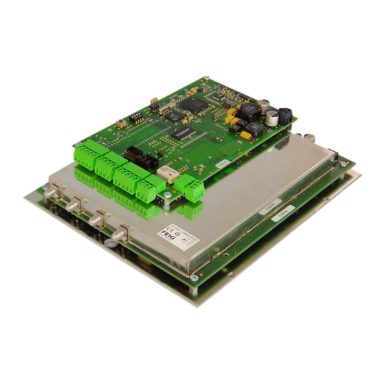
® OBID i-scan Montage ID ISC.LRMU2000 2.3 Montage Zur Befestigung des Readers befinden sich auf der Montageplatte (schraffiert) vier Durchbrüche. Bild 2-1: Reader mit Montageplatte FEIG ELECTRONIC GmbH Seite 8 von 56 M60802-2de-ID-B.doc... -
Page 9: Anschlussklemmen
® OBID i-scan Montage ID ISC.LRMU2000 2.4 Anschlussklemmen Bild 2-2: Anschlussklemmen des Readers FEIG ELECTRONIC GmbH Seite 9 von 56 M60802-2de-ID-B.doc... -
Page 10: Antennenanschluss
X13 / Pin 1 Vcc - Versorgungsspannung X13 / Pin 2 Ground – Versorgungsspannung Table 2-4: Pinbelegung Versorgungsspannung Bild 2-3: Anschluss der Versorgungsspannung Hinweis: • Eine Verpolung der Versorgungsspannung kann zur Zerstörung des Gerätes führen. FEIG ELECTRONIC GmbH Seite 10 von 56 M60802-2de-ID-B.doc... -
Page 11: Eingänge / Ausgänge
Klemme Kurzzeichen Beschreibung Kollektor – Ausgang 1 Emitter – Ausgang 1 + Eingang 1 - Eingang 1 Table 2-5: Pinbelegung Optokoppler ext. ext. Bild 2-4: Interne und mögliche externe Beschaltung der Optokoppler FEIG ELECTRONIC GmbH Seite 11 von 56 M60802-2de-ID-B.doc... - Page 12 Hinweise: • Der Eingang ist für eine maximale Eingangsspannung von 24 V DC und einem Ein- gangsstrom von maximal 20 mA ausgelegt. • Verpolung oder Überlastung des Eingangs führt zu dessen Zerstörung. FEIG ELECTRONIC GmbH Seite 12 von 56 M60802-2de-ID-B.doc...
-
Page 13: Relais
• Der Relaisausgang ist nur zum Schalten ohmscher Lasten vorgesehen. Im Falle einer induktiven Last sind die Relaiskontakte durch eine externe Schutzbeschaltung zu schüt- zen. ext. Bild 2-5: Interne und mögliche externe Beschaltung des Relaisausgangs FEIG ELECTRONIC GmbH Seite 13 von 56 M60802-2de-ID-B.doc... -
Page 14: Readersynchronisation (Not Used)
Mit der Readersynchronisation können verschiedene Aktionen der Reader synchronisiert werden. Klemme Kurzzeichen Beschreibung - Eingang + Eingang - Ausgang +Ausgang Table 2-8: Pinbelegung Readersynchronisation OUT+ (Z+) OUT- (Y-) (B+) (A-) Bild 2-6: Eingang und Ausgang der Synchronisation FEIG ELECTRONIC GmbH Seite 14 von 56 M60802-2de-ID-B.doc... -
Page 15: Anschluss Externer Diagnose-Leds
Bild 2-7 Anschluss externer LEDs an X14 Hinweis: • Die Ausgänge an X14 sind nur zum Schalten einer externen LED vorgesehen. Überlas- tung der Ausgänge durch andere Lasten kann zu deren Zerstörung führen. FEIG ELECTRONIC GmbH Seite 15 von 56 M60802-2de-ID-B.doc... -
Page 16: Schnittstellen
Table 2-10: Pinbelegung RS232-Schnittstelle 9-pol. D-SUB-Buchse <−> X8 / 1 Pin 5 <−> X8 / 2 Pin 3 <−> X8 / 3 Pin 2 Bild 2-8: Verdrahtungsbeispiel für den Anschluss der RS232-Schnittstelle FEIG ELECTRONIC GmbH Seite 16 von 56 M60802-2de-ID-B.doc... -
Page 17: Rs485/Rs422 Schnittstelle
RS485/RS422 – (A -) RS485/RS422 – (B +) RS422 – (Y -) RS422 – (Z +) Table 2-11: Pinbelegung RS485/RS422-Schnittstelle RS422 (Z+) RS422 (Y-) RS485/RS422 (B+) RS485/RS422 (A-) RS485/RS422 Bild 2-9: Anschlussbelegung der RS485/RS422-Schnittstelle FEIG ELECTRONIC GmbH Seite 17 von 56 M60802-2de-ID-B.doc... -
Page 18: Bedien- Und Anzeigeelemente
Leuchtet während der Reader-Initialisierung nach dem Ein- schalten bzw. nach einem Reset. Leuchtet bei einem Fehler im RF-Teil des Readers. Der Feh- lertyp kann per Software über die RS232/RS485-Schnittstelle ausgelesen werden Tabelle 3-1: Konfiguration der LED FEIG ELECTRONIC GmbH Seite 18 von 56 M60802-2de-ID-B.doc... -
Page 19: Taster / Schalter
1. DIP4 auf On, anschließend Reset Taster T1 drücken 2. DIP4 auf Off, anschließend Reset Taster T1 drücken Die grüne und blaue LED blinken abwechselnd. 3. Reset Taster T1 nochmals betätigen. Bild 3-1 FEIG ELECTRONIC GmbH Seite 19 von 56 M60802-2de-ID-B.doc... -
Page 20: Inbetriebnahme
Pull-Down an RS422 - Y ohne Pull-Down an RS422 – Y Abschlusswiderstand ohne Abschlusswiderstand RS422 - Y ⇔ RS422 - Z RS422 - Y ⇔ RS422 - Z Table 4-2: Abschlusswiderstände der RS485/RS422 FEIG ELECTRONIC GmbH Seite 20 von 56 M60802-2de-ID-B.doc... - Page 21 Tabelle 4-3 zeigt die Standardkonfiguration der Jumper J9 bis J12. Diese sind für die RS485 und RS422 identisch. LRMU2000 LRMU2000 Jumper Gerätevarianten mit ACC Gerätevarianten ohne ACC Geschlossen offen Geschlossen Geschlossen offen offen offen Geschlossen Table 4-3: Standardkonfiguration der RS485/RS422 FEIG ELECTRONIC GmbH Seite 21 von 56 M60802-2de-ID-B.doc...
- Page 22 Die Adressvergabe erfolgt über den Host-Rechner. Mit Hilfe der Software können dem Reader die Adressen "0" bis "254" zugewiesen werden. Hinweis: Da alle Reader werksseitig die Adresse 0 eingestellt haben, müssen sie nacheinander ange- schlossen und konfiguriert werden. FEIG ELECTRONIC GmbH Seite 22 von 56 M60802-2de-ID-B.doc...
-
Page 23: Reader Leistungseinstellung
Bei einer linearen Antenne ist der maximale lineare Gewinn [dBi] anzusetzen. - Antennengewinn + Kabeldämpfung + 2,1dB Für die Berechnung der am Reader einzustellenden Sendeleistung steht eine „Calc-RF-Power.xls“ Excel Datei zur Verfügung. Verfügbar von Feig Electronic GmbH. Beispiel: ** lineare Antenne = „0“, zirkulare Antennen = „1“... - Page 24 In dem Fall kann auch die Excel-Datei „Calc-RF-Power.xls“ verwendet werden. Beispiel: ** lineare Antenne = „0“, zirkulare Antennen = „1“ Beispiel: Beträgt der Antennengewinn einer linearen Antenne 8dBi, so muss die Readerausgangsleistung um 2dB reduziert werden (Reader: 28dBm / 0,63Watt). FEIG ELECTRONIC GmbH Seite 24 von 56 M60802-2de-ID-B.doc...
- Page 25 ® OBID i-scan Montage ID ISC.LRMU2000 Funkzulassungen 5.1 Europa (CE) FEIG ELECTRONIC GmbH Seite 25 von 56 M60802-2de-ID-B.doc...
- Page 26 Commission Rules permitting the operation of this device. Warning: Changes or modification made to this equipment not expressly approved by FEIG ELECTRONIC GmbH may void the FCC authorization to operate this equipment. FEIG ELECTRONIC GmbH Seite 26 von 56...
- Page 27 - 1 Relais ( 1 x Wechsler) • Eingänge - 1 Optokoppler max. 24 V DC/ 20 mA • Schnittstellen - RS232 - RS485 / RS422 (wahlweise einstellbar) • Protokoll Modi - FEIG ISO Host FEIG ELECTRONIC GmbH Seite 27 von 56 M60802-2de-ID-B.doc...
- Page 28 Zulassung Funk - Europa EN 302 208 - USA EN 300 220 FCC 47 CFR Part 15 • EN 301 489 • Sicherheit - Niederspannung EN 60950 - Human Exposure EN 50364 FEIG ELECTRONIC GmbH Seite 28 von 56 M60802-2de-ID-B.doc...
- Page 30 FEIG ELECTRONIC call explicit attention that devices which are subject of this document are not designed with components and testing methods for a level of reliability suitable for use in or in connection with surgical implants or as critical components in any life support systems whose failure to perform can reasonably be expected to cause significant injury to a human.
- Page 31 2.9.1 RS232 interface......................44 2.9.2 RS485/RS422 interface....................45 Operating and Display Elements LEDs ..........................46 Buttons / Switches ......................47 Hardware Configuration-Reset...................47 Startup Interface configuration....................48 4.1.1 RS485/RS422 .......................48 Reader Power adjustment ..................51 4.2.1 EU-Reader (EN302 208) ....................51 FEIG ELECTRONIC GmbH Page 31 of 56 M60802-2de-ID-B.doc...
- Page 32 ® OBID i-scan Installation ID ISC.LRMU2000 4.2.2 FCC-Reader ........................52 Radio Approvals Europe (CE)........................53 USA (FCC) ........................54 Technical Data FEIG ELECTRONIC GmbH Page 32 of 56 M60802-2de-ID-B.doc...
- Page 33 Although this device doesn't exceed the valid limits for electromagnetic fields you should keep a minimum distance of 25 cm between the device and your cardiac pacemaker and not stay in the immediate proximity of the device’s antenna for any length of time. FEIG ELECTRONIC GmbH Page 33 of 56 M60802-2de-ID-B.doc...
-
Page 34: Performance Features Of Reader Family Id Isc.lru2000
Device version with ACC and internal antenna for USA Table 2-1 Reader types Reader module type Description ID ISC.LRMU2000-B-EU Module version without ACC for Europe ID ISC.LRMU2000-B-FCC Module version without ACC for USA Table 2-2 Reader module types FEIG ELECTRONIC GmbH Page 34 of 56 M60802-2de-ID-B.doc... -
Page 35: Installation
® OBID i-scan Installation ID ISC.LRMU2000 2.3 Installation To mount the reader there are four drilled holes in the mounting plate (hatched). Fig. 2-1: Reader witch mounting plate FEIG ELECTRONIC GmbH Page 35 of 56 M60802-2de-ID-B.doc... -
Page 36: Terminals
® OBID i-scan Installation ID ISC.LRMU2000 2.4 Terminals Fig. 2-2: Reader terminals FEIG ELECTRONIC GmbH Page 36 of 56 M60802-2de-ID-B.doc... -
Page 37: Antenna Connection
The maximum tightening torque for the SMA sockets is 0.45 Nm (4.0 lbf in). Caution: Exceeding the tightening torque will destroy the plug. Terminal Description X1, X2 Connection for external antennas X3, X4 (input impedance 50Ω) Table 2-3: External antenna connection FEIG ELECTRONIC GmbH Page 37 of 56 M60802-2de-ID-B.doc... -
Page 38: Supply Voltage
Vcc – supply voltage X13 / Pin 2 Ground – supply voltage Table 2-4: Pin-outs for supply voltage Fig. 2-3 Connecting the supply voltage Note: • Reversing the supply voltage polarity may destroy the device. FEIG ELECTRONIC GmbH Page 38 of 56 M60802-2de-ID-B.doc... -
Page 39: Inputs / Outputs
Abbreviation Description Collector – Output 1 Emitter – Output 1 + Input 1 - Input 1 Table 2-5: Optocoupler pin-outs ext. ext. Fig. 2-4: Internal and possible external wiring of the optocouplers FEIG ELECTRONIC GmbH Page 39 of 56 M60802-2de-ID-B.doc... - Page 40 The input is configured for a maximum input voltage of 24 V DC and an input current of max. 20 mA. • Polarity reversal or overload on the input will destroy it. FEIG ELECTRONIC GmbH Page 40 of 56 M60802-2de-ID-B.doc...
-
Page 41: Relay
• The relay output is intended for switching resistive loads only. If an inductive load is connected, the relay contacts must be protected by means of an external protection circuit. ext. Fig. 2-5: Internal and possible external wiring of the relay output FEIG ELECTRONIC GmbH Page 41 of 56 M60802-2de-ID-B.doc... -
Page 42: Reader Synchronization (Not Used)
Reader synchronization can be used to synchronize various Reader actions. Terminal Abbreviation Description - Input + Input - Output + Output Table 2-8: Reader synchronization pin-outs OUT+ (Z+) OUT- (Y-) (B+) (A-) Fig. 2-6: Synchronization input and output FEIG ELECTRONIC GmbH Page 42 of 56 M60802-2de-ID-B.doc... -
Page 43: External Diagnostic Led Connections
Externe LEDs Fig. 2-7: Connecting external LEDs to X14 Note: • The outputs on X14 are intended for switching an external LED only. Overloading the outputs with other loads may destroy them. FEIG ELECTRONIC GmbH Page 43 of 56 M60802-2de-ID-B.doc... -
Page 44: Interfaces
Table 2-10: RS232 interface pin-outs 9-pol. D-SUB-Jack <−> X8 / 1 Pin 5 <−> X8 / 2 Pin 3 <−> X8 / 3 Pin 2 Fig. 2-8: Wiring example for connecting the RS232 interface FEIG ELECTRONIC GmbH Page 44 of 56 M60802-2de-ID-B.doc... -
Page 45: Rs485/Rs422 Interface
RS485/RS422 – (B +) RS422 – (Y -) RS422 – (Z +) Table 2-11: RS485/RS422 interface pin-outs RS422 (Z+) RS422 (Y-) RS485/RS422 (B+) RS485/RS422 (A-) RS485/RS422 Fig. 2-9: Wiring example for the RS485/RS422 interface FEIG ELECTRONIC GmbH Page 45 of 56 M60802-2de-ID-B.doc... -
Page 46: Operating And Display Elements
Comes on when there is an error in the RF section of the Reader. The error type can be read out via software over the RS232/RS485 interface Table 3-1: LED configuration FEIG ELECTRONIC GmbH Page 46 of 56 M60802-2de-ID-B.doc... -
Page 47: Buttons / Switches
1. DIP4 to ON position, than press Reset button T1. 2. DIP4 to OFF position, than press Reset button T1 again. The green and the blue LED flashes alternating 3. Press the Reset button T1 a second time. Fig. 3-1 FEIG ELECTRONIC GmbH Page 47 of 56 M60802-2de-ID-B.doc... -
Page 48: Startup
Pull-Down on RS422 - Y without Pull-Down on RS422 – Termination resistor without Termination resistor RS422 - Y ⇔ RS422 - Z RS422 - Y ⇔ RS422 - Z Table 4-2: Termination resistors for RS485/RS422 FEIG ELECTRONIC GmbH Page 48 of 56 M60802-2de-ID-B.doc... - Page 49 J9 through J12. These are identical for RS485 and RS422. LRMU2000 Jumper device version without ACC open closed open closed Table 4-3: Standard configuration for RS485/RS422 FEIG ELECTRONIC GmbH Page 49 of 56 M60802-2de-ID-B.doc...
- Page 50 The address is assigned by the host computer. The software is used to assign addresses “0” through “254” to the Reader. Note: Since all Readers are factory set with address „0“, they must be connected and configured one after the other. FEIG ELECTRONIC GmbH Page 50 of 56 M60802-2de-ID-B.doc...
-
Page 51: Reader Power Adjustment
- Antenna gain + Cable loss + 2,1dB For the calculation of the reader output power P an Excel file „Calc-RF-Power.xls“ can be used. Available from Feig Electronic GmbH. Example: ** linear antenna = „0“, circular antenna = „1“ In Table 4-4 the allowed antenna power is shown depending on the frequency (channel). - Page 52 ** linear antenna = „0“, circular antenna = „1“ Example: If the antenna gain of a linear antenna is 8dBi, the reader output power must be reduced by 2 dB (Reader: 28dBm / 063Watt). FEIG ELECTRONIC GmbH Page 52 of 56 M60802-2de-ID-B.doc...
- Page 53 ® OBID i-scan Installation ID ISC.LRMU2000 Radio Approvals 5.1 Europe (CE) FEIG ELECTRONIC GmbH Page 53 of 56 M60802-2de-ID-B.doc...
- Page 54 Commission Rules permitting the operation of this device. Warning: Changes or modification made to this equipment not expressly approved by FEIG ELECTRONIC GmbH may void the FCC authorization to operate this equipment. FEIG ELECTRONIC GmbH Page 54 of 56...
- Page 55 24 V DC / 2 A - 1 relay ( 1 x changeover) • Inputs - 1 optocoupler max. 24 V DC/ 20 mA • Interfaces - RS232 - RS485 / RS422 (selectable) FEIG ELECTRONIC GmbH Page 55 of 56 M60802-2de-ID-B.doc...
- Page 56 RF approval - Europe EN 302 208 EN 300 220 - USA FCC 47 CFR Part 15 • EN 301 489 • Safety - Low-Voltage EN 60950 - Human Exposure EN 50364 FEIG ELECTRONIC GmbH Page 56 of 56 M60802-2de-ID-B.doc...
Need help?
Do you have a question about the OBID i-scan ID ISC.LRMU2000 Series and is the answer not in the manual?
Questions and answers