
Related Manuals for Feig Electronic OBID i-scan ID ISC.MR101-USB


Summary of Contents for Feig Electronic OBID i-scan ID ISC.MR101-USB
- Page 1 ® INSTALLATION OBID i-scan ID ISC.MR101-USB ID ISC.PR101-USB final public (B) 2007-09-25 M50805-4e-ID-B.doc...
- Page 2 GmbH does not give any guarantee promise for perfect function in cross environments. FEIG ELECTRONIC GmbH assumes no responsibility for the use of any information contained in this document and makes no representation that they free of patent infringement. FEIG ELECTRONIC GmbH does not convey any license under its patent rights nor the rights of others.
-
Page 3: Table Of Contents
3.6.2. ID ISC.PR101 ......................11 4. Control and display elements 4.1. LED .............................12 5. Technical Data 6. Approvals 6.1. Europe (CE)........................15 6.2. Canada (IC) ........................16 6.3. USA.............................17 6.3.1. FCC ..........................17 6.3.2. UL ..........................17 7. Appendix FEIG ELECTRONIC GmbH Page 3 of 20 M50805-4e-ID-B.doc... - Page 4 ® OBID i-scan Installation ID ISC.MR101-USB / ID ISC.PR101-USB 7.1. Accessories ........................18 7.1.1. Wall mounting kit ID ISC.MS.MR/PR-A ...............19 7.1.2. Antennas........................20 FEIG ELECTRONIC GmbH Page 4 of 20 M50805-4e-ID-B.doc...
- Page 5 Although this device doesn't exceed the valid limits for electromagnetic fields you should keep a minimum distance of 25 cm between the device and your cardiac pacemaker and not stay in an immediate proximity of the device respective the antenna for some time. FEIG ELECTRONIC GmbH Page 5 of 20 M50805-4e-ID-B.doc...
-
Page 6: Performance Features Of The Readers
ID ISC.MR101-USB USB-Interface and external antenna ID ISC.PR101-A asynchronous RS232 interface and internal antenna ID ISC.PR101-A-M asynchronous RS232 interface and internal antenna - Module ID ISC.PR101-USB USB-Interface and internal antenna Table 1: Reader-Types FEIG ELECTRONIC GmbH Page 6 of 20 M50805-4e-ID-B.doc... -
Page 7: Assembly And Wiring
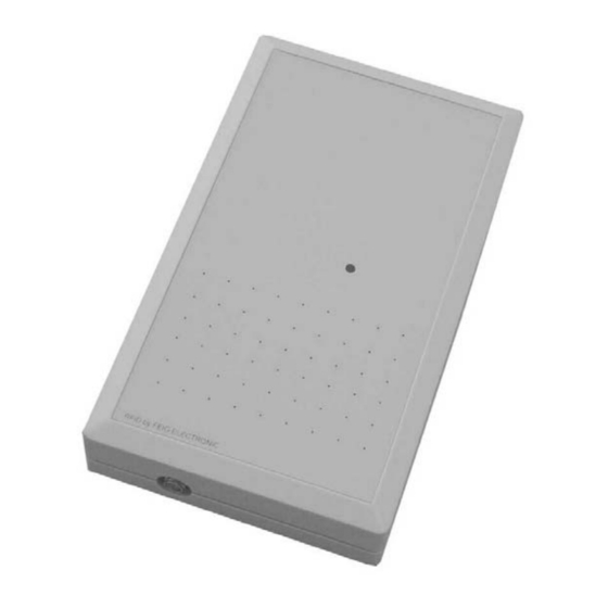
(reinforcements) or metallized surfaces, as these surfaces reduce the detection range of the reader. The distance between the reader and such surfaces should be min. 10 cm. 3.1. Dimensions Fig. 1: Enclosure (all dimensions in mm) FEIG ELECTRONIC GmbH Page 7 of 20 M50805-4e-ID-B.doc... -
Page 8: Connector Sockets
The reader ID ISC.PR101-USB does not need an external power supply. The power supply takes place via the USB-Interface (Bus-powered). The USB-Interface must support a current of about 500mA (High Powered Interface). FEIG ELECTRONIC GmbH Page 8 of 20 M50805-4e-ID-B.doc... -
Page 9: Power Supply (Only Id Isc.mr101)
Input voltage 95 - 265V AC Table 4: Recommended power supply Note: The power supply is supplied with a DC/ plug 2.5mm x 5.5mm. This is compatible with the readers socket X1. FEIG ELECTRONIC GmbH Page 9 of 20 M50805-4e-ID-B.doc... -
Page 10: Antenna Terminal X4 (Only Id Isc.mr101)
Q the antenna must be supplied with a 50 Ohm source such as a network analyzer or frequency generator. • When connecting an antenna, ensure that it does not exceed the permissible limits pre- scribed by the national regulations for radio frequency devices. FEIG ELECTRONIC GmbH Page 10 of 20 M50805-4e-ID-B.doc... -
Page 11: Starting
100mA. The USB-Interface must be a High Powered Interface. A High Powered Interface supports the reader up to 500mA. Note: The function of the reader is only guaranteed if it is connected to a High Powered Interface. FEIG ELECTRONIC GmbH Page 11 of 20 M50805-4e-ID-B.doc... -
Page 12: Control And Display Elements
Turns on when the Reader is ready „LABEL“ LED red Turns on when a transponder is detected. „INITIALIZING“ LED orange Flashes during Reader initialization after power-up. Table 6: Standard configuration of the LEDs FEIG ELECTRONIC GmbH Page 12 of 20 M50805-4e-ID-B.doc... -
Page 13: Technical Data
Operating frequency 13,56 MHz • Transmitting power ID ISC.MR101: 1,0 W ± 2dB ID ISC.PR101: 0,5 W ± 2dB • Antenna connection SMA female (50Ω) (only ID ISC.MR101) • Interfaces USB (12 Mbit) FEIG ELECTRONIC GmbH Page 13 of 20 M50805-4e-ID-B.doc... - Page 14 EN 300 330 - USA FCC 47 CFR Part 15 - Canada RSS-Gen Issue 1, RSS-210 Issue 6 • EN 300 489 • Safety - Low-Voltage UL 60950-1 - Human Exposure EN 50364 FEIG ELECTRONIC GmbH Page 14 of 20 M50805-4e-ID-B.doc...
-
Page 15: Approvals
® OBID i-scan Installation ID ISC.MR101-USB / ID ISC.PR101-USB 6. Approvals 6.1. Europe (CE) FEIG ELECTRONIC GmbH Page 15 of 20 M50805-4e-ID-B.doc... -
Page 16: Canada (Ic)
The required antenna impedance is 50 ohms. An SMA so- cket is provided on the circuit board for connecting the external antenna. Article No. Part No. 1663.000.00 ID ISC.ANT340/240-A 2396.000.00 ID ISC.ANT340/240-B Table 7: Antennas with IC Approval FEIG ELECTRONIC GmbH Page 16 of 20 M50805-4e-ID-B.doc... -
Page 17: Usa
An SMA socket is provided on the circuit board for connecting the external antenna. Article No. Part No. 1663.000.00 ID ISC.ANT340/240-A 2396.000.00 ID ISC.ANT340/240-B Table 8: Antennas with FCC Approval 6.3.2. UL FEIG ELECTRONIC GmbH Page 17 of 20 M50805-4e-ID-B.doc... - Page 18 Dimensions: 340mm x 240mm x 9mm Degree of Protection: IP30 2396.000.00 ID ISC.ANT340/240-B Externe Antenne ohne Gehäuse 1451.000.00 ID ISC.ANT300/300 External antenna Dimensions: 300mm x 300mm x 30mm Degree of Protection: IP65 Table 9: Accessories FEIG ELECTRONIC GmbH Page 18 of 20 M50805-4e-ID-B.doc...
- Page 19 • Attach the individual wall hangers using the screws supplied with the mounting kit. Fig. 4 + 5: Mounting wall hangers Fig. 6 + 7: Mounting drill dimensioning (all dimensions in mm) FEIG ELECTRONIC GmbH Page 19 of 20 M50805-4e-ID-B.doc...
- Page 20 ® OBID i-scan Installation ID ISC.MR101-USB / ID ISC.PR101-USB 7.1.2. Antennas Fig. 8: ID ISC.ANT340/240 Fig. 9: ID ISC.ANT300/300 FEIG ELECTRONIC GmbH Page 20 of 20 M50805-4e-ID-B.doc...
Need help?
Do you have a question about the OBID i-scan ID ISC.MR101-USB and is the answer not in the manual?
Questions and answers